


All Exams >
Electrical Engineering (EE) >
6 Months Preparation for GATE Electrical >
All Questions
All questions of Bridges and Potentiometers for Electrical Engineering (EE) Exam
State True / False for following statements:
1. Owen’s bridge is used for inductance measurement of low Q coils.
2. De-Sauty’s bridge is used for measurement of perfect capacitors.- a)True, False
- b)False, False
- c)False, True
- d)True, True
Correct answer is option 'D'. Can you explain this answer?
State True / False for following statements:
1. Owen’s bridge is used for inductance measurement of low Q coils.
2. De-Sauty’s bridge is used for measurement of perfect capacitors.
1. Owen’s bridge is used for inductance measurement of low Q coils.
2. De-Sauty’s bridge is used for measurement of perfect capacitors.
a)
True, False
b)
False, False
c)
False, True
d)
True, True

|
Pioneer Academy answered |
Owen’s bridge is used for the inductance measurement of low Q coils.
De-Sauty’s bridge is used for the measurement of perfect capacitors.
So that both statements are true.
De-Sauty’s bridge is used for the measurement of perfect capacitors.
So that both statements are true.

The Schering bridge. one of the most important AC bridge
(A) It is used for capacitance measurement
(B) It is used for phase angle measurement
(C) It is used for inductance measurement
(D) It is used for resistance measurement
(E) It is used for torque measurement
Choose the correct answer from the options given below:- a)(A) and (B) only
- b)(C) only
- c)(D) only
- d)(E) only
Correct answer is option 'A'. Can you explain this answer?
The Schering bridge. one of the most important AC bridge
(A) It is used for capacitance measurement
(B) It is used for phase angle measurement
(C) It is used for inductance measurement
(D) It is used for resistance measurement
(E) It is used for torque measurement
Choose the correct answer from the options given below:
(A) It is used for capacitance measurement
(B) It is used for phase angle measurement
(C) It is used for inductance measurement
(D) It is used for resistance measurement
(E) It is used for torque measurement
Choose the correct answer from the options given below:
a)
(A) and (B) only
b)
(C) only
c)
(D) only
d)
(E) only

|
Cstoppers Instructors answered |
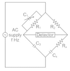
Schering Bridge:
Schering bridge is a type of AC bridge that is used to measure the dissipation factor (dielectric loss) or phase angle and capacitance.
The circuit of the Schering bridge is shown below:
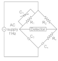
When the bridge is in the balanced condition, zero current passes through the detector, which shows that the potential across the detector is zero.
At balance condition:
If the flux linkage in coil 1 is 3Wb and it has 500 turns and the current in coil 2 is 2A, calculate the mutual inductance.- a)750H
- b)500H
- c)450H
- d)900H
Correct answer is option 'A'. Can you explain this answer?
If the flux linkage in coil 1 is 3Wb and it has 500 turns and the current in coil 2 is 2A, calculate the mutual inductance.
a)
750H
b)
500H
c)
450H
d)
900H
|
|
Pioneer Academy answered |
We know that mutual inductance is the product of the number of turns in one coil and the flux linkages of that coil, divided by the current in the other coil.
M = 3*500/2 = 750H.
M = 3*500/2 = 750H.
The flux linkage in coil 1 is x and it has 500 turns and the current in coil 2 is 2A, calculate the value of x if the mutual inductance is 750H.- a)1Wb
- b)2Wb
- c)3Wb
- d)4Wb
Correct answer is option 'C'. Can you explain this answer?
The flux linkage in coil 1 is x and it has 500 turns and the current in coil 2 is 2A, calculate the value of x if the mutual inductance is 750H.
a)
1Wb
b)
2Wb
c)
3Wb
d)
4Wb
|
|
Cstoppers Instructors answered |
We know that mutual inductance is the product of the number of turns in one coil and the flux linkages of that coil, divided by the current in the other coil.
φ = 750*2/500 = 3Wb.
φ = 750*2/500 = 3Wb.
Which of the following is used to eliminate the effect of earth capacitances?- a)Schering bridge
- b)Wein's bridge
- c)Wagner's earthing device
- d)Electrostatic voltmeter
Correct answer is option 'C'. Can you explain this answer?
Which of the following is used to eliminate the effect of earth capacitances?
a)
Schering bridge
b)
Wein's bridge
c)
Wagner's earthing device
d)
Electrostatic voltmeter

|
Gate Gurus answered |
Wagner's Earthing Device:
- The Wagner earthing device is used for removing the effect of earth capacitances.
- At high frequency, stray capacitance is induced between the bridge elements, ground, and between the arms of the bridge.
- This stray element causes an error in the measurement.
- It is a type of voltage divider circuit used to reduce the error which occurs because of stray capacitance.
- The Wagner Earth device provides high accuracy to the bridge.
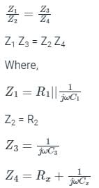
Circuit diagram for Wagner’s earthing device:
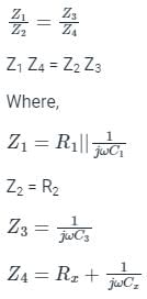
Where,
Z1 Z2 Z3 Z4 is the impedance arm of the bridge.
Z5 and Z6 are the two variable impedances of the Wagner Earth Device
C1, C2 C3, and C4 are the stray capacitances of the bridge
D is the detector
a, b, c, d, and GND1 are nodes of the bridge
In Wagner’s earthing device is adjusted such that b, d, and GND1 have equal potential
At the balanced condition,
The capacitance C1, C2, C3, C4 all are eliminated from the bridge circuit along with the impedances Z5 and Z6.
In a Schering bridge, the dial of the variable capacitor is calibrated directly in terms of the dissipation factor of the unknown arm. At 50 Hz frequency, the value of the dissipation factor of the unknown capacitor was found to be D. What would be the value of the dissipation factor at 60 Hz- a)6 D
- b)1 / 6 D
- c)5 / 6 D
- d)6 / 5 D
Correct answer is option 'D'. Can you explain this answer?
In a Schering bridge, the dial of the variable capacitor is calibrated directly in terms of the dissipation factor of the unknown arm. At 50 Hz frequency, the value of the dissipation factor of the unknown capacitor was found to be D. What would be the value of the dissipation factor at 60 Hz
a)
6 D
b)
1 / 6 D
c)
5 / 6 D
d)
6 / 5 D
|
|
Pooja Patel answered |
Concept:
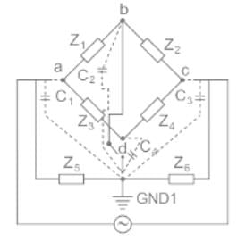
Schering bridge:
At bridge balance condition,
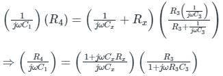
At bridge balance condition,
⇒ R4Cx (1 + jωR3C3) = R3C1 (1 + jω Cx Rx)
By comparing both sides
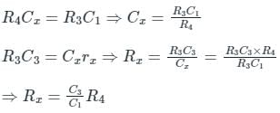
Dissipation factor = ωCxRx = ωR3C3 = 2πf R3C3
Dissipation factor = ωCxRx = ωR3C3 = 2πf R3C3
Dissipation factor α frequency(f) --------(1)
Calculation:
Given:
Dissipation factor D at frequency 50Hz
Let Dissipation factor x at frequency 60Hz
From equation 1:
f1/f2 = D/z
x = 6/5 D
f1/f2 = D/z
x = 6/5 D
Which of the following statements is not true with respect to Maxwell's bridge?- a)It cannot be used for the measurement of high Q values.
- b)It is not suitable for measurement of Q values less than 1.
- c)The equilibrium equation is dependent on the frequency of measurement.
- d)The scale directly tells the inductance.
Correct answer is option 'C'. Can you explain this answer?
Which of the following statements is not true with respect to Maxwell's bridge?
a)
It cannot be used for the measurement of high Q values.
b)
It is not suitable for measurement of Q values less than 1.
c)
The equilibrium equation is dependent on the frequency of measurement.
d)
The scale directly tells the inductance.
|
|
Juhi Joshi answered |
Equilibrium Equation in Maxwell's Bridge
Maxwell's bridge is a type of bridge circuit used for the measurement of inductance. The equilibrium equation in Maxwell's bridge is given by:
\[ R_1R_3 = R_2R_4 + L^2 \]
This equation is not dependent on the frequency of measurement. The equilibrium equation is based on the balance of the bridge circuit components at a specific frequency, which is usually the frequency at which the bridge is balanced for accurate measurements.
Why the Statement is Not True
The statement that the equilibrium equation in Maxwell's bridge is dependent on the frequency of measurement is not true. The equilibrium equation is determined by the values of the resistors and the inductor in the bridge circuit, and it is not influenced by the frequency at which the measurement is taken. The frequency of measurement may affect the sensitivity of the bridge circuit to changes in inductance, but it does not directly impact the equilibrium equation itself.
In summary, the equilibrium equation in Maxwell's bridge is independent of the frequency of measurement, and it is the balance of the components in the bridge circuit that determines the inductance value.
Which of the following bridges is used for most accurate inductance measurement of inductors having high value of Q-factor?- a)Hay bridge
- b)Schering bridge
- c)Kelvin bridge
- d)Maxwell bridge
Correct answer is option 'A'. Can you explain this answer?
Which of the following bridges is used for most accurate inductance measurement of inductors having high value of Q-factor?
a)
Hay bridge
b)
Schering bridge
c)
Kelvin bridge
d)
Maxwell bridge
|
|
Pooja Patel answered |
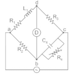
Hay’s bridge:
- In Hay’s bridge, a resistance is connected in series with a standard capacitor.
- Hay’s bridge is used for the measurement of the inductance of coils with high-quality factors.
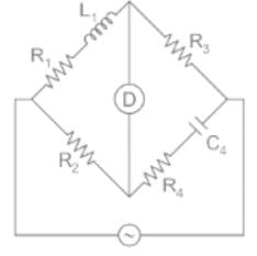
Maxwell’s inductance-capacitance bridge:
In Maxwell’s inductance bridge resistance is connected in parallel with the standard capacitor.
Which type of the bridge circuit among the following is used for measurement of capacitance?- a)Anderson Bridge
- b)Schering Bridge
- c)Heaviside Campbell Bridge
- d)None of these above
Correct answer is option 'B'. Can you explain this answer?
Which type of the bridge circuit among the following is used for measurement of capacitance?
a)
Anderson Bridge
b)
Schering Bridge
c)
Heaviside Campbell Bridge
d)
None of these above
|
|
Pooja Patel answered |
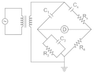
Schering Bridge:
Schering bridge is a type of AC bridge that is used to measure the dissipation factor (dielectric loss) or phase angle and capacitance.
The circuit of the Schering bridge is shown below:
When the bridge is in the balanced condition, zero current passes through the detector, which shows that the potential across the detector is zero.
At balance condition:
 =
=
= Telephone companies make use of the Wheatstone bridge for _________.- a)measuring the telephone resistance
- b)computing the line strength
- c)maintaining Dialtone
- d)locating the cable faults
Correct answer is option 'D'. Can you explain this answer?
Telephone companies make use of the Wheatstone bridge for _________.
a)
measuring the telephone resistance
b)
computing the line strength
c)
maintaining Dialtone
d)
locating the cable faults
|
|
Sinjini Reddy answered |
Explanation:
Wheatstone Bridge:
- The Wheatstone bridge is a circuit used to measure an unknown electrical resistance by balancing two legs of a bridge circuit.
- It consists of four resistors, a voltage source, and a galvanometer.
Locating Cable Faults:
- Telephone companies use the Wheatstone bridge to locate faults in cables.
- When a fault occurs in a cable, it creates an imbalance in the resistance values in the circuit.
- By using the Wheatstone bridge, technicians can determine the exact location of the fault by measuring the resistance values on either side of the fault.
Working Principle:
- The Wheatstone bridge works on the principle of null detection, where the galvanometer reads zero when the bridge is balanced.
- If there is a fault in the cable, the resistance values change, causing the galvanometer to deflect from zero.
- By adjusting the known resistances in the bridge circuit, technicians can bring the bridge back into balance, indicating the location of the fault.
Benefits:
- Using the Wheatstone bridge for locating cable faults is a precise and efficient method.
- It helps in quickly identifying the exact location of the fault without the need for extensive manual testing.
- This method saves time and resources for telephone companies in maintaining and repairing their communication networks.
By using the variations on a Wheatstone bridge we can _________.- a)measure quantities such as voltage, current, and power
- b)measure high resistance values
- c)measure quantities such as complex power
- d)measure quantities such as capacitance, inductance, and impedance
Correct answer is option 'D'. Can you explain this answer?
By using the variations on a Wheatstone bridge we can _________.
a)
measure quantities such as voltage, current, and power
b)
measure high resistance values
c)
measure quantities such as complex power
d)
measure quantities such as capacitance, inductance, and impedance
|
|
Sarita Yadav answered |
In its simplest form, a Whetstone bridge consists of resistive arms. A Wheatstone bridge is used to measure quantities such as capacitance, inductance, and impedance by using the variations.
A bridge circuit works at a frequency of 3 kHz. Which detector can be used for detecting the null conditions in the bridge?- a)Vibration galvanometer and tunable amplifiers.
- b)Vibration galvanometer and head phones.
- c)Headphones and tunable amplifiers.
- d)Vibration galvanometer, headphones and tunable amplifiers.
Correct answer is option 'C'. Can you explain this answer?
A bridge circuit works at a frequency of 3 kHz. Which detector can be used for detecting the null conditions in the bridge?
a)
Vibration galvanometer and tunable amplifiers.
b)
Vibration galvanometer and head phones.
c)
Headphones and tunable amplifiers.
d)
Vibration galvanometer, headphones and tunable amplifiers.
|
|
Nikhil Iyer answered |
For 3 kHz frequency headphone (Range - 250 Hz to 4 kHz) and tuned amplifier detector (Range - 10 Hz to 100 kHz) will be used.
In measurement of resistance by “Carey Foster bridge” no error is introduced due to- a)connecting leads
- b)thermoelectric emfs
- c)contact resistance
- d)ail of the above
Correct answer is option 'D'. Can you explain this answer?
In measurement of resistance by “Carey Foster bridge” no error is introduced due to
a)
connecting leads
b)
thermoelectric emfs
c)
contact resistance
d)
ail of the above
|
|
Raj Choudhary answered |
“Carey Foster slide wire bridge” is a special type of bridge circuit which is used for the measurement of medium resistance by comparing with a standard known resistance. This bridge circuit will give no error due to connecting lead resistances, thermoelectric emfs and contact resistances.
In which type of frequency meter, the frequency is found when the torque’ in the moving coil becomes zero?- a)Vibrating reed type
- b)Permanent Magnet moving Coil type
- c)Moving iron type
- d)Electrical resonance type
Correct answer is option 'D'. Can you explain this answer?
In which type of frequency meter, the frequency is found when the torque’ in the moving coil becomes zero?
a)
Vibrating reed type
b)
Permanent Magnet moving Coil type
c)
Moving iron type
d)
Electrical resonance type
|
|
Alok Khanna answered |
Electrical Resonance Type Frequency Meter
Frequency meter works on the principle of electrical resonance. When the torque in the moving coil becomes zero, the frequency can be found in an electrical resonance type frequency meter.
Working Principle
- In an electrical resonance type frequency meter, a moving coil is placed in a magnetic field and connected in series with a capacitor.
- The coil and the capacitor form a resonant circuit that vibrates at its natural frequency when the frequency of the applied signal matches the resonant frequency of the circuit.
Torque Becoming Zero
- When the frequency of the applied signal matches the resonant frequency of the circuit, the impedance of the circuit becomes maximum, causing the torque in the moving coil to become zero.
- At this point, the frequency displayed on the frequency meter corresponds to the frequency of the applied signal.
Advantages of Electrical Resonance Type Frequency Meter
- High accuracy in frequency measurement.
- Can measure a wide range of frequencies.
- Reliable and stable operation.
In conclusion, the frequency in an electrical resonance type frequency meter is found when the torque in the moving coil becomes zero, indicating the resonant frequency of the circuit.
The arm consisting of the standard known resistance R3 is known as __________.- a)standard arm
- b)resistance arm
- c)accurate arm
- d)known arm
Correct answer is option 'A'. Can you explain this answer?
The arm consisting of the standard known resistance R3 is known as __________.
a)
standard arm
b)
resistance arm
c)
accurate arm
d)
known arm
|
|
Sanvi Kapoor answered |
The arm consisting of the standard known resistance R3 is known as the legal arm. Using this resistance value, the unknown resistance can be determined using the balance condition.
D.C. bridges are used for _________.- a)measurement of resistance
- b)measurement of capacitance
- c)measurement of current
- d)measurement of inductance
Correct answer is option 'A'. Can you explain this answer?
D.C. bridges are used for _________.
a)
measurement of resistance
b)
measurement of capacitance
c)
measurement of current
d)
measurement of inductance
|
|
Sarita Yadav answered |
Resistance measurements are done using a suitable D.C. bridge.
The arms consisting of the resistances R1 and R2 are called _________.- a)resistance arms
- b)impedance arms
- c)source arms
- d)ratio arms
Correct answer is option 'D'. Can you explain this answer?
The arms consisting of the resistances R1 and R2 are called _________.
a)
resistance arms
b)
impedance arms
c)
source arms
d)
ratio arms
|
|
Kabir Verma answered |
The arms consisting of the two resistances R1 and R2, are known as the resistance arms. Sources do not appear on the arms of the bridge, and they are connected across opposite ends. Wheatstone bridge is purely resistive.
The bridge used for the measurement of the value of the capacitance is- a)Wien's bridge
- b)Wheatstone bridge
- c)Schering bridge
- d)Hay's bridge
Correct answer is option 'C'. Can you explain this answer?
The bridge used for the measurement of the value of the capacitance is
a)
Wien's bridge
b)
Wheatstone bridge
c)
Schering bridge
d)
Hay's bridge
|
|
Pooja Patel answered |
Schering Bridge:
Schering bridge is a type of AC bridge that is used to measure the dissipation factor (dielectric loss) or phase angle and capacitance.
The circuit of the Schering bridge is shown below:
When the bridge is in the balanced condition, zero current passes through the detector, which shows that the potential across the detector is zero.
At balance condition:
In a vibrating reed type frequency meter, the reed which will vibrate the most is the one whose natural frequency is equal to- a)four times the frequency of supply
- b)the frequency of supply
- c)twice the frequency of supply
- d)half the frequency of supply
Correct answer is option 'C'. Can you explain this answer?
In a vibrating reed type frequency meter, the reed which will vibrate the most is the one whose natural frequency is equal to
a)
four times the frequency of supply
b)
the frequency of supply
c)
twice the frequency of supply
d)
half the frequency of supply
|
|
Niharika Basu answered |
Introduction:
A vibrating reed type frequency meter is a device used to measure the frequency of an alternating current (AC) power supply. It consists of a reed or tuning fork that vibrates at a certain frequency when excited by the AC signal. The frequency at which the reed vibrates the most is known as its natural frequency. This natural frequency depends on the physical characteristics of the reed and is independent of the frequency of the AC supply.
Explanation:
The correct answer to the given question is option 'C' - twice the frequency of supply. Let's understand why this is the case.
Resonance:
When an external force is applied to an object at its natural frequency, the object starts to vibrate with maximum amplitude. This phenomenon is known as resonance. In the case of a vibrating reed frequency meter, the reed vibrates the most when the frequency of the AC supply matches its natural frequency.
Relationship between natural frequency and frequency of supply:
The natural frequency of a vibrating reed depends on its physical properties such as length, thickness, and material. It is independent of the frequency of the AC supply. The AC supply frequency only determines how excited the reed becomes and at what frequency it vibrates the most.
Explanation of options:
a) If the natural frequency of the reed is four times the frequency of the supply, it means that the reed will vibrate with maximum amplitude when the supply frequency is one-fourth of its natural frequency. This option is incorrect.
b) If the natural frequency of the reed is equal to the frequency of the supply, it means that the reed will vibrate with maximum amplitude when the supply frequency matches its natural frequency. This option is incorrect.
c) If the natural frequency of the reed is twice the frequency of the supply, it means that the reed will vibrate with maximum amplitude when the supply frequency is half of its natural frequency. This option is correct.
d) If the natural frequency of the reed is half the frequency of the supply, it means that the reed will vibrate with maximum amplitude when the supply frequency is twice of its natural frequency. This option is incorrect.
Conclusion:
In a vibrating reed type frequency meter, the reed that will vibrate the most is the one whose natural frequency is twice the frequency of the supply. This occurs due to the phenomenon of resonance, where an object vibrates with maximum amplitude when excited at its natural frequency.
The change in resistance of an electrical strain gauge with a gauge factor of 2.0 and resistance of 50 Ω when subjected to a strain of 0.001 is:- a)0.1 Ω
- b)0.01 Ω
- c)0.001 Ω
- d)0.0001 Ω
Correct answer is option 'A'. Can you explain this answer?
The change in resistance of an electrical strain gauge with a gauge factor of 2.0 and resistance of 50 Ω when subjected to a strain of 0.001 is:
a)
0.1 Ω
b)
0.01 Ω
c)
0.001 Ω
d)
0.0001 Ω
|
|
Divya Singh answered |
Calculation:
Gauge Factor (GF):
- The gauge factor is given as 2.0.
Initial Resistance (R):
- The initial resistance of the strain gauge is 50 Ω.
Strain (ε):
- The strain applied is 0.001.
Change in Resistance (∆R):
- The change in resistance can be calculated using the formula: ∆R = GF * R * ε.
- ∆R = 2.0 * 50 * 0.001 = 1 Ω.
Answer:
- Therefore, the change in resistance of the electrical strain gauge when subjected to a strain of 0.001 is 1 Ω.
- The closest option to this value is option 'A' which is 0.1 Ω.
Resistance R4 is known as ________.- a)standard resistance
- b)unknown resistance to be measured
- c)resistance arm
- d)input resistance
Correct answer is option 'B'. Can you explain this answer?
Resistance R4 is known as ________.
a)
standard resistance
b)
unknown resistance to be measured
c)
resistance arm
d)
input resistance
|
|
Samarth Nair answered |
Unknown Resistance to be Measured
Resistance R4 in a circuit is known as the "unknown resistance to be measured" because its value is not provided or predetermined. Instead, it is the resistor whose resistance needs to be determined using measurement techniques.
Importance of Resistance R4
- Resistance R4 plays a crucial role in various electronic circuits where its value needs to be accurately measured for proper functioning.
- Measuring Resistance R4 accurately ensures the overall performance and efficiency of the circuit.
Measurement Techniques
- Different methods such as Wheatstone bridge, Ohmmeter, and multimeter are commonly used to measure the resistance of unknown resistors like R4.
- These techniques involve applying known voltages and currents to the circuit containing R4 and then calculating its resistance based on the resulting readings.
Applications
- Resistance R4 is commonly found in sensor circuits, voltage dividers, and various electronic devices where precise resistance values are required.
- Accurate measurement of R4 is essential for calibration, troubleshooting, and maintenance of electronic systems.
In conclusion, resistance R4 is referred to as the "unknown resistance to be measured" in a circuit, and its accurate determination is vital for the proper functioning of electronic devices and systems. Various measurement techniques can be employed to determine the resistance of R4, ensuring the reliability and performance of the overall circuit.
Wheatstone bridge is used to measure the d.c. resistance of various types of wires for _________.- a)determining their effective resistance
- b)computing the power dissipation
- c)quality control of wire
- d)maintaining a source of constant e.m.f
Correct answer is option 'C'. Can you explain this answer?
Wheatstone bridge is used to measure the d.c. resistance of various types of wires for _________.
a)
determining their effective resistance
b)
computing the power dissipation
c)
quality control of wire
d)
maintaining a source of constant e.m.f
|
|
Avinash Sharma answered |
Wheatstone bridge is used to measure the d.c. resistance of various types of wires for controlling the quality of the cables. The voltage source maintains a constant e.m.f in the bridge circuit.
If a zero-centred voltmeter has a scale from – 5V to +5V, then the span of it is _____.- a)0 V
- b)10 V
- c)5 V
- d)–5 V
Correct answer is option 'B'. Can you explain this answer?
If a zero-centred voltmeter has a scale from – 5V to +5V, then the span of it is _____.
a)
0 V
b)
10 V
c)
5 V
d)
–5 V
|
|
Tanvi Rane answered |
-5V to +5V, it means that the voltmeter can measure voltages from -5V to +5V. The zero-centred scale indicates that the zero point of the scale is located at the centre, which means that the voltmeter can measure both positive and negative voltages.
Practical application of mutual inductance is ____________- a)DC generator
- b)AC generator
- c)Transformer
- d)Capacitor
Correct answer is option 'C'. Can you explain this answer?
Practical application of mutual inductance is ____________
a)
DC generator
b)
AC generator
c)
Transformer
d)
Capacitor
|
|
Sahil Datta answered |
Transformers
Mutual inductance is primarily used in transformers to transfer energy between two or more coils. Transformers operate on the principle of mutual inductance, where a changing current in one coil (the primary coil) induces a voltage in another coil (the secondary coil) through a magnetic field.
How it works
1. When an alternating current flows through the primary coil, it generates a changing magnetic field.
2. This changing magnetic field induces a voltage in the secondary coil through mutual inductance.
3. The induced voltage in the secondary coil can be stepped up or down based on the ratio of turns between the primary and secondary coils.
Applications
- Power distribution: Transformers are used to step up the voltage for long-distance power transmission and step down the voltage for distribution to homes and businesses.
- Electrical appliances: Transformers are used in various electrical appliances to convert voltage levels for safe and efficient operation.
- Industrial applications: Transformers are used in industrial equipment to step up or step down voltages as required by different machinery.
Benefits
- Efficiency: Transformers are highly efficient in transferring energy between coils, minimizing energy losses during power transmission.
- Voltage regulation: Transformers help regulate voltage levels, ensuring stable power supply to different electrical devices.
- Safety: By isolating the primary and secondary circuits, transformers provide electrical safety and protection against voltage surges or fluctuations.
In conclusion, mutual inductance is a crucial principle in transformers, enabling the efficient transfer of energy and voltage regulation in various electrical systems.
A maxwell bridge is used for measurement of- a)resistance
- b)inductances only
- c)capacitances
- d)both inductances and capacitances
Correct answer is option 'B'. Can you explain this answer?
A maxwell bridge is used for measurement of
a)
resistance
b)
inductances only
c)
capacitances
d)
both inductances and capacitances
|
|
Pioneer Academy answered |
Maxwell’s inductance bridge:
In Maxwell’s inductance bridge resistance is connected in parallel with the standard capacitor. It is commonly used for measurement of Inductance of a coil having Q value in the range of (1< Q < 10).
In Maxwell’s inductance bridge resistance is connected in parallel with the standard capacitor.
In Maxwell’s inductance bridge resistance is connected in parallel with the standard capacitor.
The opposite two ends of a Wheatstone bridge consist of _________.- a)voltage and current source
- b)e.m.f and null detector
- c)resistance and capacitance
- d)inductance and impedance
Correct answer is option 'B'. Can you explain this answer?
The opposite two ends of a Wheatstone bridge consist of _________.
a)
voltage and current source
b)
e.m.f and null detector
c)
resistance and capacitance
d)
inductance and impedance
|
|
Avinash Sharma answered |
The two opposite ends of a Wheatstone bridge circuit consisting of a source of e.m.f and a null detector. Four arms of a Wheatstone bridge consist of resistances. Inductance and capacitance do not appear in a Wheatstone bridge.
Wheatstone bridge is a __________.- a)a.c. bridge
- b)d.c. bridge
- c)high voltage bridge
- d)power dissipation bridge
Correct answer is option 'B'. Can you explain this answer?
Wheatstone bridge is a __________.
a)
a.c. bridge
b)
d.c. bridge
c)
high voltage bridge
d)
power dissipation bridge
|
|
Sarita Yadav answered |
The Wheatstone bridge is a d.c. Bridge that is used for the measurement of medium resistance. Schering bridge is used for the measurement of high voltages. AC bridges comprise Anderson bridge, Maxwell Bridge, etc.
Maxwell’s bridge measures an unknown inductance in terms of:- a)Known inductance
- b)Known capacitance
- c)Known resistance
- d)Q of the coil
Correct answer is option 'B'. Can you explain this answer?
Maxwell’s bridge measures an unknown inductance in terms of:
a)
Known inductance
b)
Known capacitance
c)
Known resistance
d)
Q of the coil
|
|
Cstoppers Instructors answered |
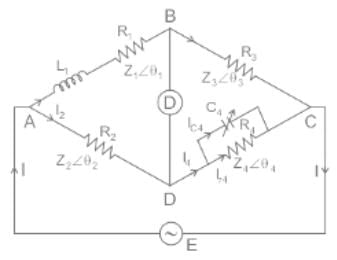
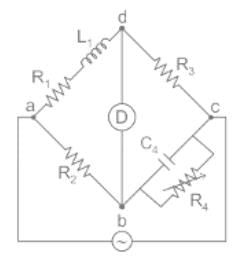
Here R1 and L1 are the unknown resistance and inductance of the coil.
At bridge balance condition,
Z1Z4 = Z2Z3
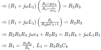
From the above expression, it is clear that unknown inductance (L1) is in terms of known capacitance C4.
From the above expression, it is clear that unknown inductance (L1) is in terms of known capacitance C4.
In case of overdamping, the instrument will become- a)Oscillating
- b)Dead
- c)Fast and sensitive
- d)Slow and lethargic
Correct answer is option 'D'. Can you explain this answer?
In case of overdamping, the instrument will become
a)
Oscillating
b)
Dead
c)
Fast and sensitive
d)
Slow and lethargic
|
|
Aarya Basu answered |
Understanding Overdamping
In electrical engineering, overdamping occurs in systems such as damped harmonic oscillators. This condition affects how an instrument responds to changes in input.
What is Overdamping?
- Overdamping refers to a situation where the damping force is so strong that the system returns to equilibrium without oscillating.
- It contrasts with critically damped and underdamped systems, which may oscillate or return to equilibrium more quickly.
Effects of Overdamping on Instruments
- In overdamped systems, the response time is slowed down significantly.
- Instruments in this condition do not show quick reactions to changes, leading to a sluggish performance.
Why "Slow and Lethargic"?
- Response Time: The instrument takes longer to stabilize after a disturbance. This is because the damping force overpowers the restoring force, causing a gradual return to equilibrium.
- Sensitivity: Overdamped instruments can miss rapid changes in input, making them less sensitive to fluctuations. The slow response can lead to inaccuracies or delays in measurement.
Conclusion
In summary, overdamping results in a system that is slow to respond and lacks the sensitivity required for quick adjustments. Therefore, the correct answer to the question is option 'D': Slow and lethargic. This behavior can be crucial in applications where rapid measurement and response are critical.
Thermal compensation can be provided in a Wheatstone bridge by ________.- a)using more than one resistive sensor
- b)making use of a heat sink
- c)using cooling fans
- d)immersing the circuit into a liquid
Correct answer is option 'A'. Can you explain this answer?
Thermal compensation can be provided in a Wheatstone bridge by ________.
a)
using more than one resistive sensor
b)
making use of a heat sink
c)
using cooling fans
d)
immersing the circuit into a liquid
|
|
Madhavan Nair answered |
Thermal compensation in a Wheatstone bridge refers to the ability to compensate for temperature variations that can affect the accuracy of the bridge circuit. This compensation can be achieved by using more than one resistive sensor in the bridge configuration. Let's discuss this in detail below.
The Wheatstone bridge is a circuit arrangement commonly used for measuring resistance or strain. It consists of four resistive elements connected in a bridge configuration, with an excitation voltage applied across the two opposite nodes of the bridge. The output voltage from the bridge is then proportional to the imbalance between the resistive elements.
However, temperature changes can affect the resistance of the elements in the bridge and introduce errors in the measurement. For example, if the temperature increases, the resistive elements may expand, leading to an increase in their resistance values. This change in resistance can result in an unbalanced bridge and inaccurate measurements.
To compensate for these temperature variations, multiple resistive sensors can be used in the Wheatstone bridge. By having more than one sensor, it becomes possible to measure the temperature at different points and adjust the bridge accordingly. This allows for the cancellation of temperature-induced errors by applying appropriate correction techniques.
The use of multiple resistive sensors provides the ability to measure both the desired quantity (e.g., strain) and the temperature at different locations. By simultaneously measuring the temperature, it becomes possible to determine the effect of temperature on the resistance values and compensate for it.
The compensation technique can involve various methods, such as using a reference temperature or employing temperature-dependent resistors. These methods help in adjusting the bridge output based on the temperature measurements, ensuring accurate measurements even in varying thermal conditions.
In summary, by using more than one resistive sensor in a Wheatstone bridge, thermal compensation can be achieved. This compensation allows for the measurement of temperature variations and adjustment of the bridge output accordingly, ensuring accurate and reliable measurements in different thermal conditions.
Find the false statement.- a)Wheatstone bridge is analogous to superficial level system
- b)A galvanometer with low resistance in series is an ammeter
- c)Wheatstone bridge cannot be used for precision measurement because of the error introduced in contact resistance
- d)Wheatstone bridge is susceptible to high DC
Correct answer is option 'D'. Can you explain this answer?
Find the false statement.
a)
Wheatstone bridge is analogous to superficial level system
b)
A galvanometer with low resistance in series is an ammeter
c)
Wheatstone bridge cannot be used for precision measurement because of the error introduced in contact resistance
d)
Wheatstone bridge is susceptible to high DC
|
|
Avinash Sharma answered |
The false statement is Wheatstone bridge is susceptible to high DC. It is not vulnerable to high DC and can give inaccurate readings if not balanced. The Wheatstone bridge measures resistance from few ohms mega ohms. All the other statements are valid.
Wheatstone bridge consists of _________.- a)4 resistive arms
- b)2 resistive arms
- c)6 resistive arms
- d)8 resistive arms
Correct answer is option 'A'. Can you explain this answer?
Wheatstone bridge consists of _________.
a)
4 resistive arms
b)
2 resistive arms
c)
6 resistive arms
d)
8 resistive arms
|
|
Malavika Saha answered |
Wheatstone bridge is a type of electrical circuit used to measure an unknown resistance value by balancing two legs of a bridge circuit. It consists of four resistive arms, including two fixed resistors and two variable resistors, connected in a diamond shape.
Components of Wheatstone Bridge
The Wheatstone bridge consists of the following components:
1. Four Resistive Arms
The four resistive arms are connected in a diamond shape with two fixed resistors R1 and R2 and two variable resistors R3 and R4. The unknown resistance value is connected to one of the variable resistors.
2. Power Source
A power source is connected to the bridge circuit to provide the necessary voltage for the measurements.
3. Galvanometer
A galvanometer is used to detect the balanced state of the bridge circuit. It measures the current flowing through the circuit and indicates when the bridge is balanced.
Working of Wheatstone Bridge
When the Wheatstone bridge is balanced, the voltage across the galvanometer is zero, indicating that the resistance value of the unknown resistor is equal to the ratio of the two fixed resistors. The formula to calculate the unknown resistance value is:
R3/R4 = R1/R2
If the resistance value of one of the variable resistors is known, the resistance value of the unknown resistor can be calculated by adjusting the other variable resistor until the galvanometer indicates zero voltage.
Conclusion
In conclusion, Wheatstone bridge is a simple and effective circuit used to measure unknown resistance values. It consists of four resistive arms, a power source, and a galvanometer. The balanced state of the bridge circuit is achieved by adjusting the variable resistors until the voltage across the galvanometer is zero.
Dissipation factor of a capacitor can be measured with:- a)Galvanometer
- b)Campbell bridge
- c)Potentiometer
- d)Schering bridge
Correct answer is option 'D'. Can you explain this answer?
Dissipation factor of a capacitor can be measured with:
a)
Galvanometer
b)
Campbell bridge
c)
Potentiometer
d)
Schering bridge
|
|
Prasad Saini answered |
Dissipation factor of a capacitor can be measured with the help of Schering bridge. Schering bridge is a type of AC bridge circuit used to measure the capacitance of a capacitor. Here are the details of how the dissipation factor of a capacitor can be measured with the Schering bridge:
Principle of Schering bridge:
Schering bridge is based on the principle of balancing the unknown capacitive reactance with a known inductive reactance. The bridge is balanced by adjusting the capacitance and inductance of the circuit until the bridge is balanced.
Procedure for measuring the dissipation factor of a capacitor with Schering bridge:
1. Set up the Schering bridge circuit as shown below:

2. Connect the unknown capacitor Cx in the circuit.
3. Set the variable inductor L1 to a known value.
4. Adjust the variable capacitor C1 until the bridge is balanced. At this point, the current through the galvanometer G is zero.
5. Measure the value of the variable capacitor C1 and the variable inductor L1.
6. Repeat the above steps for different values of L1 and C1.
7. Calculate the capacitance of the unknown capacitor Cx using the formula:
Cx = C1 L1 / C2
where C2 is the known capacitance of the standard capacitor.
8. Measure the dissipation factor of the capacitor using the formula:
DF = tan δ = (2πf L1 / R) x (C1/C2)
where f is the frequency of the AC source and R is the resistance of the circuit.
Advantages of Schering bridge:
1. It is a highly accurate method for measuring the capacitance of a capacitor.
2. It is less affected by stray capacitances.
3. It is a simple and easy to use method.
Disadvantages of Schering bridge:
1. It is limited to low capacitance values.
2. It requires an AC source of a fixed frequency.
In conclusion, Schering bridge is a highly accurate and reliable method for measuring the dissipation factor of a capacitor.
Balance condition can be obtained by _________.- a)varying the standard resistance R3
- b)varying the resistance arms R1 and R2
- c)keeping the unknown resistance R4 constant
- d)by making use of a null detector
Correct answer is option 'B'. Can you explain this answer?
Balance condition can be obtained by _________.
a)
varying the standard resistance R3
b)
varying the resistance arms R1 and R2
c)
keeping the unknown resistance R4 constant
d)
by making use of a null detector
|
|
Sarita Yadav answered |
The balance condition in a Wheatstone bridge can be obtained by varying the resistances R1 and R2. The null detector is used for determining the balance condition.
Which is not a source of error in the measurement of low resistance?- a)contact resistance drops at the leads
- b)thermal e.m.f
- c)temperature effect
- d)power dissipation through the circuit
Correct answer is option 'A'. Can you explain this answer?
Which is not a source of error in the measurement of low resistance?
a)
contact resistance drops at the leads
b)
thermal e.m.f
c)
temperature effect
d)
power dissipation through the circuit
|
|
Pooja Patel answered |
As the current flowing through a low resistance circuit is low, the voltage drop across the terminals due to contact and lead resistances is negligible. Thermal e.m.f occurs in a circuit when its temperature increases due to high current flow.
Which instrument is used as the null detector in the Wheatstone bridge?- a)Voltmeter
- b)Ammeter
- c)Galvanometer
- d)Multimeter
Correct answer is option 'C'. Can you explain this answer?
Which instrument is used as the null detector in the Wheatstone bridge?
a)
Voltmeter
b)
Ammeter
c)
Galvanometer
d)
Multimeter
|
|
Sarita Yadav answered |
A galvanometer is used as the null detector in a Wheatstone bridge. The null point means the situation in which no current flows through the circuit. A galvanometer is used to measure the current and determine the voltage between any two ends of the circuit. A galvanometer is used due to its sensitivity, and therefore, even small currents can be measured.
What is connected between the two ends of a Wheatstone bridge?- a)current and voltage source
- b)ammeter and voltmeter
- c)battery and galvanometer
- d)ohmmeter and wattmeter
Correct answer is option 'C'. Can you explain this answer?
What is connected between the two ends of a Wheatstone bridge?
a)
current and voltage source
b)
ammeter and voltmeter
c)
battery and galvanometer
d)
ohmmeter and wattmeter
|
|
Avinash Sharma answered |
A battery is connected between the two ends of the Wheatstone bridge, while a galvanometer is connected between the opposite two ends of the circuit. The ammeter is connected in series with the circuit.
Error due to improper zero adjustment is classified as- a)Environment error
- b)Instrument error
- c)Random error
- d)Operator error
Correct answer is option 'B'. Can you explain this answer?
Error due to improper zero adjustment is classified as
a)
Environment error
b)
Instrument error
c)
Random error
d)
Operator error
|
|
Anirban Gupta answered |
Error due to improper zero adjustment
Improper zero adjustment is classified as Instrument error.
Explanation:
- When the zero adjustment on an instrument is not set properly, it can result in errors in the measurement readings.
- This type of error is considered an instrument error because it is directly related to the calibration and adjustment of the measuring instrument itself.
- Improper zero adjustment can lead to inaccuracies in the measurements taken by the instrument, affecting the overall reliability of the data collected.
- It is important for operators to ensure that the zero adjustment is correctly set before taking any measurements to minimize the risk of errors due to improper zero adjustment.
Therefore, error due to improper zero adjustment is classified as an Instrument error in the field of electrical engineering.
The difference between the indicated value and the true value of a quantity is:- a)Gross error
- b)Absolute error
- c)Dynamic error
- d)Relative error
Correct answer is option 'B'. Can you explain this answer?
The difference between the indicated value and the true value of a quantity is:
a)
Gross error
b)
Absolute error
c)
Dynamic error
d)
Relative error

|
Machine Experts answered |
Absolute error (ε):
The difference between the indicated or measured value and the true or actual value is called absolute error. Also known as a static error.
Absolute error (ε) = Am - At
Where
Am = measured or indicated value
At = true or actual value
Gross error:
- Gross errors are the observational errors that happen due to the lack of observation of the observer.
- These errors vary from observer to observer.
- The gross errors may also occur due to improper selection of the instrument.
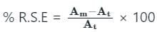
Relative error:
The relative error is the absolute error over the true or actual value.
Relative static error 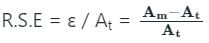
Probable error is a quantity formerly used as a measure of variability which is equal to 0.6745 times the standard deviation.
The equation of balanced Wheatstone bridge is PR = QS.- a)True
- b)False
Correct answer is option 'B'. Can you explain this answer?
The equation of balanced Wheatstone bridge is PR = QS.
a)
True
b)
False
|
|
Yashvi Saha answered |
Explanation:
A Wheatstone bridge is a circuit used to measure electrical resistance. It consists of four resistors connected in a diamond shape, with an input voltage applied across one pair of opposite corners and a detector connected across the other pair of opposite corners. The goal of a Wheatstone bridge is to balance the bridge by adjusting the resistance values until the detector indicates zero voltage, indicating that the bridge is balanced.
The Balanced Wheatstone Bridge Equation:
The equation of a balanced Wheatstone bridge is given by:
PR = QS
Here, P and Q are the resistances on one side of the bridge, and R and S are the resistances on the other side of the bridge. The equation states that the product of the resistances on one side of the bridge is equal to the product of the resistances on the other side of the bridge when the bridge is balanced.
Explanation of the Correct Answer:
The correct answer is option 'B' (False) because the equation stated in the question is incorrect. The correct equation for a balanced Wheatstone bridge is given by:
PR = QS
This equation states that the product of the resistances on one side of the bridge is equal to the product of the resistances on the other side of the bridge when the bridge is balanced.
It is important to note that the equation of a balanced Wheatstone bridge is not PR = QS. This equation does not accurately represent the relationship between the resistances in a balanced Wheatstone bridge.
Therefore, the correct answer is option 'B' (False) as the equation provided in the question is not the correct equation for a balanced Wheatstone bridge.
Identify the definition of sensitivity of a galvanometer from the following.- a)Ratio of unit change in unknown resistance to the deflection in the galvanometer
- b)Ratio of unit change in unknown resistance to twice the deflection in the galvanometer
- c)Ratio of deflection in the galvanometer to the unit change in unknown resistance
- d)Ratio of deflection in the galvanometer to half the unit change in unknown resistance
Correct answer is option 'C'. Can you explain this answer?
Identify the definition of sensitivity of a galvanometer from the following.
a)
Ratio of unit change in unknown resistance to the deflection in the galvanometer
b)
Ratio of unit change in unknown resistance to twice the deflection in the galvanometer
c)
Ratio of deflection in the galvanometer to the unit change in unknown resistance
d)
Ratio of deflection in the galvanometer to half the unit change in unknown resistance
|
|
Sanvi Kapoor answered |
Sensitivity of a galvanometer is defined as the ratio of deflection in the galvanometer to the unit change in unknown resistance. The sensitivity of a galvanometer can be increased by increasing the number of turns, increasing the coil area, or using a strong magnet.
The types of faults in a telephone line are ________.- a)line to line or line to ground
- b)triple line to line or line to ground
- c)open circuit and short circuit
- d)symmetrical and unsymmetrical
Correct answer is option 'A'. Can you explain this answer?
The types of faults in a telephone line are ________.
a)
line to line or line to ground
b)
triple line to line or line to ground
c)
open circuit and short circuit
d)
symmetrical and unsymmetrical
|
|
Kabir Verma answered |
In a telephone line, line to line and line to ground faults occur. Symmetrical, unsymmetrical, open circuit, short circuit, triple line to line, and line to ground faults occur in power systems.
A meter reads 125 V and the true value of the voltage is 125.5 V. Find the static error of the instrument.- a)125/0.5 V
- b)125 V
- c)0.5 V
- d)0.5 / 125 V
Correct answer is option 'C'. Can you explain this answer?
A meter reads 125 V and the true value of the voltage is 125.5 V. Find the static error of the instrument.
a)
125/0.5 V
b)
125 V
c)
0.5 V
d)
0.5 / 125 V
|
|
Sushant Mehta answered |
Understanding Static Error
Static error is the difference between the measured value and the true value of a measurement. In this case, we are measuring voltage.
Given Values
- Measured Voltage (V_measured) = 125 V
- True Voltage (V_true) = 125.5 V
Calculating Static Error
To find the static error, we use the formula:
Static Error = V_measured - V_true
Substituting the values:
- Static Error = 125 V - 125.5 V
- Static Error = -0.5 V
This negative value indicates that the measured voltage is lower than the true voltage by 0.5 V.
Understanding the Options
Now, let's evaluate the options provided:
- a) 125/0.5 V: This option represents a fraction and does not apply here.
- b) 125 V: This is the measured value, not the error.
- c) 0.5 V: This is indeed the absolute value of the static error.
- d) 0.5 / 125 V: This represents a ratio, which is not the correct representation of static error.
Conclusion
Thus, the correct answer is option 'C', which represents the static error of the instrument as 0.5 V. This tells us how much the instrument's reading deviates from the true value.
The bridge used to measure the dielectric loss of an insulator is- a)Anderson bridge
- b)Wien’s bridge
- c)Schering bridge
- d)Wheatstone bridge
Correct answer is option 'C'. Can you explain this answer?
The bridge used to measure the dielectric loss of an insulator is
a)
Anderson bridge
b)
Wien’s bridge
c)
Schering bridge
d)
Wheatstone bridge
|
|
Mainak Pillai answered |
Bridgec)Maxwell bridged)Schering bridge
d) Schering bridge
d) Schering bridge
What is the smallest change in the input signal that can be detected by an instrument called?- a)Accuracy
- b)Precision
- c)Resolution
- d)Sensitivity
Correct answer is option 'C'. Can you explain this answer?
What is the smallest change in the input signal that can be detected by an instrument called?
a)
Accuracy
b)
Precision
c)
Resolution
d)
Sensitivity

|
Vertex Academy answered |
Accuracy: It is the degree of closeness with which the reading approaches the true value of the quantity to be measured.
Precision: It is the measure of reproducibility i.e., given a fixed value of a quantity, precision is a measure of the degree of agreement within a group of measurements.
- The precision of an instrument does not guarantee accuracy
- An instrument with more significant figures has more precision
- Deflection factor is reciprocal of sensitivity
Resolution: The smallest change in output to the change in input is known as resolution. Resolution is the smallest measurable input change.
Sensitivity: It is defined as the ratio of the changes in the output of an instrument to a change in the value of the quantity being measured. It denotes the smallest change in the measured variable to which the instrument responds.
Deflection factor or inverse sensitivity is the reciprocal of sensitivity.
Commonly used D.C. bridges are _________.- a)Schering and Anderson
- b)Maxwell inductance and capacitance
- c)DeSauty and Wagner
- d)Wheatstone and Kelvin
Correct answer is option 'D'. Can you explain this answer?
Commonly used D.C. bridges are _________.
a)
Schering and Anderson
b)
Maxwell inductance and capacitance
c)
DeSauty and Wagner
d)
Wheatstone and Kelvin
|
|
Zoya Sharma answered |
Wheatstone and Kelvin are the commonly used bridges for measuring resistance. Wagner’s and De Sauty’s bridges are used for shielding the circuit.
Heaviside-Campbell bridge is used to measure- a)Self inductance
- b)Mutual inductance
- c)Capacitance
- d)Resistance
Correct answer is option 'B'. Can you explain this answer?
Heaviside-Campbell bridge is used to measure
a)
Self inductance
b)
Mutual inductance
c)
Capacitance
d)
Resistance
|
|
Pooja Patel answered |
Heaviside bridge:
- Heaviside bridge is used to measure the mutual inductance.
- The bridge which measures the unknown mutual inductance regarding mutual inductance such type of bridge is known as the Campbell bridge.
- Mutual inductance is the phenomenon in which the variation of current in one coil induces the current in the nearer coil.
- The bridge is also used for measuring the frequency by adjusting the mutual inductance until the null point is not obtained.
The flux linkage in coil 1 is 3 Wb and it has 500 turns and the current in coil 2 is xA, calculate the value of x if the mutual inductance is 750H.- a)1A
- b)2A
- c)3A
- d)4A
Correct answer is option 'B'. Can you explain this answer?
The flux linkage in coil 1 is 3 Wb and it has 500 turns and the current in coil 2 is xA, calculate the value of x if the mutual inductance is 750H.
a)
1A
b)
2A
c)
3A
d)
4A
|
|
Pooja Patel answered |
We know that mutual inductance is the product of the number of turns in one coil and the flux linkages of that coil, divided by the current in the other coil.
I=3*500/750 = 2A.
I=3*500/750 = 2A.
The flux linkage in coil 1 is 3Wb and it has x turns and the current in coil 2 is 2A, calculate the value of x if the mutual inductance is 750H.- a)300
- b)400
- c)500
- d)700
Correct answer is option 'C'. Can you explain this answer?
The flux linkage in coil 1 is 3Wb and it has x turns and the current in coil 2 is 2A, calculate the value of x if the mutual inductance is 750H.
a)
300
b)
400
c)
500
d)
700
|
|
Pooja Patel answered |
We know that mutual inductance is the product of the number of turns in one coil and the flux linkages of that coil, divided by the current in the other coil.
N = 750*2/3 = 500 turns.
N = 750*2/3 = 500 turns.
Chapter doubts & questions for Bridges and Potentiometers - 6 Months Preparation for GATE Electrical 2025 is part of Electrical Engineering (EE) exam preparation. The chapters have been prepared according to the Electrical Engineering (EE) exam syllabus. The Chapter doubts & questions, notes, tests & MCQs are made for Electrical Engineering (EE) 2025 Exam. Find important definitions, questions, notes, meanings, examples, exercises, MCQs and online tests here.
Chapter doubts & questions of Bridges and Potentiometers - 6 Months Preparation for GATE Electrical in English & Hindi are available as part of Electrical Engineering (EE) exam.
Download more important topics, notes, lectures and mock test series for Electrical Engineering (EE) Exam by signing up for free.
6 Months Preparation for GATE Electrical
675 videos|1297 docs|786 tests
|
|
© EduRev
|
Education Revolution
|


|


Signup to see your scores
go up
within 7 days!
within 7 days!
Takes less than 10 seconds to signup