


All Exams >
Mechanical Engineering >
SSC JE Mechanical Mock Test Series 2026 >
All Questions
All questions of Strength of Materials (SOM) for Mechanical Engineering Exam
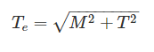
When bending moment M and torque T is applied on a shaft then equivalent torque is- a)M + T
- b)
- c)
- d)
Correct answer is option 'B'. Can you explain this answer?
When bending moment M and torque T is applied on a shaft then equivalent torque is
a)
M + T
b)
c)
d)
|
|
Zoya Sharma answered |
In some applications the shaft are simultaneously subjected to bending moment M and Torque T.
From the simple bending theory equation:
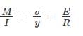
If σb is the maximum bending stresses due to bending moment M on shaft:

Torsion equation:
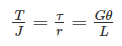
The maximum shear stress developed on the surface of the shaft due to twisting moment T:

Equivalent Bending Moment: 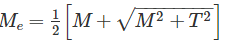
Equivalent Torque:

Which of the following load does not act on the considerable length of the beam?- a)Uniformly distributed
- b)Triangular
- c)Point
- d)Uniformly varying
Correct answer is option 'C'. Can you explain this answer?
Which of the following load does not act on the considerable length of the beam?
a)
Uniformly distributed
b)
Triangular
c)
Point
d)
Uniformly varying
|
|
Yash Patel answered |
Point load is that load which acts over a small distance. Because of concentration over small distance this load can may be considered as acting on a point. Point load is denoted by P and symbol of point load is arrow heading downward (↓).
Uniformly distributed load is that whose magnitude remains uniform throughout the length.
Uniformly Varying Load (Non – Uniformly Distributed Load): It is that load whose magnitude varies along the loading length with a constant rate.
Uniformly varying load is further divided into two types:
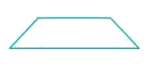
- Triangular Load: whose magnitude is zero at one end of span and increases constantly till the 2nd end of the span.
- Trapezoidal Load: which is acting on the span length in the form of trapezoid. Trapezoid is generally form with the combination of uniformly distributed load (UDL) and triangular load.
The stress at a point in a bar is 200 MPa tensile. Determine the intensity of maximum shear stress in the material.- a)100 MPa
- b)200 MPa
- c)300 MPa
- d)400 MPa
Correct answer is option 'A'. Can you explain this answer?
The stress at a point in a bar is 200 MPa tensile. Determine the intensity of maximum shear stress in the material.
a)
100 MPa
b)
200 MPa
c)
300 MPa
d)
400 MPa
|
|
Sanvi Kapoor answered |
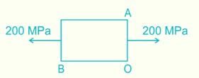
Stress on x face, A(200, 0) and Stress on y face, B(0, 0)
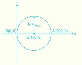
Maximum shear stress = Radius of Mohr circle
τmax= σ/2 = 100 MPa
If the principle stresses on a plane stress problem are S1 = 100 MPa and S2 = 40 MPa then the magnitude of maximum shear stress (MPa) will be:- a)60
- b)50
- c)30
- d)None of these
Correct answer is option 'C'. Can you explain this answer?
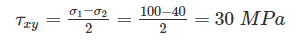
If the principle stresses on a plane stress problem are S1 = 100 MPa and S2 = 40 MPa then the magnitude of maximum shear stress (MPa) will be:
a)
60
b)
50
c)
30
d)
None of these
|
|
Mahi Kaur answered |
In case of plane stress problem, Shear stress is
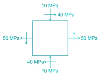
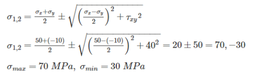
At a point in beam, the principle stresses are 100 N/mm2 and 50 N/mm2. The stress in x-direction is 65 N/mm2. The stress in y-direction will be- a)35 N/mm2
- b)50 N/mm2
- c)85 N/mm2
- d)Cannot be determined
Correct answer is option 'C'. Can you explain this answer?
At a point in beam, the principle stresses are 100 N/mm2 and 50 N/mm2. The stress in x-direction is 65 N/mm2. The stress in y-direction will be
a)
35 N/mm2
b)
50 N/mm2
c)
85 N/mm2
d)
Cannot be determined

|
Pallabi Kulkarni answered |
In beam there is only stress in x and y direction, there is no stress in z direction.
σ1 + σ2 = σx + σy
100 + 50 = 65 + σy
σy = 150 – 65 = 85 N/mm2
If section modulus of a beam is increased, the bending stress in the beam will:- a)Not change
- b)Increase
- c)Decrease
- d)Become zero
Correct answer is option 'C'. Can you explain this answer?
If section modulus of a beam is increased, the bending stress in the beam will:
a)
Not change
b)
Increase
c)
Decrease
d)
Become zero
|
|
Lavanya Menon answered |
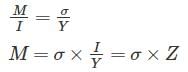
Bending Moment Equation
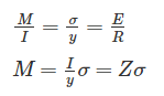
For the constant bending moment: σ ∝ 1/Z
So, bending stress is inversely proportional to the Section Modulus 'YH
Which material has highest value of poison’s ratio?- a)Elastic Rubber
- b)Wood
- c)Copper
- d)Steel
Correct answer is option 'A'. Can you explain this answer?
Which material has highest value of poison’s ratio?
a)
Elastic Rubber
b)
Wood
c)
Copper
d)
Steel
|
|
Rhea Reddy answered |
Elastic Rubber: 0.5
Wood: Because wood is orthotropic, 12 constants are required to describe elastic behaviour: 3 moduli of elasticity, 3 moduli of rigidity, and 6 Poisson’s ratios (vary from 0.02 to 0.47). These elastic constants vary within and among species and with moisture content and specific gravity.
Copper: 0.33
Steel: 0.27 - 0.30

 =25N/mm2=25MPa$
A closed coil helical spring has 25 coils. If five coils of this springs are removed by cutting, the stiffness of the modified spring will- a)Increase to 1.25 times
- b)Increase to 1.5 times
- c)Reduce to 0.66 times
- d)Remain unaffected
Correct answer is option 'A'. Can you explain this answer?
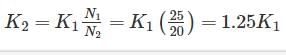
A closed coil helical spring has 25 coils. If five coils of this springs are removed by cutting, the stiffness of the modified spring will
a)
Increase to 1.25 times
b)
Increase to 1.5 times
c)
Reduce to 0.66 times
d)
Remain unaffected
|
|
Pankaj Joshi answered |
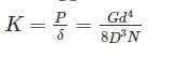
K1N1 = K2N2
The equivalent length of a column of length L having one end fixed and the other end free is- a)2L
- b)L
- c)L/2
- d)L/√2
Correct answer is option 'A'. Can you explain this answer?
The equivalent length of a column of length L having one end fixed and the other end free is
a)
2L
b)
L
c)
L/2
d)
L/√2
|
|
Jhanvi Datta answered |
Effective length of columns under different end conditions are:
1. For both ends hinged: Le = L
2. One end fixed and another end free: Le = 2L
3. Both ends fixed = Le= 
4. One end fixed and other is hinges: Le= 
Circumferential and longitudinal strains in cylindrical boiler under internal steam pressure, are ε1 and ε2 respectively. Change in volume of the boiler cylinder per unit volume will be- a)ε1 +2 ε2
- b)ε1 ε22
- c)2ε1 + ε2
- d)ε12 ε2
Correct answer is option 'C'. Can you explain this answer?
Circumferential and longitudinal strains in cylindrical boiler under internal steam pressure, are ε1 and ε2 respectively. Change in volume of the boiler cylinder per unit volume will be
a)
ε1 +2 ε2
b)
ε1 ε22
c)
2ε1 + ε2
d)
ε12 ε2
|
|
Asha Basu answered |
Caused by the deformation of the boiler due to the internal pressure.
Circumferential strain refers to the strain or elongation that occurs in the circumferential direction of the cylindrical boiler. This strain is caused by the radial expansion of the boiler walls due to the internal steam pressure. The circumferential strain can be calculated using the formula:
ε_c = (P * r) / (E * t)
Where ε_c is the circumferential strain, P is the internal steam pressure, r is the radius of the boiler, E is the modulus of elasticity of the material, and t is the thickness of the boiler walls.
Longitudinal strain refers to the strain or elongation that occurs in the longitudinal direction of the cylindrical boiler. This strain is caused by the axial expansion or contraction of the boiler walls due to the internal steam pressure. The longitudinal strain can be calculated using the formula:
ε_l = (P * r) / (2 * E * t)
Where ε_l is the longitudinal strain, P is the internal steam pressure, r is the radius of the boiler, E is the modulus of elasticity of the material, and t is the thickness of the boiler walls.
Both circumferential and longitudinal strains are important factors to consider in the design and analysis of cylindrical boilers, as excessive strains can lead to deformation, failure, or leakage. Therefore, engineers must ensure that the materials and dimensions of the boiler are suitable to withstand the expected internal steam pressure.
When the shear force diagram is a parabolic curve between two points, it indicates that there is a- a)point load at the two points
- b)no loading between the two points
- c)uniformly distributed load between the two points
- d)uniformly varying load between the two points
Correct answer is option 'D'. Can you explain this answer?
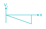
When the shear force diagram is a parabolic curve between two points, it indicates that there is a
a)
point load at the two points
b)
no loading between the two points
c)
uniformly distributed load between the two points
d)
uniformly varying load between the two points
|
|
Disha Nambiar answered |
The general relationship between the shear force diagram, bending moment diagram and loading diagram will be:
1. Shear force diagram is 1o higher than loading diagram.
2. Bending moment diagram is 1o higher than shear force diagram.
3. For the uniformly varying load on the beam, the shear force diagram is parabolic in nature.
4. For the uniformly varying load on the beam, the bending moment diagram is also parabolic but is 1o higher than shear force diagram.
Mohr’s circle can be used to determine the following stress on an inclined surface:A. Principal stressB. Normal stressC. Tangential stressD. Maximum shear stress- a)Only A
- b)Only B
- c)Only C
- d)A, B, C and D
Correct answer is option 'D'. Can you explain this answer?
Mohr’s circle can be used to determine the following stress on an inclined surface:
A. Principal stress
B. Normal stress
C. Tangential stress
D. Maximum shear stress
a)
Only A
b)
Only B
c)
Only C
d)
A, B, C and D
|
|
Pritam Das answered |
Mohr circle is a graphical representation of plane stress which helps in determining the relationships between normal and shear stresses acting on any inclined plane at a point in a stressed body.
Mohr’s circle of stresses is a graphical method of finding normal, tangential and resultant stresses on an oblique plane.
A cantilever beam is deflected by δ due to load P. If length of beam is doubled, the deflection compared to earlier case will be changed by a factor of:- a)2
- b)1/2
- c)1/8
- d)8
Correct answer is option 'D'. Can you explain this answer?
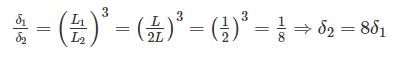
A cantilever beam is deflected by δ due to load P. If length of beam is doubled, the deflection compared to earlier case will be changed by a factor of:
a)
2
b)
1/2
c)
1/8
d)
8
|
|
Sinjini Nambiar answered |
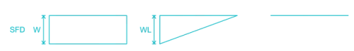
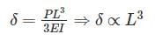
Deflection of cantilever beam having concentrated load at the free end is given by

Use of strain rosette is to:- a)Measure linear strain
- b)Measure shear strain
- c)Measure volumetric strain
- d)Relieve strain
Correct answer is option 'A'. Can you explain this answer?
Use of strain rosette is to:
a)
Measure linear strain
b)
Measure shear strain
c)
Measure volumetric strain
d)
Relieve strain

|
Sarthak Kulkarni answered |
Strain rosette can be defined as the arrangement strain gauge oriented at different angles. It only measures strain in one direction, to get principal strains, it is necessary to use a strain rosette.
Depending on the arrangement of strain gauges, strain rosettes are classified in to:-
1. Rectangular strain gauge rosette
2. Delta strain gauge rosette
3. Star strain gauge rosette
The resistance per unit area, offered by a body against deformation is known as:- a)Load
- b)Pressure
- c)Stress
- d)Strain
Correct answer is option 'C'. Can you explain this answer?
The resistance per unit area, offered by a body against deformation is known as:
a)
Load
b)
Pressure
c)
Stress
d)
Strain

|
Asha Deshpande answered |
Stress is also known as resisting force per unit area.
In other words some times it may be regarded as pressure.
In biological terms stress is the response of body to external environmental conditions.
These external environmental conditions may be good or bad.
It is an internal force.
Maximum Shear strain Energy theory was postulated by:- a)Tresca
- b)St Venant
- c)Rankine
- d)Von-mises
Correct answer is option 'D'. Can you explain this answer?
Maximum Shear strain Energy theory was postulated by:
a)
Tresca
b)
St Venant
c)
Rankine
d)
Von-mises
|
|
Siddharth Menon answered |
. Maximum Principal stress theory was postulated by Rankine. It is suitable for brittle materials.
2. Maximum Principal strain theory was postulated by St Venant. This theory is not accurate for brittle and ductile materials both.
3. Maximum Shear stress theory was postulated by Tresca. This theory is suitable for ductile materials. Its results are the safest.
4. Maximum shear strain energy theory was postulated by Von-mises. Its results in case of pure shear are the accurate for ductile materials.
For beams of uniform strength, if depth is constant, then- a)Width is directly proportional to bending moment
- b)Width is directly proportional to square root of bending moment
- c)Width is directly proportional to three times the square root of bending moment
- d)Width is inversely proportional to bending moment
Correct answer is option 'A'. Can you explain this answer?
For beams of uniform strength, if depth is constant, then
a)
Width is directly proportional to bending moment
b)
Width is directly proportional to square root of bending moment
c)
Width is directly proportional to three times the square root of bending moment
d)
Width is inversely proportional to bending moment
|
|
Sanskriti Chakraborty answered |
Using Flexural Formula
M ∝ Z

d is constant
M ∝ b (width)
Assume that young's modulus of a wire of length L and radius 'r' is Y. If length is reduced to L/2 and radius r/2 then what will be its young's modulus?- a)halved
- b)doubled
- c)unaffected
- d)One-fourth of its original value
Correct answer is option 'C'. Can you explain this answer?
Assume that young's modulus of a wire of length L and radius 'r' is Y. If length is reduced to L/2 and radius r/2 then what will be its young's modulus?
a)
halved
b)
doubled
c)
unaffected
d)
One-fourth of its original value
|
|
Gopal Choudhury answered |
Young's is a property of the material of construction of a wire. It depends only on the nature of the material used for making the wire.
Young's modulus does not depend on the physical dimensions such as the length and diameter of wire. Thus there will be no change in Young's modulus.
A steel rod of 1 sq. cm. cross sectional area is 100 cm long and has a Young’s modulus of elasticity 2 × 10⁶ kgf/cm2. It is subjected to an axial pull of 2000 kgf. The elongation of the rod will be- a)0.05 cm
- b)0.1 cm
- c)0.15 cm
- d)0.20 cm
Correct answer is option 'B'. Can you explain this answer?
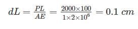
A steel rod of 1 sq. cm. cross sectional area is 100 cm long and has a Young’s modulus of elasticity 2 × 10⁶ kgf/cm2. It is subjected to an axial pull of 2000 kgf. The elongation of the rod will be
a)
0.05 cm
b)
0.1 cm
c)
0.15 cm
d)
0.20 cm
|
|
Meera Bose answered |
Change in length:
The ratio of moment of inertia of circular plate to that of square plate of equal depth is:- a)less than 1
- b)Equal to 1
- c)Greater than 1
- d)None of these
Correct answer is option 'A'. Can you explain this answer?
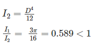
The ratio of moment of inertia of circular plate to that of square plate of equal depth is:
a)
less than 1
b)
Equal to 1
c)
Greater than 1
d)
None of these
|
|
Gayatri Dasgupta answered |
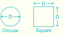
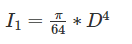
Moment of inertia (I1) of circular plate of diameter “D” is given by:
. 
Moment of inertia (I2) of square plate of side equal to diameter “D” of circular plate is given by:
The diameter of shaft A is twice the diameter of shaft B and both are made of the same material. Assuming both the shafts to rotate at the same speed, the maximum power transmitted by B is- a)The same as that of A
- b)Half of A
- c)1/8th of A
- d)1/4th of A
Correct answer is option 'C'. Can you explain this answer?
The diameter of shaft A is twice the diameter of shaft B and both are made of the same material. Assuming both the shafts to rotate at the same speed, the maximum power transmitted by B is
a)
The same as that of A
b)
Half of A
c)
1/8th of A
d)
1/4th of A
|
|
Jithin Choudhury answered |
Shaft A and Shaft B
- Shaft A has a diameter twice that of Shaft B.
- Both shafts are made of the same material.
- Both shafts rotate at the same speed.
Power Transmitted
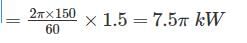
The power transmitted by a rotating shaft is given by the equation:
Power (P) = (Torque (T) × Angular velocity (ω)) / 1000
Here, torque is the force applied perpendicular to the shaft multiplied by the radius of the shaft, and angular velocity is the rate at which the shaft rotates.
Comparison of Shafts A and B
Since both shafts are rotating at the same speed, the angular velocity (ω) is the same for both.
Let the diameter of Shaft B be D, then the diameter of Shaft A is 2D.
The radius of Shaft B is D/2, and the radius of Shaft A is (2D)/2 = D.
Torque Calculation
The torque transmitted by a shaft is directly proportional to the radius of the shaft.
Since both shafts are made of the same material, the torque transmitted by Shaft A is directly proportional to the radius of Shaft A, and the torque transmitted by Shaft B is directly proportional to the radius of Shaft B.
Hence, the torque transmitted by Shaft A is 2 times the torque transmitted by Shaft B.
Power Calculation
Using the equation for power, we have:
Power (A) = (Torque (A) × Angular velocity (ω)) / 1000
Power (B) = (Torque (B) × Angular velocity (ω)) / 1000
Since the angular velocity is the same for both shafts, it can be canceled out.
Therefore, Power (A) = Torque (A) / 1000
Power (B) = Torque (B) / 1000
Substituting the torque values, we have:
Power (A) = (2 × Torque (B)) / 1000
Since the torque transmitted by Shaft A is 2 times the torque transmitted by Shaft B, we can rewrite the equation as:
Power (A) = (2 × 2 × Torque (B)) / 1000
Power (A) = (4 × Torque (B)) / 1000
This means that the power transmitted by Shaft A is 4 times the power transmitted by Shaft B.
Conclusion
Hence, the maximum power transmitted by Shaft B is 1/4th of the power transmitted by Shaft A. Therefore, the correct answer is option 'd', 1/4th of A.
- Shaft A has a diameter twice that of Shaft B.
- Both shafts are made of the same material.
- Both shafts rotate at the same speed.
Power Transmitted
The power transmitted by a rotating shaft is given by the equation:
Power (P) = (Torque (T) × Angular velocity (ω)) / 1000
Here, torque is the force applied perpendicular to the shaft multiplied by the radius of the shaft, and angular velocity is the rate at which the shaft rotates.
Comparison of Shafts A and B
Since both shafts are rotating at the same speed, the angular velocity (ω) is the same for both.
Let the diameter of Shaft B be D, then the diameter of Shaft A is 2D.
The radius of Shaft B is D/2, and the radius of Shaft A is (2D)/2 = D.
Torque Calculation
The torque transmitted by a shaft is directly proportional to the radius of the shaft.
Since both shafts are made of the same material, the torque transmitted by Shaft A is directly proportional to the radius of Shaft A, and the torque transmitted by Shaft B is directly proportional to the radius of Shaft B.
Hence, the torque transmitted by Shaft A is 2 times the torque transmitted by Shaft B.
Power Calculation
Using the equation for power, we have:
Power (A) = (Torque (A) × Angular velocity (ω)) / 1000
Power (B) = (Torque (B) × Angular velocity (ω)) / 1000
Since the angular velocity is the same for both shafts, it can be canceled out.
Therefore, Power (A) = Torque (A) / 1000
Power (B) = Torque (B) / 1000
Substituting the torque values, we have:
Power (A) = (2 × Torque (B)) / 1000
Since the torque transmitted by Shaft A is 2 times the torque transmitted by Shaft B, we can rewrite the equation as:
Power (A) = (2 × 2 × Torque (B)) / 1000
Power (A) = (4 × Torque (B)) / 1000
This means that the power transmitted by Shaft A is 4 times the power transmitted by Shaft B.
Conclusion
Hence, the maximum power transmitted by Shaft B is 1/4th of the power transmitted by Shaft A. Therefore, the correct answer is option 'd', 1/4th of A.
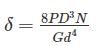
A body having weight of 1000 N is dropped form a height of 10 cm over a close-coiled helical spring of stiffness 200 N/cm. The resulting deflection of spring is nearly- a)5 cm
- b)16 cm
- c)35 cm
- d)100 cm
Correct answer is option 'B'. Can you explain this answer?
A body having weight of 1000 N is dropped form a height of 10 cm over a close-coiled helical spring of stiffness 200 N/cm. The resulting deflection of spring is nearly
a)
5 cm
b)
16 cm
c)
35 cm
d)
100 cm
|
|
Sravya Rane answered |
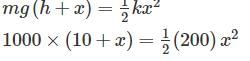
100 +10x - x2 = 0
x2 -10x - 100 = 0

x = 16 cm
A metal pipe of 1 m diameter contains a fluid having a pressure of 10 kgf/cm2. If the permissible tensile stress in the metal is 200 kgf/cm2, then the thickness of the metal required for making the pipe would be- a)5 mm
- b)10 mm
- c)20 mm
- d)25 mm
Correct answer is option 'D'. Can you explain this answer?
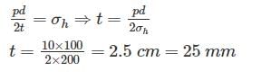
A metal pipe of 1 m diameter contains a fluid having a pressure of 10 kgf/cm2. If the permissible tensile stress in the metal is 200 kgf/cm2, then the thickness of the metal required for making the pipe would be
a)
5 mm
b)
10 mm
c)
20 mm
d)
25 mm
|
|
Shounak Saini answered |
As in thin cylinder shell:
Longitudinal stress = Half of circumferential stress
∴ circumferential stress ≤ Permissible stress
Slenderness ratio of a long column is- a)Area of cross-section divided by radius of gyration
- b)Area of cross-section divided by least radius of gyration
- c)Radius of gyration divided by area of cross-section
- d)Length of column divided by least radius of gyration
Correct answer is option 'D'. Can you explain this answer?
Slenderness ratio of a long column is
a)
Area of cross-section divided by radius of gyration
b)
Area of cross-section divided by least radius of gyration
c)
Radius of gyration divided by area of cross-section
d)
Length of column divided by least radius of gyration
|
|
Anjali Shah answered |
Slenderness ratio ( λ ) of long column is defined as the ratio of Effective length of column to its least radius of gyration.

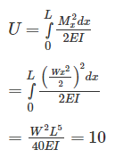
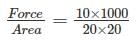
A rectangular bar of cross sectional area 10000 mm2 is subjected to an axial load of 40 kN. Determine the normal stress on the section which is inclined at an angle of 30° with normal cross-section of the bar.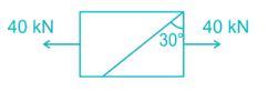
- a)1.5 MPa
- b)3 MPa
- c)1.7 MPa
- d)4.5 MPa
Correct answer is option 'B'. Can you explain this answer?
A rectangular bar of cross sectional area 10000 mm2 is subjected to an axial load of 40 kN. Determine the normal stress on the section which is inclined at an angle of 30° with normal cross-section of the bar.
a)
1.5 MPa
b)
3 MPa
c)
1.7 MPa
d)
4.5 MPa
|
|
Snehal Tiwari answered |
\(\sigma = \frac{P}{A} = \frac{{40 \times 1000}}{{1000}} = 4\;MPa\)
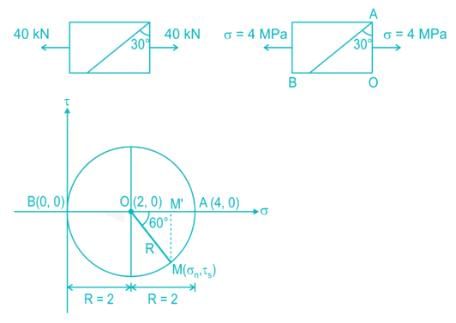
Normal stress on inclined plane:
σn = BM' = R + R cos 60° = R(1 + cos 60)
σn = 2(1 + 0.5) = 3 MPa
Some more important calculations which may be asked in exams:
Shear stress on inclined plane:
\({\tau _s} = R\sin 60^\circ = \frac{{2 \times \sqrt 3 }}{2} = 1.732\;MPa\)
Maximum principal stress, σ1 = 4 MPa (θ = 0°)
Minimum principal stress, σ2 = 0 MPa (θ = 90°)
Radius of the Mohr circle R = σ1/2 = 2 MPa
Maximum shear stress, τmax = R = 2 MPa (θ = 45°)
In the case of bi-axial state of normal stresses, the normal stress on 45° plane is equal to- a)the sum of the normal stresses
- b)
difference of the normal stresses
- c)half the sum of the normal stresses
- d)half the difference of the normal stresses
Correct answer is option 'C'. Can you explain this answer?
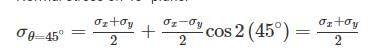
In the case of bi-axial state of normal stresses, the normal stress on 45° plane is equal to
a)
the sum of the normal stresses
b)
difference of the normal stresses
c)
half the sum of the normal stresses
d)
half the difference of the normal stresses
|
|
Raghavendra Dasgupta answered |
In the case of bi-axial state of normal stresses:
Normal stress on an inclined plane:
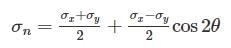
Shear Stress on an inclined plane:
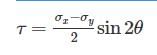
Normal stress on 45° plane:
Young’s modulus of elasticity is defined as the ratio of which of the following?- a)Lateral strain to longitudinal stress
- b)Lateral strain to longitudinal strain
- c)Longitudinal stress to longitudinal strain
- d)Shear stress to shear strain
Correct answer is option 'C'. Can you explain this answer?
Young’s modulus of elasticity is defined as the ratio of which of the following?
a)
Lateral strain to longitudinal stress
b)
Lateral strain to longitudinal strain
c)
Longitudinal stress to longitudinal strain
d)
Shear stress to shear strain
|
|
Dishani Desai answered |
Understanding Young's Modulus of Elasticity
Young's modulus of elasticity is a fundamental property of materials that quantifies their ability to deform elastically (i.e., non-permanently) when subjected to stress. It is crucial in mechanical engineering and materials science.
Definition
Young's modulus (E) is defined as the ratio of:
- Longitudinal Stress (force per unit area) to
- Longitudinal Strain (relative change in length).
Mathematical Representation
E = Longitudinal Stress / Longitudinal Strain
This relationship emphasizes how much a material will stretch or compress under a given load.
Why Option 'C' is Correct
- Longitudinal Stress: This is the force applied per unit area along the length of the material. It is often expressed in Pascals (Pa).
- Longitudinal Strain: This is the change in length divided by the original length of the material, indicating how much the material has deformed under the applied stress.
The ratio of these two quantities provides a measure of stiffness or rigidity of a material. A higher Young's modulus indicates a stiffer material that deforms less under stress, while a lower value indicates a more flexible material.
Other Options Explained
- Option A: Lateral strain to longitudinal stress is related to Poisson's ratio, not Young's modulus.
- Option B: Lateral strain to longitudinal strain does not define any modulus of elasticity.
- Option D: Shear stress to shear strain defines the shear modulus, not Young's modulus.
In summary, Young's modulus is a key parameter in understanding material behavior under load, making option 'C' the correct choice.
The total area under the stress-strain curve of a mild steel specimen tested up to failure under tension is a measure of its:- a)Breaking strength
- b)Toughness
- c)Hardness
- d)Stiffness
Correct answer is option 'B'. Can you explain this answer?
The total area under the stress-strain curve of a mild steel specimen tested up to failure under tension is a measure of its:
a)
Breaking strength
b)
Toughness
c)
Hardness
d)
Stiffness
|
|
Divyansh Goyal answered |
Strength is defined as the ability of the material to resist, without rupture, external forces causing various types of stresses. Breaking strength is the ability of a material to withstand a pulling or tensile force.
Toughness is defined as the ability of the material to absorb energy before fracture takes place. In other words, toughness is the energy for failure by fracture. Toughness is measured by a quantity called modulus of toughness. Modulus of toughness is the total area under a stress-strain curve in tension test, which also represents the work done to fracture the specimen.
Hardness is defined as the resistance of a material to penetration or permanent deformation. It usually indicates resistance to abrasion, scratching, cutting or shaping.
Stiffness or rigidity is defined as the ability of the material to resist deformation under the action of external load. Modulus of elasticity is the measure of stiffness.
The neutral axis of a beam is subjected to _________ stress.- a)Zero
- b)Maximum tensile
- c)Minimum tensile
- d)Maximum compressive
Correct answer is option 'A'. Can you explain this answer?
The neutral axis of a beam is subjected to _________ stress.
a)
Zero
b)
Maximum tensile
c)
Minimum tensile
d)
Maximum compressive
|
|
Athul Kumar answered |
The neutral axis is an axis in the cross-section of a beam (a member resisting bending) or shaft along which there are no longitudinal stresses or strains. If the section is symmetric, isotropic and is not curved before a bend occurs, then the neutral axis is at the geometric centroid. All fibers on one side of the neutral axis are in a state of tension, while those on the opposite side are in compression.
 Power=
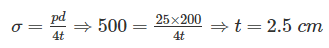
A spherical vessel with an inside diameter of 2 m is made of material having an allowable stress in tension of 500 kg/cm2. The thickness of a shell to with stand a pressure of 25 kg/cm2 should be:- a)5 cm
- b)10 cm
- c)2.5 cm
- d)1.25 cm
Correct answer is option 'C'. Can you explain this answer?
A spherical vessel with an inside diameter of 2 m is made of material having an allowable stress in tension of 500 kg/cm2. The thickness of a shell to with stand a pressure of 25 kg/cm2 should be:
a)
5 cm
b)
10 cm
c)
2.5 cm
d)
1.25 cm
|
|
Lekshmi Das answered |
Allowable stress in spherical pressure vessel:
A tensile test is performed on a round bar. After fracture it has been found that the diameter remains approximately same at fracture. The material under test was- a)Mild steel
- b)Cast iron
- c)Wrought iron
- d)Copper
Correct answer is option 'B'. Can you explain this answer?
A tensile test is performed on a round bar. After fracture it has been found that the diameter remains approximately same at fracture. The material under test was
a)
Mild steel
b)
Cast iron
c)
Wrought iron
d)
Copper
|
|
Pankaj Kapoor answered |
In Brittle materials under tension test undergoes brittle fracture i.e there failure plane is 90° to the axis of load and there is no elongation in the rod that’s why the diameter remains same before and after the load. Example: Cast Iron, concrete etc
But in case of ductile materials, material first elongate and then fail, their failure plane is 45° to the axis of the load. After failure cup-cone failure is seen. Example Mild steel, high tensile steel etc.
Select the proper sequence1. Proportional Limit 2. Elastic limit3. Yielding 4. Failure- a)2, 3, 1, 4
- b)2, 1, 3, 4
- c)1, 3, 2, 4
- d)1, 2, 3, 4
Correct answer is option 'D'. Can you explain this answer?
Select the proper sequence
1. Proportional Limit 2. Elastic limit
3. Yielding 4. Failure
a)
2, 3, 1, 4
b)
2, 1, 3, 4
c)
1, 3, 2, 4
d)
1, 2, 3, 4
|
|
Abhay Kapoor answered |
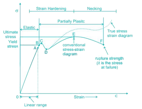
- So it is evident form the graph that the strain is proportional to stress or elongation is proportional to the load giving a straight line relationship. This law of proportionality is valid upto a point A. Point A is known as the limit of proportionality or the proportionality limit.
- For a short period beyond the point A, the material may still be elastic in the sense that the deformations are completely recovered when the load is removed. The limiting point B is termed as Elastic Limit.
- Beyond the elastic limit plastic deformation occurs and strains are not totally recoverable. There will be thus permanent deformation or permanent set when load is removed. These two points are termed as upper and lower yield points respectively. The stress at the yield point is called the yield strength.
- A further increase in the load will cause marked deformation in the whole volume of the metal. The maximum load which the specimen can with stand without failure is called the load at the ultimate strength. The highest point ‘E' of the diagram corresponds to the ultimate strength of a material.
- Beyond point E, the bar begins to form neck. The load falling from the maximum until fracture occurs at F.
The major and minor principal stresses at a point are 3Mpa and -3Mpa respectively. The maximum shear stress at the point is- a)Zero
- b)3Mpa
- c)6Mpa
- d)None of these
Correct answer is option 'B'. Can you explain this answer?
The major and minor principal stresses at a point are 3Mpa and -3Mpa respectively. The maximum shear stress at the point is
a)
Zero
b)
3Mpa
c)
6Mpa
d)
None of these
|
|
Aaditya Jain answered |
Analysis:
Given Data:
- Major principal stress (σ1) = 3 MPa
- Minor principal stress (σ2) = -3 MPa
Formula:
- Maximum shear stress (τmax) = (σ1 - σ2) / 2
Calculations:
- Substituting the given values in the formula:
τmax = (3 - (-3)) / 2
τmax = 6 / 2
τmax = 3 MPa
Conclusion:
The maximum shear stress at the point is 3 MPa (Option B).
What is the limit to Poisson's ratio?- a)0.1
- b)0.2
- c)0.3
- d)None of these
Correct answer is option 'D'. Can you explain this answer?
What is the limit to Poisson's ratio?
a)
0.1
b)
0.2
c)
0.3
d)
None of these
|
|
Subhankar Khanna answered |
Limit of poisons ratio varies between -1 to 0.5.
μ = 0.5 for rubber.
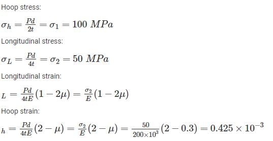
Hoops stress and longitudinal stress in a boiler shell under internal pressure are 100 MN/m2 and 50 MN/m2 respectively. Young’s modulus of elasticity and Poisson’s ratio of the shell material are 200 GN/m2 and 0.3 respectively. The hoop strain in boiler shell is- a)0.425 × 10⁻³
- b)0.5 × 10⁻³
- c)0.585 × 10⁻³
- d)0.75 × 10⁻³
Correct answer is option 'A'. Can you explain this answer?
Hoops stress and longitudinal stress in a boiler shell under internal pressure are 100 MN/m2 and 50 MN/m2 respectively. Young’s modulus of elasticity and Poisson’s ratio of the shell material are 200 GN/m2 and 0.3 respectively. The hoop strain in boiler shell is
a)
0.425 × 10⁻³
b)
0.5 × 10⁻³
c)
0.585 × 10⁻³
d)
0.75 × 10⁻³
|
|
Bhargavi Sarkar answered |
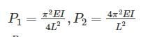
With one fixed end and other free end, a column of length L buckles at load, P1. Another column of same length and same cross-section fixed at both ends buckles at load P2. Value of P2/P1 is- a)1
- b)2
- c)4
- d)16
Correct answer is option 'D'. Can you explain this answer?
With one fixed end and other free end, a column of length L buckles at load, P1. Another column of same length and same cross-section fixed at both ends buckles at load P2. Value of P2/P1 is
a)
1
b)
2
c)
4
d)
16
|
|
Kalyan Chakraborty answered |
The maximum load at which the column tends to have lateral displacement or tends to buckle is known as buckling or crippling load. Load columns can be analysed with the Euler’s column formulas can be given as
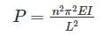
- For both end hinged, n = 1
- For one end fixed and other free, n = ½
- For both end fixed, n = 2
- For one end fixed and other hinged, n = √2

For a thin spherical shell subjected to internal pressure, the ratio of volumetric strain to diametrical strain is _____.- a)5 : 4
- b)3 : 2
- c)2 : 1
- d)3 : 1
Correct answer is option 'D'. Can you explain this answer?
For a thin spherical shell subjected to internal pressure, the ratio of volumetric strain to diametrical strain is _____.
a)
5 : 4
b)
3 : 2
c)
2 : 1
d)
3 : 1
|
|
Yash Joshi answered |
Solution:
The volumetric strain (εv) is defined as the change in volume per unit original volume, while the diametrical strain (εd) is defined as the change in diameter per unit original diameter.
Let's consider a thin spherical shell with an internal pressure.
Step 1: Deriving the formulas
The formula for volumetric strain is given by:
εv = ΔV / V
where ΔV is the change in volume and V is the original volume.
The change in volume can be calculated using the formula:
ΔV = 4/3π (R2^3 - R1^3)
where R1 is the initial radius and R2 is the final radius.
Substituting the value of ΔV in the volumetric strain formula, we get:
εv = 4/3π (R2^3 - R1^3) / (4/3π R1^3)
Simplifying the equation, we get:
εv = (R2^3 - R1^3) / R1^3
The formula for diametrical strain is given by:
εd = ΔD / D
where ΔD is the change in diameter and D is the original diameter.
The change in diameter can be calculated using the formula:
ΔD = 2(R2 - R1)
Substituting the value of ΔD in the diametrical strain formula, we get:
εd = 2(R2 - R1) / 2R1
Simplifying the equation, we get:
εd = (R2 - R1) / R1
Step 2: Evaluating the ratio
To find the ratio of volumetric strain to diametrical strain, we divide the equation for volumetric strain by the equation for diametrical strain:
(εv / εd) = [(R2^3 - R1^3) / R1^3] / [(R2 - R1) / R1]
Simplifying the equation, we get:
(εv / εd) = [(R2^3 - R1^3) / (R2 - R1)] * (R1 / R1)
(εv / εd) = (R2^3 - R1^3) / (R2 - R1)
Since the shell is thin, R2 is very close to R1, so we can approximate R2 - R1 as ΔR.
(εv / εd) = (R1^3 + R1^2ΔR + R1ΔR^2 - R1^3) / ΔR
(εv / εd) = (R1^2ΔR + R1ΔR^2) / ΔR
(εv / εd) = (R1^2 + R1ΔR) / 1
(εv / εd) = R1(R1 + ΔR) / ΔR
As ΔR approaches zero (since the shell is thin), the ratio becomes:
(εv / εd) = R1 / 0
Therefore, the ratio of volumetric strain to diametrical strain is undefined if the shell is infinitely thin. However, in practice, for thin shells,
If a prismatic bar be subjected to an axial tensile stress σ, then shear stress induced on a plane inclined at θ with the axis will be- a)

- b)

- c)

- d)

Correct answer is option 'A'. Can you explain this answer?
If a prismatic bar be subjected to an axial tensile stress σ, then shear stress induced on a plane inclined at θ with the axis will be
a)
b)
c)
d)
|
|
Meghana Desai answered |
Pn = The component of force P, normal to section FG = P cos θ
Pt = The component of force P, along the surface of the section FG (tangential to the surface FG) = P sin θ
σn = Normal Stress across the section FG
σn=σcos2θσn=σcos2θ
σt = Tangential/Shear Stress across the section FG
The radius of Mohr’s circle for two equal and unlike principal stresses of magnitude “p” is:- a)p
- b)

- c)Zero
- d)None of the above
Correct answer is option 'A'. Can you explain this answer?
The radius of Mohr’s circle for two equal and unlike principal stresses of magnitude “p” is:
a)
p
b)
c)
Zero
d)
None of the above
|
|
Ashish Pillai answered |
Radius of Mohr’s circle is given by:
r=
At principal plane, σx = σ1, σy = σ2
τxy = 0
r= 
σ1 = p , σ2 = -p
r= 
r = p
The correct relation between Modulus of elasticity (E), Shear Modulus (G) and Bulk modulus (K) is:- a)
- b)
- c)
- d)
Correct answer is option 'D'. Can you explain this answer?
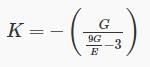
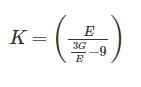
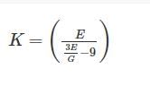
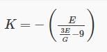
The correct relation between Modulus of elasticity (E), Shear Modulus (G) and Bulk modulus (K) is:
a)
b)
c)
d)
|
|
Sagarika Mukherjee answered |
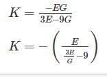
Relation between Modulus of elasticity (E), Shear Modulus (G) and Bulk modulus (K) is given by:
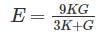
Now, rewriting the equation as follows:
3KE + GE = 9KG
3KE – 9KG = - GE
K(3E – 9G) = - GE
The temperature stress is a function of1. Coefficient of linear expansion2. Temperature rise3. Modulus of elasticity - a)1 and 2 only
- b)1 and 3 only
- c)2 and 3 only
- d)1, 2 and 3
Correct answer is option 'D'. Can you explain this answer?
The temperature stress is a function of
1. Coefficient of linear expansion
2. Temperature rise
3. Modulus of elasticity
a)
1 and 2 only
b)
1 and 3 only
c)
2 and 3 only
d)
1, 2 and 3
|
|
Ruchi Ahuja answered |
Thermal strain ϵT is proportional to the temperature change ΔT
ϵT=αΔTϵT=αΔT
α is coefficient of thermal expansion.
When there is some restriction to the bar to expand, thermal stress will generate in the material:
σT=strain×E=α.ΔT.E
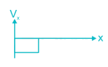
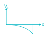
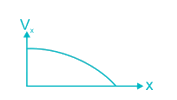
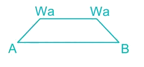
The bending moment diagram for the case shown below in Figure will be: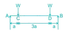
- a)
- b)
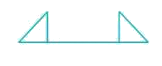
- c)
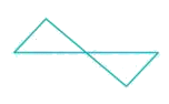
- d)
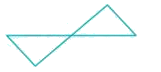
Correct answer is option 'A'. Can you explain this answer?
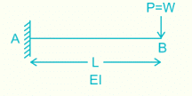
The bending moment diagram for the case shown below in Figure will be:
a)
b)
c)
d)
|
|
Sinjini Nambiar answered |
Here RA = RB = W
Between A to C:
Mx=W×x⇒Ma=0,Mc=WaMx=W×x⇒Ma=0,Mc=Wa
Between C to D:
Mx=W×x−W(x−a)⇒MD=W×4a−W(4a−a)=WaMx=W×x−W(x−a)⇒MD=W×4a−W(4a−a)=Wa
Between D to B:
Mx=W×x−W(x−a)−W(x−4a)⇒MB=W×5a−W(5a−a)−W(5a−4a)=0
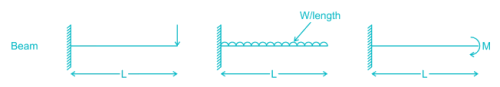
Effective length of a column effectively held in position and restrained in direction at one end but neither held in position nor restrained in direction at the other end is- a)L
- b)0.67 L
- c)0.85 L
- d)2 L
Correct answer is option 'D'. Can you explain this answer?
Effective length of a column effectively held in position and restrained in direction at one end but neither held in position nor restrained in direction at the other end is
a)
L
b)
0.67 L
c)
0.85 L
d)
2 L
|
|
Yash Das answered |
Given condition is “Effective length of a column effectively held in position and restrained in direction at one but neither held in position nor restrained in direction at the other end”
This implies one end fixed, other end free
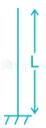
leFF = 2L
Chapter doubts & questions for Strength of Materials (SOM) - SSC JE Mechanical Mock Test Series 2026 2025 is part of Mechanical Engineering exam preparation. The chapters have been prepared according to the Mechanical Engineering exam syllabus. The Chapter doubts & questions, notes, tests & MCQs are made for Mechanical Engineering 2025 Exam. Find important definitions, questions, notes, meanings, examples, exercises, MCQs and online tests here.
Chapter doubts & questions of Strength of Materials (SOM) - SSC JE Mechanical Mock Test Series 2026 in English & Hindi are available as part of Mechanical Engineering exam.
Download more important topics, notes, lectures and mock test series for Mechanical Engineering Exam by signing up for free.
SSC JE Mechanical Mock Test Series 2026
3 videos|1 docs|55 tests
|
|
© EduRev
|
Education Revolution
|


|


Signup to see your scores
go up
within 7 days!
within 7 days!
Takes less than 10 seconds to signup