


All Exams >
Mechanical Engineering >
SSC JE Mechanical Mock Test Series 2026 >
All Questions
All questions of Theory of Machines (TOM) for Mechanical Engineering Exam
In Watt’s Governor, h = ________.- a)Inversely proportional to speed
- b)directly proportional to speed
- c)directly proportional to (speed)2
- d)inversely proportional to (speed)2
Correct answer is option 'D'. Can you explain this answer?
In Watt’s Governor, h = ________.
a)
Inversely proportional to speed
b)
directly proportional to speed
c)
directly proportional to (speed)2
d)
inversely proportional to (speed)2
|
|
Lavanya Menon answered |
For Watt Governor:

i.e height is inversely proportional to (speed)2

For a Hartnell governor, the loads on the spring at the lowest and highest equilibrium speeds are 1150 N and 85 N, respectively. If the lift of the governor is 1.5 cm, then spring stiffness would be - a)700 N/cm
- b)710 N/cm
- c)725 N/cm
- d)690 N/cm
Correct answer is option 'B'. Can you explain this answer?
For a Hartnell governor, the loads on the spring at the lowest and highest equilibrium speeds are 1150 N and 85 N, respectively. If the lift of the governor is 1.5 cm, then spring stiffness would be
a)
700 N/cm
b)
710 N/cm
c)
725 N/cm
d)
690 N/cm
|
|
Avinash Sharma answered |
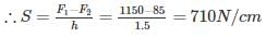
let S be the stiffness of the spring, h be the lift of governor, F1 and F2 are the force exerted on sleeve at lowest and highest equilibrium speed
What will be the locus of a point on a thread unwound from a cylinder?- a)Involute
- b)Helix
- c)Straight line
- d)Circle
Correct answer is option 'A'. Can you explain this answer?
What will be the locus of a point on a thread unwound from a cylinder?
a)
Involute
b)
Helix
c)
Straight line
d)
Circle
|
|
Kritika Joshi answered |
Locus of a Point on a Thread Unwound from a Cylinder
An involute is the curve traced by the end of an imaginary taut string that unwinds itself from a stationary object, such as a cylinder or cone. In this case, we are considering the locus of a point on a thread unwound from a cylinder.
Definition of Involute
An involute is a curve that is traced by a point on a string as the string is unwound from a cylinder. The curve is formed when the string is unwound from the cylinder and the point on the string moves along the surface of the cylinder.
Explanation
As the thread unwinds from the cylinder, the point on the thread moves along the surface of the cylinder. The path traced by the point is an involute. This is because the thread is always tangent to the cylinder at the point where it is unwound. As the thread unwinds, the point moves along the tangent line to the cylinder, forming an involute curve.
The involute curve has several important properties that make it useful in mechanical engineering. For example, it is a self-similar curve, meaning that it can be scaled up or down without changing its shape. This property makes it useful in gear design, where the involute curve is used to design the teeth of gears.
Conclusion
In conclusion, the locus of a point on a thread unwound from a cylinder is an involute. The involute curve is formed when the point on the thread moves along the surface of the cylinder, always tangent to the cylinder at the point where it is unwound. The involute curve has important properties that make it useful in mechanical engineering, particularly in gear design.
If a more stiff spring is used in Hartnell governor, then the governor will be ________.- a)more sensitive
- b)less sensitive
- c)sensitively remains unaffected
- d)isochronous
Correct answer is option 'B'. Can you explain this answer?
If a more stiff spring is used in Hartnell governor, then the governor will be ________.
a)
more sensitive
b)
less sensitive
c)
sensitively remains unaffected
d)
isochronous

|
Abhay Kapoor answered |
A governor is said to be sensitive when it readily responds to a small change of speed.
Stiffness is inversely proportional to sensitiveness. Therefore, if stiffness is greater, the governor will be less sensitive.
A ball and socket joint is example of _______ pair.- a)Screw
- b)Spherical
- c)Turning
- d)Rolling
Correct answer is option 'B'. Can you explain this answer?
A ball and socket joint is example of _______ pair.
a)
Screw
b)
Spherical
c)
Turning
d)
Rolling

|
Bhaskar Joshi answered |
Ball and Socket Joint: An Example of Spherical Pair
A ball and socket joint is a type of mechanical joint that allows for a wide range of motion in multiple directions. It is commonly found in human anatomy, such as in the shoulder and hip joints, and it is also used in various mechanical systems and machines.
Definition and Function:
- A ball and socket joint consists of a ball-shaped end of one component fitting into a cup-shaped socket of another component.
- The ball is free to rotate within the socket, allowing movement in multiple axes, including rotation, flexion, extension, abduction, adduction, and circumduction.
- It provides a high degree of mobility and flexibility, making it suitable for applications where a wide range of motion is required.
Construction and Design:
- The ball and socket joint consists of two main components: a ball and a socket.
- The ball is typically a rounded end or protrusion on one component, while the socket is a concave or spherical cavity on the other component.
- The ball is designed to fit snugly into the socket, allowing for smooth movement and minimizing friction.
- The socket is usually made of a hard material, such as metal or plastic, while the ball may be made of a softer material, such as rubber or synthetic polymers.
- Lubrication is often necessary to reduce friction and wear between the ball and socket surfaces.
Working Principle:
- The ball and socket joint works on the principle of a spherical pair, which allows for rotation and movement in multiple directions.
- The ball acts as a pivot point, enabling the connected components to rotate freely.
- The socket provides stability and support, preventing excessive movement and maintaining the desired range of motion.
- The shape of the ball and socket allows for a wide range of movement, making it suitable for applications where flexibility and mobility are important.
Applications:
- Human anatomy: The ball and socket joints in the human body, such as the shoulder and hip joints, allow for a wide range of motion and are essential for various activities, such as walking, running, and throwing.
- Mechanical systems: Ball and socket joints are used in various mechanical systems and machines, such as robotic arms, prosthetic limbs, automotive suspension systems, and aircraft control systems.
- Furniture: The swivel mechanism in chairs, such as office chairs and bar stools, often uses a ball and socket joint for smooth rotation and movement.
- Sports equipment: Ball and socket joints are commonly found in sports equipment, such as basketballs, soccer balls, and baseballs, where a spherical shape allows for easy rolling and bouncing.
In conclusion, a ball and socket joint is an example of a spherical pair. It allows for a wide range of motion in multiple directions, making it suitable for various applications in both human anatomy and mechanical engineering.
The graph of turning moment diagram is drawn between ________.- a)crank angle and crank radius
- b)crank angle and crank effort
- c)crank effort and crank angle
- d)crank radius and crank angle
Correct answer is option 'C'. Can you explain this answer?
The graph of turning moment diagram is drawn between ________.
a)
crank angle and crank radius
b)
crank angle and crank effort
c)
crank effort and crank angle
d)
crank radius and crank angle
|
|
Sarita Yadav answered |
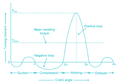
The turning moment diagram also known as crank effort diagram.
- It is the graphical representation of the turning moment or torque or crank effort (X-axis) for various position of crank (Y-axis).
- The area under the turning moment diagram gives the work done per cycle.
- The work done per cycle when divided by the crank angle per cycle gives mean torque Tm.
Which of the following term defines the size of the cam?- a)Base circle
- b)Prime circle
- c)Pitch circle
- d)Pitch curve
Correct answer is option 'A'. Can you explain this answer?
Which of the following term defines the size of the cam?
a)
Base circle
b)
Prime circle
c)
Pitch circle
d)
Pitch curve
|
|
Prateek Mukherjee answered |
Base Circle: It is the smallest circle, drawn tangential to cam profile. The base circle decides the overall size of the cam and thus is fundamental feature.
Pitch Curve: If we hold the cam fixed and rotate the follower in a direction opposite to that of the cam, then the curve generated by the locus of the trace point is called pitch curve. For a knife edge follower, the pitch curve and the cam profile are same whereas for a roller follower, they are separated by the radius of the roller.
Pitch Point: Pitch point corresponds to the point of maximum pressure angle, and a circle drawn with its centre at the cam centre, to pass through the pitch point, is known as the pitch circle.
Prime Circle: It is the smallest circle that can be drawn from the centre of the cam and tangent to the pitch curve.
Which of the following statement is TRUE about the contact ratio?- a)Varies directly to the length of the arc of contact
- b)Inversely proportional to the module
- c)Inversely proportional to the circular pitch
- d)All options are correct
Correct answer is option 'D'. Can you explain this answer?
Which of the following statement is TRUE about the contact ratio?
a)
Varies directly to the length of the arc of contact
b)
Inversely proportional to the module
c)
Inversely proportional to the circular pitch
d)
All options are correct

|
Lakshmi Datta answered |
The ratio of the length of arc of contact to the circular pitch is known as contact ratio i.e. number of pairs of teeth in contact.

Gyroscopic effect is not observed in which of the following actions performed by the ships? - a)Rolling
- b)Pitching
- c)Steering
- d)All of the above
Correct answer is option 'A'. Can you explain this answer?
Gyroscopic effect is not observed in which of the following actions performed by the ships?
a)
Rolling
b)
Pitching
c)
Steering
d)
All of the above
|
|
Diya Sarkar answered |
For the effect of gyroscopic couple to occur, the axis of precession should always be perpendicular to the axis of spin. If, however, the axis of precession becomes parallel to the axis of spin, there will be no effect of the gyroscopic couple acting on the body of the ship.In case of rolling of a ship, the axis of precession (i.e. longitudinal axis) is always parallel to the axis of spin for all positions. Hence, there is no effect of the gyroscopic couple acting on the body of a ship.
Critical or whirling speed is the speed at which the shaft tends to vibrate violently in ________.- a)Transverse direction
- b)Longitudinal direction
- c)Linear direction
- d)None of these
Correct answer is option 'A'. Can you explain this answer?
Critical or whirling speed is the speed at which the shaft tends to vibrate violently in ________.
a)
Transverse direction
b)
Longitudinal direction
c)
Linear direction
d)
None of these
|
|
Partho Choudhary answered |
Whirling speed or Critical speed of a shaft is defined as the speed at which a rotating shaft will tend to vibrate violently in the transverse direction if the shaft rotates in horizontal direction. In other words, the whirling or critical speed is the speed at which resonance occurs.
The number of instantaneous centres of rotation in a slider-crank quick-return mechanism is- a)10
- b)8
- c)6
- d)4
Correct answer is option 'C'. Can you explain this answer?
The number of instantaneous centres of rotation in a slider-crank quick-return mechanism is
a)
10
b)
8
c)
6
d)
4
|
|
Kavya Mehta answered |
Crank and slotted lever quick return motion mechanism is an inversions of Single Slider Crank Chain which is a modification of the basic four bar chain.
Number of instantaneous centres:
where L is number of links.
In case of cam, the maximum value of the pressure angle is kept as-- a)15°
- b)20°
- c)30°
- d)60°
Correct answer is option 'C'. Can you explain this answer?
In case of cam, the maximum value of the pressure angle is kept as-
a)
15°
b)
20°
c)
30°
d)
60°
|
|
Anand Kumar answered |
Pressure Angle is the measure of steepness of the cam profile. The angle between the direction of the follower movement and the normal to the pitch curve at any point is called pressure angle. Pressure angle varies from maximum to minimum during complete rotation.
The pressure should not exceed 30० in case of cams with translating followers (and angle should be less than 45० for low speed cam mechanisms with oscillating followers).
For a vibrating system, if the damping factor is unity, then the system is ________ damped.- a)Under
- b)Over
- c)Critically
- d)Zero
Correct answer is option 'C'. Can you explain this answer?
For a vibrating system, if the damping factor is unity, then the system is ________ damped.
a)
Under
b)
Over
c)
Critically
d)
Zero
|
|
Asha Basu answered |
The damping ratio (ζ = c/cc) is a system parameter, that can vary from un-damped (ζ = 0), under-damped (ζ < 1) through critically damped (ζ = 1) to over-damped (ζ > 1)
Coriolis acceleration component of a slider moving at 75π mm/s on a link rotating at 60 rpm will be- a)600π mm/s2
- b)300π mm/s2
- c)600π2 mm/s2
- d)300π2 mm/s2
Correct answer is option 'D'. Can you explain this answer?
Coriolis acceleration component of a slider moving at 75π mm/s on a link rotating at 60 rpm will be
a)
600π mm/s2
b)
300π mm/s2
c)
600π2 mm/s2
d)
300π2 mm/s2
|
|
Sandeep Sengupta answered |
When a point on one link is sliding along another rotating link, then the Coriolis component of the acceleration is to be calculated.
ac=2ωV

Pick up the wrong statement. A flywheel- a)Is used to limit the inevitable fluctuation of speed during each cycle
- b)Controls the mean speed of rotation
- c)Stores up energy and gives up whenever required
- d)Regulates the speed during one cycle of a prime mover
Correct answer is option 'B'. Can you explain this answer?
Pick up the wrong statement. A flywheel
a)
Is used to limit the inevitable fluctuation of speed during each cycle
b)
Controls the mean speed of rotation
c)
Stores up energy and gives up whenever required
d)
Regulates the speed during one cycle of a prime mover
|
|
Arnav Menon answered |
Explanation:
A flywheel is a mechanical device that is used to store rotational energy. It has a large moment of inertia and is used to smooth out the fluctuations in speed that occur during each cycle of a prime mover. The following are the correct statements regarding flywheel:
• A flywheel is used to limit the inevitable fluctuation of speed during each cycle.
• Stores up energy and gives up whenever required.
• Regulates the speed during one cycle of a prime mover.
• Controls the mean speed of rotation.
The wrong statement is "Controls the mean speed of rotation." This is incorrect because a flywheel does not control the mean speed of rotation, but it helps to maintain a constant speed by increasing the kinetic energy during periods of low speed and releasing it during periods of high speed.
Which of the following mechanisms are examples of force closed kinematic Pairs?A. Cam and roller mechanismB. Door-closing mechanismC. Slider-crank mechanism- a)A and B only
- b)A and C only
- c)B and C only
- d)A, B and C
Correct answer is option 'A'. Can you explain this answer?
Which of the following mechanisms are examples of force closed kinematic Pairs?
A. Cam and roller mechanism
B. Door-closing mechanism
C. Slider-crank mechanism
a)
A and B only
b)
A and C only
c)
B and C only
d)
A, B and C
|
|
Nishanth Basu answered |
Self-closed pair:
When the two elements of a pair are connected together mechanically. The contact between the two can be broken only by destruction of at least one of the members.
All lower pairs and some higher pairs are closed pairs. Sliding pairs, turning pairs, spherical pairs and screw pairs are also closed pairs.
Forced-closed pair:
When two links of a pair are in contact either due to force of gravity or some spring action. In this, the links are not held together mechanically e.g. cam and follower pair (because spring is used to keep the motion constrained).
Slider-crank mechanism does not require such force.
________ gear train is used to connect minute hand to hour hand, in a clock mechanism.- a)Simple
- b)Reverted
- c)Epicyclic
- d)Compound
Correct answer is option 'B'. Can you explain this answer?
________ gear train is used to connect minute hand to hour hand, in a clock mechanism.
a)
Simple
b)
Reverted
c)
Epicyclic
d)
Compound
|
|
Dhruv Dasgupta answered |
Reverted Gear Train in Clock Mechanism
A clock mechanism consists of various gears that are interlinked to perform the function of displaying time accurately. One of the important gear trains used in a clock mechanism is the reverted gear train. Let's understand what it is and how it is used in a clock mechanism.
What is a Reverted Gear Train?
A reverted gear train is a type of gear train that consists of three gears - two idler gears and one driver gear. The driver gear and the idler gears are mounted on the same shaft, and the other end of each idler gear meshes with an output gear. The direction of rotation of the output gear is opposite to that of the driver gear.
How is it Used in a Clock Mechanism?
In a clock mechanism, the reverted gear train is used to connect the minute hand to the hour hand. The minute hand is mounted on the output gear of the reverted gear train, while the hour hand is mounted on the driver gear. As the hour hand rotates, it drives the driver gear of the reverted gear train. The two idler gears mounted on the same shaft as the driver gear, mesh with the output gear. As a result, the output gear rotates in the opposite direction to that of the driver gear. The minute hand mounted on the output gear rotates at a slower speed than the hour hand, thus indicating the minutes that have passed since the last hour.
Advantages of Reverted Gear Train in Clock Mechanism
- Provides a simple and reliable way to connect the minute hand to the hour hand
- Reduces the number of gears required in the clock mechanism
- Increases the accuracy of time display by eliminating errors due to backlash and friction
Conclusion
The reverted gear train is an important gear train used in a clock mechanism to connect the minute hand to the hour hand. It provides a simple and reliable way to display time accurately and efficiently.
________ mechanism produces mathematically an exact straight line motion.- a)Ackermann
- b)Peaucellier‘s
- c)Watt
- d)None of these
Correct answer is option 'B'. Can you explain this answer?
________ mechanism produces mathematically an exact straight line motion.
a)
Ackermann
b)
Peaucellier‘s
c)
Watt
d)
None of these
|
|
Ayush Chawla answered |
Exact Straight-Line Motion Mechanisms Made up of Turning Pairs: Peaucellier mechanism, Hart’s mechanism
Exact Straight-Line Motion Consisting of One Sliding Pair: Scott Russell’s Mechanism
Approximate Straight-Line Motion Mechanisms: Watt’s mechanism, Modified Scott-Russel mechanism, Grasshopper mechanism, Roberts mechanism
The Interference or undercutting in involute gears can be avoided by:-- a)varying the centre distance by changing pressure angle
- b)using modified involute or composite system
- c)increasing the addendum of small wheel and reducing it for the larger wheel
- d)All options are correct
Correct answer is option 'D'. Can you explain this answer?
The Interference or undercutting in involute gears can be avoided by:-
a)
varying the centre distance by changing pressure angle
b)
using modified involute or composite system
c)
increasing the addendum of small wheel and reducing it for the larger wheel
d)
All options are correct
|
|
Ayush Chawla answered |
Methods of elimination of Gear tooth Interference:
- Use of a larger pressure angle (having a larger pressure angle results in a smaller base circle. As a result, more of the tooth profiles become involute)
- Under-cutting of tooth (A portion of teeth below the base circle is cut off. When teeth are produced by this process, the tip of one tooth of a gear will not contact the non-involute portion of the tooth of other gear)
- Tooth stubbing (In this process a portion of the tip of the teeth is removed, thus preventing that portion of the tip of tooth in contacting the non-involute portion of the other meshing tooth).
- Increasing the number of teeth on the gear can also eliminate the chances of interference.
- Increasing slightly the center distance between the meshing gears would also eliminate interference.
- Tooth profile modification or profile shifting (Using profile shifted gears (gears with non-standard profile) can also be an option to eliminate interference. In profile shifted meshing gears, the addendum on the pinion is shorter compared with standard gears).
What is the radial distance of a tooth from the pitch circle to the top of the tooth known as?- a)Dedendum
- b)Addendum
- c)Pitch circle diameter
- d)Module
Correct answer is option 'B'. Can you explain this answer?
What is the radial distance of a tooth from the pitch circle to the top of the tooth known as?
a)
Dedendum
b)
Addendum
c)
Pitch circle diameter
d)
Module
|
|
Stuti Mishra answered |
Addendum: It is the radial distance of a tooth from the pitch circle to the top of the tooth.
Dedendum: It is the radial distance of a tooth from the pitch circle to the bottom of the tooth.
Pitch circle: It is an imaginary circle which by pure rolling action, would give the same motion as the actual gear.
Pitch circle diameter: It is the diameter of the pitch circle. The size of the gear is usually specified by the pitch circle diameter. It is also called as pitch diameter.
Module: It is the ratio of the pitch circle diameter in millimetres to the number of teeth.
Module, m = D / T
What is the condition of complete balancing of reciprocating parts of an engine?- a)Primary force and couple as well as secondary force and couple polygons must close
- b)Primary and secondary couple polygons must close
- c)Primary and secondary force polygons must close
- d)Primary force and secondary couple polygons must close
Correct answer is option 'A'. Can you explain this answer?
What is the condition of complete balancing of reciprocating parts of an engine?
a)
Primary force and couple as well as secondary force and couple polygons must close
b)
Primary and secondary couple polygons must close
c)
Primary and secondary force polygons must close
d)
Primary force and secondary couple polygons must close
|
|
Keerthana Joshi answered |
Conditions of complete balancing of reciprocating parts of an engine:
- Primary forces must balance i.e., primary force polygon is enclosed.
- Primary couples must balance i.e., primary couple polygon is enclosed.
- Secondary forces must balance i.e., secondary force polygon is enclosed.
- Secondary couples must balance i.e., secondary couple polygon is enclosed.
The mass of flywheel of a steam engine is 3250 kg with the radius of gyration of 1 m. The starting torque of the engine is 4500 N - m. What is the angular acceleration (rad/s2) of the flywheel?- a)3.4
- b)2
- c)2.48
- d)1.38
Correct answer is option 'D'. Can you explain this answer?
The mass of flywheel of a steam engine is 3250 kg with the radius of gyration of 1 m. The starting torque of the engine is 4500 N - m. What is the angular acceleration (rad/s2) of the flywheel?
a)
3.4
b)
2
c)
2.48
d)
1.38
|
|
Anu Deshpande answered |
Mass moment of inertia of the flywheel:
I = mk2 = 3250 × 12 = 3250 kg-m2
Starting torque of the engine: T = I.α
Angular acceleration of the flywheel:
α = T/I = 4500/3250 = 18/13 = 1.38 rad/s2
Governor is stable, when the:- a)Radius of rotation of balls increases as the equilibrium speed decreases
- b)Radius of rotation of balls increases as the equilibrium speed increased
- c)Radius of rotation of balls decreases as the equilibrium speed increases
- d)None of these
Correct answer is option 'B'. Can you explain this answer?
Governor is stable, when the:
a)
Radius of rotation of balls increases as the equilibrium speed decreases
b)
Radius of rotation of balls increases as the equilibrium speed increased
c)
Radius of rotation of balls decreases as the equilibrium speed increases
d)
None of these
|
|
Akshara Rane answered |
A governor is said to be stable when for every speed within the working range there is a definite configuration i.e. there is only one radius of rotation of the governor balls at which the governor is in equilibrium. For a stable governor, if the equilibrium speed increases, the radius of governor balls must also increase. A governor is said to be unstable, if the radius of rotation decreases as the speed increases.
A cam in which the follower reciprocates or oscillates in a plane parallel to the axis of the cam is known as- a)Cylindrical Cam
- b)Circular cam
- c)Reciprocating cam
- d)Tangent cam
Correct answer is option 'A'. Can you explain this answer?
A cam in which the follower reciprocates or oscillates in a plane parallel to the axis of the cam is known as
a)
Cylindrical Cam
b)
Circular cam
c)
Reciprocating cam
d)
Tangent cam
|
|
Athul Kumar answered |
Cylindrical Cam
A cylindrical cam is a type of cam mechanism in which the follower reciprocates or oscillates in a plane parallel to the axis of the cam. It consists of a cylindrical-shaped cam with a follower that moves in a straight line or oscillates back and forth within the same plane. This type of cam is commonly used in various mechanical systems and machines.
Working Principle
The working principle of a cylindrical cam involves the rotation of the camshaft, which causes the follower to move in a linear or oscillating motion. The shape of the cam profile determines the type of motion generated by the follower. The follower is in contact with the cam surface, and as the cam rotates, it imparts a motion to the follower.
Advantages
- Simple design: Cylindrical cams have a relatively simple design compared to other types of cams, making them easy to manufacture and maintain.
- Parallel motion: The follower in a cylindrical cam reciprocates or oscillates in a plane parallel to the axis of the cam, which is beneficial in certain applications where this type of motion is required.
- Compact size: Cylindrical cams can be designed with a compact size, making them suitable for applications with limited space.
Applications
Cylindrical cams are widely used in various mechanical systems and machines, including:
- Printing presses: Cylindrical cams are used in printing presses to control the movement of the printing plate and paper feed mechanism.
- Machine tools: Cylindrical cams are used in machine tools to control the movement of the cutting tool or workpiece.
- Packaging machinery: Cylindrical cams are used in packaging machinery to control the movement of the packaging material and sealing mechanisms.
- Textile machinery: Cylindrical cams are used in textile machinery to control the movement of the yarn or fabric during weaving or knitting operations.
In conclusion, a cylindrical cam is a type of cam mechanism in which the follower reciprocates or oscillates in a plane parallel to the axis of the cam. It offers advantages such as a simple design, parallel motion, and compact size. It finds applications in various industries, including printing, machine tools, packaging, and textiles.
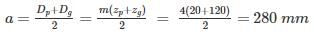
A gear set consists of a 16-tooth pinion driving a 40-tooth gear. The module is 12 mm. The addendum and dedendum are 12 mm and 15 mm, respectively and the gears are cut using 20° pressure angle. The centre distance is- a)36 mm
- b)136 mm
- c)236 mm
- d)336 mm
Correct answer is option 'D'. Can you explain this answer?
A gear set consists of a 16-tooth pinion driving a 40-tooth gear. The module is 12 mm. The addendum and dedendum are 12 mm and 15 mm, respectively and the gears are cut using 20° pressure angle. The centre distance is
a)
36 mm
b)
136 mm
c)
236 mm
d)
336 mm

|
Isha Bajaj answered |
° pressure angle. Determine the pitch diameter, outside diameter, and root diameter of both gears.
In gears, interference takes place when _____.- a)Tip of a tooth of a mating gear digs into the portion between base and root circles
- b)Gears do not move smoothly in the absence of lubrication
- c)Pitch of the gear is not same
- d)Gear teeth are undercut
Correct answer is option 'A'. Can you explain this answer?
In gears, interference takes place when _____.
a)
Tip of a tooth of a mating gear digs into the portion between base and root circles
b)
Gears do not move smoothly in the absence of lubrication
c)
Pitch of the gear is not same
d)
Gear teeth are undercut
|
|
Nandita Chakraborty answered |
Interference in Gears
Interference in gears refers to a specific condition where the tip of a tooth of a mating gear digs into the portion between the base and root circles. This phenomenon occurs when the gears are not properly designed or manufactured, resulting in undesirable contact between the gear teeth. Interference can have negative effects on the performance and durability of gears, and it is important to understand its causes and consequences.
Causes of Interference
Several factors can contribute to the occurrence of interference in gears:
- Inaccurate Gear Design: Interference can be caused by an inaccurate gear design, where the pitch of the gear is not properly calculated or the tooth profile is not correctly defined. This can lead to overlapping of the gear teeth and subsequent interference.
- Improper Gear Manufacturing: Interference can also arise due to errors in the manufacturing process. If the gear tooth dimensions are not accurately produced or if there are deviations from the intended design, interference can occur.
- Undercutting: Undercutting is a condition where the gear teeth are not fully formed, resulting in a concave shape near the root of the tooth. This can contribute to interference as the mating gear tooth can dig into the undercut portion.
Consequences of Interference
Interference in gears can have several negative consequences:
- Noise and Vibration: Interference can lead to noise and vibration during gear operation. The contact between the gear teeth can result in increased friction and impact forces, leading to a noisy and unstable gear system.
- Poor Gear Performance: Interference can affect the overall performance of the gears. It can result in reduced efficiency, power transmission losses, and decreased load-carrying capacity. This can limit the gear system's ability to transmit torque effectively.
- Increased Wear and Failure: Interference can cause accelerated wear of the gear teeth due to increased contact stresses. It can also lead to premature failure of the gears, as the excessive forces and stresses can cause tooth breakage or pitting.
Preventing Interference
To prevent interference in gear systems, it is important to ensure proper gear design and manufacturing:
- Accurate Gear Design: The gear geometry, including the pitch, tooth profile, and clearance, should be accurately calculated and defined to avoid interference. Computer-aided design (CAD) software can be used to simulate and analyze the gear meshing for interference-free operation.
- Precision Gear Manufacturing: High-precision manufacturing processes should be employed to produce gears with accurate tooth dimensions and profiles. This includes proper machining, heat treatment, and finishing operations to eliminate errors and deviations.
- Proper Gear Tooth Profile: The gear tooth profile should be carefully designed to avoid undercutting. This can be achieved by adjusting the tooth geometry and ensuring sufficient clearance between the mating gears.
By addressing these factors, interference in gears can be minimized or eliminated, resulting in improved gear performance, reduced noise, and increased gear system durability.
Transmissibility is defined as- a)Ratio of force applied to the force transmitted to the foundation
- b)Ratio of force transmitted to the foundation to the input force
- c)Sum of the forces applied and the force transmitted to the foundation
- d)Difference of force applied vis-a-vis the force transmitted to the foundation
Correct answer is option 'B'. Can you explain this answer?
Transmissibility is defined as
a)
Ratio of force applied to the force transmitted to the foundation
b)
Ratio of force transmitted to the foundation to the input force
c)
Sum of the forces applied and the force transmitted to the foundation
d)
Difference of force applied vis-a-vis the force transmitted to the foundation
|
|
Siddharth Menon answered |
Transmissibility is defined as the ratio of force transmitted to the foundation to the input force.
Transmissibility is an important concept in mechanical engineering that helps us understand the efficiency of force transmission from a source to a foundation. It is commonly used in the analysis and design of various mechanical systems, such as vibration isolation systems, to ensure that the forces applied are effectively transmitted without unnecessary losses.
Explanation:
Transmissibility is defined as the ratio of the force transmitted to the foundation to the input force. In other words, it quantifies how much force is actually transmitted to the foundation compared to the force applied to the system.
To better understand this concept, let's consider a simple example of a vibration isolation system. In such a system, the input force may be generated by a vibrating machine, and the goal is to minimize the transmission of vibrations to the foundation or surrounding structures.
When the input force is applied to the system, some of it gets transmitted to the foundation, and the rest may be dissipated or absorbed by the system itself. The transmissibility of the system tells us how efficient it is in transmitting the force to the foundation.
Mathematically, transmissibility is expressed as:
Transmissibility = Force Transmitted to Foundation / Input Force
For example, let's say we have an input force of 1000 N applied to a vibration isolation system. After analyzing the system, we find that only 800 N of force is transmitted to the foundation. In this case, the transmissibility would be 800 N / 1000 N = 0.8.
A transmissibility value of less than 1 indicates that there is some loss or attenuation of force during transmission. This loss can be due to various factors such as damping, flexibility, or resonance within the system. On the other hand, a transmissibility value of 1 would mean that all of the input force is effectively transmitted to the foundation.
Importance of Transmissibility:
Transmissibility is an important parameter in mechanical engineering because it helps in designing and optimizing systems for efficient force transmission. By understanding the transmissibility of a system, engineers can make informed decisions about the design parameters such as stiffness, damping, or isolation elements to achieve the desired level of force transmission.
In practical applications, such as isolating vibrations from sensitive equipment or reducing the impact of seismic forces on structures, it is crucial to have a low transmissibility value. This ensures that the majority of the force is effectively transmitted to the foundation, minimizing the potential damage or disruption caused by vibrations or external forces.
In conclusion, transmissibility is defined as the ratio of force transmitted to the foundation to the input force. It is an important concept in mechanical engineering that helps in designing and optimizing systems for efficient force transmission. By understanding and analyzing the transmissibility of a system, engineers can make informed decisions to achieve desired levels of force transmission and minimize potential damage or disruption.
Angle of dwell of cam is defined as the angle- a)During which of the follower returns to its initial position
- b)Of rotation of the cam for definite displacement of the follower
- c)Through which the cam rotates during the period in which the follower remains in the highest position
- d)Moved by the cam from the instant the follower begins to rise, till it reaches its highest position
Correct answer is option 'C'. Can you explain this answer?
Angle of dwell of cam is defined as the angle
a)
During which of the follower returns to its initial position
b)
Of rotation of the cam for definite displacement of the follower
c)
Through which the cam rotates during the period in which the follower remains in the highest position
d)
Moved by the cam from the instant the follower begins to rise, till it reaches its highest position
|
|
Nilanjan Chawla answered |
Angle of Dwell: It is the angle through which the cam turns while the follower remains stationary at the highest or the lowest position.
Which one of the following laws is not applicable for a simple pendulum?- a)the time period does not depend on its magnitude
- b)the time period is proportional to its length
- c)the time period is proportional to square root of its length
- d)the time period is inversely proportional to square root of its acceleration due to gravity
Correct answer is option 'B'. Can you explain this answer?
Which one of the following laws is not applicable for a simple pendulum?
a)
the time period does not depend on its magnitude
b)
the time period is proportional to its length
c)
the time period is proportional to square root of its length
d)
the time period is inversely proportional to square root of its acceleration due to gravity
|
|
Shreya Choudhury answered |
The correct answer is option 'B': the time period is not proportional to the length of a simple pendulum.
Explanation:
A simple pendulum is a mass (called the bob) attached to a string or rod of negligible mass, which is fixed at a pivot point. When the bob is displaced from its equilibrium position and released, it oscillates back and forth.
The time period of a simple pendulum is the time taken for one complete oscillation, i.e., the time taken for the bob to move from one extreme position to the other and back again.
The laws applicable to a simple pendulum are:
1. The time period does not depend on its magnitude:
The time period of a simple pendulum does not depend on the magnitude of the displacement or the mass of the bob. This means that regardless of how far the bob is displaced or the mass of the bob, the time taken for one complete oscillation remains constant.
2. The time period is proportional to the square root of its length:
The time period of a simple pendulum is directly proportional to the square root of its length. This means that if the length of the pendulum is increased, the time period also increases, and vice versa.
3. The time period is inversely proportional to the square root of its acceleration due to gravity:
The time period of a simple pendulum is inversely proportional to the square root of the acceleration due to gravity. This means that if the acceleration due to gravity is increased, the time period decreases, and vice versa.
4. The time period is not proportional to its length:
This is the law that is not applicable to a simple pendulum. The time period of a simple pendulum is not directly proportional to its length. Instead, it is proportional to the square root of its length.
So, from the given options, option 'B' is the correct answer as the time period is not directly proportional to the length of a simple pendulum.
When one of the links of a kinematic chain is fixed, then the chain is called _______.- a)Machine
- b)Mechanism
- c)Structure
- d)Inversion
Correct answer is option 'B'. Can you explain this answer?
When one of the links of a kinematic chain is fixed, then the chain is called _______.
a)
Machine
b)
Mechanism
c)
Structure
d)
Inversion
|
|
Sanskriti Chakraborty answered |
When one of the links of a kinematic chain is fixed, the chain is known as mechanism. It may be used for transmitting or transforming motion. A mechanism with four links is known as simple mechanism, and the mechanism with more than four links is known as compound mechanism. Simplest possible mechanism is four bar chains consisting of four links, each of them forms a turning pair.
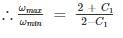
If C1 is the coefficient of speed fluctuation of a flywheel then the ratio of  will be
- a)

- b)

- c)

- d)

Correct answer is option 'D'. Can you explain this answer?
If C1 is the coefficient of speed fluctuation of a flywheel then the ratio of will be
will bea)
b)
c)
d)
|
|
Sinjini Bose answered |
We know that coefficient of fluctuation of speed (C1) is
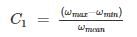
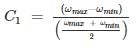
Or, C1 ωmax + C1 ωmin = 2ωmax – 2ωmin
A crank of radius 15 cm is rotating at 50 rpm with an angular acceleration of 60 rad/sec2. The tangential acceleration of the crank is about- a)9 m/s2
- b)8 m/s2
- c)9.5 m/s2
- d)10.5 m/s2
Correct answer is option 'A'. Can you explain this answer?
A crank of radius 15 cm is rotating at 50 rpm with an angular acceleration of 60 rad/sec2. The tangential acceleration of the crank is about
a)
9 m/s2
b)
8 m/s2
c)
9.5 m/s2
d)
10.5 m/s2
|
|
Yash Das answered |
Tangential Acceleration at = rα
α = Angular acceleration = 60 rad/s2
r = radius of crank = 15 cm
∴ at = rα = 60 × 0.15 = 9 m/s
A very soft whisper may have noise level of- a)About 10 db
- b)About 30 db
- c)About 40 db
- d)About 100 db
Correct answer is option 'B'. Can you explain this answer?
A very soft whisper may have noise level of
a)
About 10 db
b)
About 30 db
c)
About 40 db
d)
About 100 db
|
|
Sai Reddy answered |
Some examples of different sound intensities as expressed in dB:
- 180 dB: Rocket at take-off
- 140 dB: Jet engine at take-off
- 120 dB: Rock band
- 110 dB: Loud thunder
- 90 dB: City traffic
- 80 dB: Loud radio
- 60 dB: Ordinary conversation
- 30 dB: Soft whisper
- 0 dB: Softest sound a person can hear
The given kinematic link is
- a)Singular link
- b)Binary link
- c)Ternary link
- d)Quaternary link
Correct answer is option 'C'. Can you explain this answer?
The given kinematic link is
a)
Singular link
b)
Binary link
c)
Ternary link
d)
Quaternary link
|
|
Pallabi Tiwari answered |
A link is defined as a member or a combination of members of a mechanism, connecting other members and having motion relative to them. Thus, a link may consist of one or more resistant bodies.
Links can be classified into binary, ternary and quaternary depending upon their ends.


Elliptical gear train used in differential gear of automobile helps in:- a)Reducing jerk
- b)Assisting in speed change
- c)Reducing speed
- d)Turning
Correct answer is option 'D'. Can you explain this answer?
Elliptical gear train used in differential gear of automobile helps in:
a)
Reducing jerk
b)
Assisting in speed change
c)
Reducing speed
d)
Turning
|
|
Priyanka Tiwari answered |
When a vehicle takes a turn, its other rear wheel covers a greater distance than inner rear wheel. Hence differential gears are used so that both the rear wheel can rotate at different speed. This is achieved with the help of elliptical gear train.
The kinetic energy of a flywheel, having moment of inertia I and angular speed ‘ω’, is given by- a)Iω
- b)Iω2
- c)

- d)None of these
Correct answer is option 'C'. Can you explain this answer?
The kinetic energy of a flywheel, having moment of inertia I and angular speed ‘ω’, is given by
a)
Iω
b)
Iω2
c)
d)
None of these
|
|
Hiral Jain answered |
Kinetic energy of the flywheel is given by:
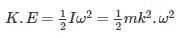
I is mass moment of inertia of the flywheel about its axis of rotation in kg-m2 = m.k2
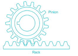
Rack and pinion arrangement is used for:- a)Linear motion to rotary motion
- b)Rotary motion to rotary motion
- c)Linear to linear motion
- d)Rotary to linear motion
Correct answer is option 'D'. Can you explain this answer?
Rack and pinion arrangement is used for:
a)
Linear motion to rotary motion
b)
Rotary motion to rotary motion
c)
Linear to linear motion
d)
Rotary to linear motion
|
|
Prerna Kaur answered |
Rack and pinion gears are used to convert rotation into linear motion. The ‘pinion’ is the normal round gear and the ‘rack’ is straight or flat.
A perfect example of this is the steering system on many cars.
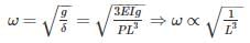
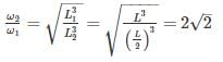
A cantilever beam of cross section area ‘A’, moment of Inertia I and length ‘L’ is having natural frequency ω1. If the beam is accidentally broken into two halves, the natural frequency of the remaining cantilever beam ω2will be such that - a)ω2 < ω1
- b)ω2 > ω1
- c)ω2 = ω1
- d)Cannot be obtained from the given data
Correct answer is option 'B'. Can you explain this answer?
A cantilever beam of cross section area ‘A’, moment of Inertia I and length ‘L’ is having natural frequency ω1. If the beam is accidentally broken into two halves, the natural frequency of the remaining cantilever beam ω2will be such that
a)
ω2 < ω1
b)
ω2 > ω1
c)
ω2 = ω1
d)
Cannot be obtained from the given data
|
|
Anisha Chakraborty answered |

For cantilever beam


Chapter doubts & questions for Theory of Machines (TOM) - SSC JE Mechanical Mock Test Series 2026 2025 is part of Mechanical Engineering exam preparation. The chapters have been prepared according to the Mechanical Engineering exam syllabus. The Chapter doubts & questions, notes, tests & MCQs are made for Mechanical Engineering 2025 Exam. Find important definitions, questions, notes, meanings, examples, exercises, MCQs and online tests here.
Chapter doubts & questions of Theory of Machines (TOM) - SSC JE Mechanical Mock Test Series 2026 in English & Hindi are available as part of Mechanical Engineering exam.
Download more important topics, notes, lectures and mock test series for Mechanical Engineering Exam by signing up for free.
SSC JE Mechanical Mock Test Series 2026
3 videos|1 docs|55 tests
|
|
© EduRev
|
Education Revolution
|


|


Signup to see your scores
go up
within 7 days!
within 7 days!
Takes less than 10 seconds to signup