


All Exams >
Electrical Engineering (EE) >
Electrical Machines for Electrical Engg. >
All Questions
All questions of Synchronous Machines for Electrical Engineering (EE) Exam
The maximum power developed in a synchronous motor occurs at a coupling angle of- a)30°
- b)60°
- c)90°
- d)180°
Correct answer is option 'C'. Can you explain this answer?
The maximum power developed in a synchronous motor occurs at a coupling angle of
a)
30°
b)
60°
c)
90°
d)
180°
|
|
Arshiya Basu answered |
The maximum power developed in a synchronous motor occurs at a coupling angle of 90 degrees.

In which of the following motors the stator and rotor magnetic field rotate at the same speed ?- a)Universal motor
- b)Synchronous motor
- c)Induction motor
- d)Reluctance motor
Correct answer is option 'B'. Can you explain this answer?
In which of the following motors the stator and rotor magnetic field rotate at the same speed ?
a)
Universal motor
b)
Synchronous motor
c)
Induction motor
d)
Reluctance motor
|
|
Sushant Mehta answered |
Synchronous Motor
A synchronous motor is a type of AC motor where the stator and rotor magnetic fields rotate at the same speed. This means that the rotor turns at a constant speed that is synchronized with the frequency of the AC power supply. The synchronous motor is widely used in industrial applications where constant speed is required.
Working Principle
The synchronous motor consists of a stator and a rotor. The stator has a set of coils that produce a rotating magnetic field when AC voltage is applied. The rotor has a set of permanent magnets or electromagnets that produce a magnetic field. When the stator magnetic field rotates, it induces a magnetic field in the rotor. The rotor magnetic field tries to align with the stator magnetic field and starts to rotate at the same speed.
Advantages
- The synchronous motor operates at a constant speed, which makes it suitable for applications where constant speed is required.
- It has a high power factor, which means that it consumes less reactive power from the power supply.
- It has a high efficiency, which means that it converts more electrical energy into mechanical energy.
Disadvantages
- The synchronous motor is more expensive than other types of motors.
- It requires a separate DC power supply to excite the rotor magnetic field.
- It is not self-starting and requires external means to bring it up to synchronous speed.
Applications
- The synchronous motor is used in industrial applications where constant speed is required, such as synchronous generators, compressors, pumps, and fans.
- It is used in power plants to drive large alternators that produce electricity.
- It is used in electric clocks and timers.
In a synchronous motor, the breakdown torque is- a)directly proportional to applied voltage
- b)directly proportional to the square of the applied voltage
- c)inversely proportional to applied voltage
- d)none of the above
Correct answer is option 'A'. Can you explain this answer?
In a synchronous motor, the breakdown torque is
a)
directly proportional to applied voltage
b)
directly proportional to the square of the applied voltage
c)
inversely proportional to applied voltage
d)
none of the above
|
|
Yashvi Shah answered |
Breakdown Torque in Synchronous Motor
Synchronous motors are AC motors that operate at a fixed speed. The speed of the synchronous motor is determined by the frequency of the power supply and the number of poles in the motor. The motor's rotor rotates at the same speed as the rotating magnetic field of the stator. The synchronous motor is used in applications where a constant speed is required, such as in electric clocks, timing devices, and power factor correction.
The breakdown torque is the maximum torque that a motor can produce before it stalls or stops rotating. It is an important parameter in the design of motors and their applications. The breakdown torque of a synchronous motor depends on the applied voltage.
Direct Proportionality to Applied Voltage
The breakdown torque of a synchronous motor is directly proportional to the applied voltage. This means that if the applied voltage is increased, the breakdown torque will also increase. This relationship can be expressed mathematically as:
Tb ∝ V
Where Tb is the breakdown torque and V is the applied voltage.
This relationship is due to the fact that the magnetic field strength in the motor is proportional to the applied voltage. The magnetic field strength determines the torque that the motor can produce.
Conclusion
In conclusion, the breakdown torque of a synchronous motor is directly proportional to the applied voltage. This relationship is due to the fact that the magnetic field strength in the motor is proportional to the applied voltage. The breakdown torque is an important parameter in the design of motors and their applications.
Due to which of the following reasons a synchronous motor fails to pull into synchronism after applying D.C. field current?- a)High field current
- b)Low short circuit ratio
- c)High core losses
- d)Low field current
Correct answer is option 'D'. Can you explain this answer?
Due to which of the following reasons a synchronous motor fails to pull into synchronism after applying D.C. field current?
a)
High field current
b)
Low short circuit ratio
c)
High core losses
d)
Low field current
|
|
Gitanjali Deshpande answered |
Reasons for failure of synchronous motor to pull into synchronism
There can be several reasons for a synchronous motor to fail to pull into synchronism after applying D.C. field current. However, the correct reason among the given options is low field current.
Explanation
Synchronous motor operates at synchronous speed, which is determined by the supply frequency and the number of poles of the motor. In order to achieve this synchronous speed, the rotor of the motor must rotate at the same speed as the rotating magnetic field produced by the stator. For this purpose, the motor must be first brought into synchronism.
The process of bringing the rotor of the synchronous motor into synchronism with the rotating magnetic field produced by the stator is known as synchronization. This is achieved by adjusting the D.C. field current of the motor.
However, if the field current is too low, the magnetic field produced by the rotor will be weak, and as a result, the rotor will not be able to lock into the rotating magnetic field of the stator. This will cause the motor to fail to pull into synchronism.
Therefore, low field current is the reason for the failure of a synchronous motor to pull into synchronism after applying D.C. field current.
Other reasons that can cause the failure of synchronous motor to pull into synchronism are:
- High field current: High field current can cause magnetic saturation, which can lead to instability of the motor and failure to pull into synchronism.
- Low short circuit ratio: Low short circuit ratio can cause the motor to have low torque, which can prevent it from pulling into synchronism.
- High core losses: High core losses can cause the motor to have low efficiency, which can prevent it from pulling into synchronism.
The driving power from the prime-mover driving the alternator is lost but the alternator remains connected to the supply network; the field supply also remains on. The alternator will- a)get burnt
- b)behave as an induction motor but will rotate in the opposite direction
- c)behave as a synchronous motor and will rotate in the same direction
- d)behave as a synchronous motor but will rotate in a reverse direction to that corresponding to generator action
Correct answer is option 'C'. Can you explain this answer?
The driving power from the prime-mover driving the alternator is lost but the alternator remains connected to the supply network; the field supply also remains on. The alternator will
a)
get burnt
b)
behave as an induction motor but will rotate in the opposite direction
c)
behave as a synchronous motor and will rotate in the same direction
d)
behave as a synchronous motor but will rotate in a reverse direction to that corresponding to generator action
|
|
Debanshi Nair answered |
When the driving power from the prime-mover driving the alternator is lost, but the alternator remains connected to the supply network and the field supply remains on, the alternator will behave as a synchronous motor and rotate in the same direction as it would during generator action.
Here is a detailed explanation of why the correct answer is option 'C':
1. Alternator Operation:
An alternator is a synchronous generator that converts mechanical energy into electrical energy. It consists of a rotating magnetic field (created by the rotor or field winding) and a stationary armature winding. When the alternator is driven by a prime-mover (such as a turbine or an engine), it generates electrical power.
2. Prime-Mover Failure:
If the driving power from the prime-mover is lost, the mechanical energy required to rotate the alternator is no longer supplied. As a result, the alternator's rotor will gradually slow down and eventually come to a stop.
3. Connection to the Supply Network:
However, if the alternator remains connected to the supply network, the armature winding will still receive electrical power from the network. This power will create a magnetic field in the stator windings.
4. Field Supply:
In addition, the field supply to the rotor winding remains on. The field winding creates a rotating magnetic field. The direction of this rotating field is determined by the design of the alternator.
5. Synchronous Motor Operation:
In this scenario, the stationary armature winding acts as the stator and the rotating magnetic field (created by the field winding) acts as the rotor. When the armature winding receives electrical power from the supply network, it interacts with the rotating magnetic field and generates a torque.
6. Same Direction Rotation:
Since the rotating magnetic field from the field winding and the electrical power from the supply network are in sync, the alternator will behave as a synchronous motor and rotate in the same direction as it would during generator action.
7. Reverse Direction:
The given options do not indicate that the alternator will rotate in a reverse direction to that corresponding to generator action. Hence, option 'D' is incorrect.
In conclusion, when the driving power is lost but the alternator remains connected to the supply network and the field supply remains on, the alternator will behave as a synchronous motor and rotate in the same direction as it would during generator action.
Two identical synchronous machines A and B running at same speed are connected to each other through an inductor. Machine A is supplying an active power to Machine B and Machine B is supplying reactive power to Machine A, then which among the following is correct?- a)|Va| > |Vb|
- b)|Va| < |Vb|
- c)|Va| = |Vb|
- d)None of the above
Correct answer is option 'B'. Can you explain this answer?
Two identical synchronous machines A and B running at same speed are connected to each other through an inductor. Machine A is supplying an active power to Machine B and Machine B is supplying reactive power to Machine A, then which among the following is correct?
a)
|Va| > |Vb|
b)
|Va| < |Vb|
c)
|Va| = |Vb|
d)
None of the above

|
Crack Gate answered |
Concept:
Active power is directly proportional to the load angle i.e. P ∝ δ
Reactive power is directly proportional to the voltage ∝ V
Application:
Machine A is supplying an active power to Machine B i.e.
⇒ δA > δB
Machine B is supplying reactive power to Machine A
⇒ |Va| < |Vb|
In a 3-phase, 4-pole, 50 Hz synchronous motor, the frequency, pole number and load torque all are halved. The motor speed will be- a)3000 r.p.m.
- b)1500 r.p.m.
- c)750 r.p.m
- d)none of the above
Correct answer is option 'B'. Can you explain this answer?
In a 3-phase, 4-pole, 50 Hz synchronous motor, the frequency, pole number and load torque all are halved. The motor speed will be
a)
3000 r.p.m.
b)
1500 r.p.m.
c)
750 r.p.m
d)
none of the above
|
|
Isha Singh answered |
Explanation:
- The synchronous speed of a synchronous motor is given by the formula: Ns = (120 * f) / P, where Ns is synchronous speed in rpm, f is frequency of AC supply in Hz, and P is the number of poles.
- Given values: frequency is halved (25 Hz), pole number is halved (2), and load torque is halved (reduces the slip).
- Using the formula, we get: Ns = (120 * 25) / 2 = 1500 rpm.
- Therefore, the motor speed will be 1500 rpm.
Which of the following is NOT a condition to be satisfied for the synchronisation of an alternator?- a)Rating of the alternator must be the same as other alternators
- b)Phase of the alternator must be identical with the phase of busbar voltage
- c)Terminal voltage of the alternator must be same as busbar voltage
- d)Frequency of the alternator must be same as busbar voltage
Correct answer is option 'A'. Can you explain this answer?
Which of the following is NOT a condition to be satisfied for the synchronisation of an alternator?
a)
Rating of the alternator must be the same as other alternators
b)
Phase of the alternator must be identical with the phase of busbar voltage
c)
Terminal voltage of the alternator must be same as busbar voltage
d)
Frequency of the alternator must be same as busbar voltage
|
|
Jatin Mukherjee answered |
Introduction:
Synchronizing an alternator with a busbar is an essential step in connecting the alternator to a power system. It ensures that the alternator operates in synchronization with the rest of the system, maintaining a stable and reliable power supply. There are certain conditions that need to be satisfied for successful synchronization.
Condition for Synchronization:
When synchronizing an alternator with a busbar, the following conditions must be satisfied:
1. Phase Synchronization:
The phase of the alternator must be identical to the phase of the busbar voltage. This means that both the alternator and the busbar must have the same phase angle at the time of synchronization. If there is a phase difference, it can cause severe circulating currents and damage to the alternator and the power system.
2. Frequency Synchronization:
The frequency of the alternator must be the same as the busbar voltage. The alternator must generate power at the same frequency as the power system to ensure a smooth transfer of power. If there is a frequency difference, it can lead to instability and fluctuations in the power system.
3. Voltage Synchronization:
The terminal voltage of the alternator must be the same as the busbar voltage. This ensures that the voltage levels are matched, and there are no voltage imbalances during synchronization. If there is a voltage difference, it can result in excessive reactive power flow and affect the stability of the system.
4. Speed Synchronization:
The speed of the alternator must be close to the synchronous speed. Synchronous speed is the speed at which the rotating magnetic field of the alternator rotates. If the alternator speed is significantly different from the synchronous speed, it can cause torque and mechanical stresses on the system.
Explanation of the Correct Answer:
The correct answer is option A - "Rating of the alternator must be the same as other alternators." This condition is not necessary for synchronization. The rating of the alternator refers to its power capacity or the amount of power it can generate. While it is important to consider the rating when connecting multiple alternators to the power system, it is not a direct condition for synchronization. Synchronization mainly focuses on the phase, frequency, voltage, and speed of the alternator.
Conclusion:
Synchronizing an alternator with a busbar requires meeting specific conditions related to phase, frequency, voltage, and speed. While the rating of the alternator is important for overall power system design, it is not directly related to the synchronization process.
Before an alternator can be connected to an infinite bus, which of the following must be the same for the alternator and the infinite bus?- a)Only frequency
- b)Voltage, frequency and phase sequence; and the phase difference between the alternator and infinite voltages must be zero
- c)Only voltage
- d)Only phase sequence
Correct answer is option 'B'. Can you explain this answer?
Before an alternator can be connected to an infinite bus, which of the following must be the same for the alternator and the infinite bus?
a)
Only frequency
b)
Voltage, frequency and phase sequence; and the phase difference between the alternator and infinite voltages must be zero
c)
Only voltage
d)
Only phase sequence
|
|
Crack Gate answered |
Necessary condition for parallel operation of two alternators:
- The phase sequence of the busbar voltages and the incoming machine voltage must be the same
- The busbar voltages and the incoming machine terminal voltage must be in phase.
- The terminal voltage of the incoming machine and the alternator which is to be connected in parallel or with the Busbar voltage should be equal.
- The frequency of the generated voltage of the incoming machine and the frequency of the voltage of the busbar should be equal.
- The phase difference between the alternator and infinite voltages must be zero.
Synchroscope is used to check _________.- a)Frequency difference
- b)Phase angle difference.
- c)Phase sequence
- d)e.c. Phase sequence
Correct answer is option 'A'. Can you explain this answer?
Synchroscope is used to check _________.
a)
Frequency difference
b)
Phase angle difference.
c)
Phase sequence
d)
e.c. Phase sequence

|
Engineers Adda answered |
Concept:
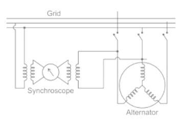
- Synchroscopes are instruments that show the relative frequency (speed) difference and the phase angle between the machine to be synchronized and the system voltage.
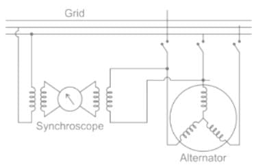
- The synchroscope works based on AC motor in principle. It has two poles connected across any two phases (say red and yellow) of the incoming machine. The armature windings are supplied from the similar two phases (red and yellow) in the switch board bus - bars.
- Synchronization of alternator means connecting an alternator into the grid in parallel with many other alternators, that is in a live system of constant voltage and constant frequency.
- Before connecting an alternator into the grid, the following conditions must be satisfied:
- Equal voltage: The terminal voltage of incoming alternator must be equal to the bus-bar voltage.
- Same frequency: The frequency of generated voltage must be equal to the frequency of the bus-bar voltage.
- Phase sequence: The phase sequence of the three phases of alternator must be similar to that of the grid or busbars. Phase angle: The phase angle between the generated voltage and the voltage of the grid must be zero.
- The first condition of voltage equality can be satisfied by a voltmeter. To satisfy the conditions of equal frequency and identical phases, one of the following two methods can be used: Synchronization using incandescent lamp Synchronization using synchroscope
An alternator of 300 kW is driven by a prime mover of speed regulation of 4% and another alternator of 200 kW is driven by a prime mover of speed regulation of 3%, when operating in parallel, the total load they can take without any of them being overloaded is -- a)425 kW
- b)567 kW
- c)500 kW
- d)257 kW
Correct answer is option 'A'. Can you explain this answer?
An alternator of 300 kW is driven by a prime mover of speed regulation of 4% and another alternator of 200 kW is driven by a prime mover of speed regulation of 3%, when operating in parallel, the total load they can take without any of them being overloaded is -
a)
425 kW
b)
567 kW
c)
500 kW
d)
257 kW
|
|
Engineers Adda answered |
Concept:
The speed regulation of the alternator is given by:

where, SR = Speed regulation
NNL = No-load speed
NFL = Full load speed
Calculation:
Given, P1 = 300 kW
P2 = 200 kW
Let the load shared by two machines be x and y kW.

8x = 9y
Machine 2 produces less power than 1, so it will work at its rated condition.
8x = 9 × 200
x = 225 kW
P1 + P2 = 225 + 200
PT = 425 kW
A change in the excitation of an alternator running in parallel with another alternator:- a)affects its kW output , kVA output and power factor
- b)affects its kVA output and power factor, but not its kW output
- c)affects its kW output and kVA output, but not its power factor
- d)affects its kW output and power factor, but not its kVA output
Correct answer is option 'B'. Can you explain this answer?
A change in the excitation of an alternator running in parallel with another alternator:
a)
affects its kW output , kVA output and power factor
b)
affects its kVA output and power factor, but not its kW output
c)
affects its kW output and kVA output, but not its power factor
d)
affects its kW output and power factor, but not its kVA output
|
|
Crack Gate answered |
Effect of Change in Excitation of Alternator:
- A change in the excitation of an alternator running in parallel with others affects only its KVA output it does not affect the KW output.
- A change in the excitation, thus, affects only the power factor of its output.
Explanation:
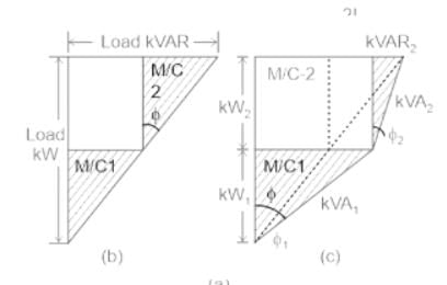
- Let the initial operating conditions of the two parallel alternators be identical i.e. each alternator supplies equal kW and kVAr of load, thus the operating power factors being equal to the load power factor.
- Now, let the excitation of alternator No. 1 be increased so that excitation emf of alternator 1 (E1) becomes greater than E2.
- The difference between the two EMFs sets up a circulating current (IC)
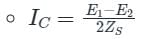
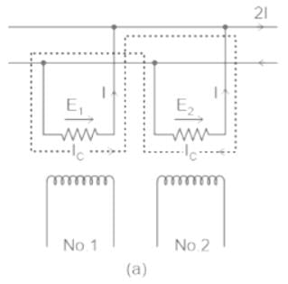
- As seen, IC is vectorially added to the load current of alternator No. 1 and subtracted from that of No. 2.
- The two machines now deliver load currents I1 and I2 at respective power factors of cos φ1 and cos φ2.
- These changes in load currents lead to changes in power factors, such that cos φ1 is reduced, whereas cos φ2 is increased.
- However, the effect on the kW loading of the two alternators is negligible, but kVAR1 supplied by alternator No. 1 is increased, whereas kVAR2 supplied by alternator No. 2 is correspondingly decreased, as shown by the kVA triangles.
Which of the following statements related to parallel operating alternators is correct?- a)Low effciency
- b)Operating in less full load
- c)Operating cost is reduced
- d)Generating cost is increased
Correct answer is option 'C'. Can you explain this answer?
Which of the following statements related to parallel operating alternators is correct?
a)
Low effciency
b)
Operating in less full load
c)
Operating cost is reduced
d)
Generating cost is increased
|
|
Engineers Adda answered |
Advantages of Parallel Operating Alternators:
- When there is maintenance or an inspection, one machine can be taken out from service and the other alternators can keep up with the continuity of supply.
- Load supply can be increased.
- During light loads, more than one alternator can be shut down while the other will operate in a nearly full load.
- High efficiency.
- The operating cost is reduced.
- Ensures the protection of supply and enables cost-effective generation.
- The generation cost is reduced.
- Breaking down of a generator does not cause any interruption in the supply.
- Reliability of the whole power system increases.
When the rotor speed, in a synchronous machine, becomes more than the synchronous speed during hunting, the damper bars develop- a)inductor motor torque
- b)induction generator torque
- c)synchronous motor torque
- d)d.c. motor toque
Correct answer is option 'B'. Can you explain this answer?
When the rotor speed, in a synchronous machine, becomes more than the synchronous speed during hunting, the damper bars develop
a)
inductor motor torque
b)
induction generator torque
c)
synchronous motor torque
d)
d.c. motor toque
|
|
Rithika Pillai answered |
Synchronous machines are designed to operate at a fixed speed known as synchronous speed. However, during hunting, the rotor speed may deviate from the synchronous speed due to sudden variations in load or disturbances in the power system. When the rotor speed becomes more than the synchronous speed during hunting, damper bars develop induction generator torque.
Explanation:
Induction generator torque is the torque developed by the damper bars of the rotor of a synchronous machine when it operates above synchronous speed. The damper bars are short-circuited copper or aluminum bars that are placed in the slots of the rotor laminations. The purpose of the damper bars is to provide damping to the rotor oscillations during hunting.
When the rotor speed is more than the synchronous speed, the relative velocity between the magnetic field and the damper bars increases. This results in the development of eddy currents in the damper bars, which in turn produces a magnetic field that opposes the field of the stator. The interaction between the magnetic fields of the stator and the rotor produces a torque known as induction generator torque.
Induction generator torque is a transient torque that is produced during hunting and is not available during normal operation. The magnitude of the induction generator torque depends on the speed deviation, the damper winding resistance, and the geometry of the damper bars.
In conclusion, when the rotor speed becomes more than the synchronous speed during hunting, the damper bars develop induction generator torque. This torque helps to bring the rotor speed back to the synchronous speed and stabilize the machine.
The angle between the rotating stator flux and rotor poles is called _____ angle.- a)torque
- b)obtuse
- c)synchronizing
- d)power factor
Correct answer is option 'A'. Can you explain this answer?
The angle between the rotating stator flux and rotor poles is called _____ angle.
a)
torque
b)
obtuse
c)
synchronizing
d)
power factor
|
|
Shanaya Mehta answered |
Angle between Rotating Stator Flux and Rotor Poles
The angle between the rotating stator flux and rotor poles is an important concept in electrical engineering, especially in the study of electric motors. This angle is known as the torque angle or power factor angle, and it is a measure of the phase difference between the stator and rotor magnetic fields.
Definition of Torque Angle
The torque angle is defined as the angle between the stator magnetic field and the rotor magnetic field. It is also known as the power factor angle because it is related to the power factor of the motor. The torque angle is an important parameter in the design and operation of electric motors, as it determines the amount of torque that can be produced by the motor.
Importance of Torque Angle
The torque angle is an important parameter in the design and operation of electric motors for several reasons:
1. Determines Motor Performance: The torque angle determines the performance of the motor, including the amount of torque that can be produced and the efficiency of the motor.
2. Affects Power Factor: The torque angle is related to the power factor of the motor. A high torque angle will result in a low power factor, which can lead to reduced efficiency and increased energy consumption.
3. Determines Starting Torque: The torque angle also determines the starting torque of the motor. A high torque angle will result in a lower starting torque, which can make it more difficult to start the motor.
Conclusion
In conclusion, the angle between the rotating stator flux and rotor poles is an important parameter in the design and operation of electric motors, and is known as the torque angle or power factor angle. It determines the performance, efficiency, and starting torque of the motor, and is a key parameter to consider when designing and operating electric motors.
Which of the following methods is used to start a synchronous motor ?- a)Damper winding
- b)Star-delta starter
- c)Damper winding in conjunction with star-delta starter
- d)Resistance starter in the armature circuit
Correct answer is option 'C'. Can you explain this answer?
Which of the following methods is used to start a synchronous motor ?
a)
Damper winding
b)
Star-delta starter
c)
Damper winding in conjunction with star-delta starter
d)
Resistance starter in the armature circuit
|
|
Palak Verma answered |
Understanding Synchronous Motor Starting Methods
Starting a synchronous motor can be challenging due to its nature of requiring a rotating magnetic field for operation. One effective method combines the use of damper windings and a star-delta starter.
1. Damper Winding
- Purpose: Damper windings are used to provide an initial torque to the motor.
- Functionality: They are designed to create a rotating magnetic field when the motor starts, allowing it to reach synchronous speed.
- Integration: The damper winding helps the motor to pick up speed until it synchronizes with the supply frequency.
2. Star-Delta Starter
- Purpose: This method is employed to reduce the starting current and manage the starting torque.
- Functionality: Initially connects the motor in a star configuration, allowing lower voltage and current during startup. After reaching a certain speed, it switches to a delta configuration for normal operation.
- Benefit: This reduces stress on the motor and power supply during startup.
3. Combination of Both Methods
- Enhanced Performance: By using damper windings alongside a star-delta starter, you achieve a smoother startup.
- Reduced Issues: This combination mitigates the high inrush current and torque problems commonly associated with synchronous motor startups.
- Efficiency: Ensures that the motor can start reliably and reach synchronous speed without excessive electrical or mechanical stress.
Conclusion
In conclusion, option 'C' is correct as the combination of damper windings and a star-delta starter provides an effective solution for starting synchronous motors, ensuring both efficiency and reliability during the startup process.
Stability of a synchronous machine- a)decreases with increase in its excitation
- b)increases with increase in its excitation
- c)remains unaffected with increase in excitation
- d)any of the above
Correct answer is option 'B'. Can you explain this answer?
Stability of a synchronous machine
a)
decreases with increase in its excitation
b)
increases with increase in its excitation
c)
remains unaffected with increase in excitation
d)
any of the above
|
|
Saranya Mishra answered |
Stability of a Synchronous Machine
Synchronous machines are widely used in the electrical power system for various applications. The stability of a synchronous machine refers to its ability to maintain a steady and synchronized operation when subjected to disturbances or variations in operating conditions.
The Impact of Excitation on Stability
The excitation of a synchronous machine refers to the magnetic field produced by the field winding in the rotor. The excitation level is typically controlled by the excitation system, which regulates the direct current (DC) supplied to the field winding.
Influence of Excitation on Stability
The stability of a synchronous machine is affected by its excitation level. Here, we will discuss the influence of excitation on stability.
1. Field Current and Synchronous Reactance: The field current determines the strength of the magnetic field, which affects the synchronous reactance of the machine. The synchronous reactance determines the machine's ability to withstand transient disturbances and maintain synchronization with the power system. Therefore, an increase in excitation, which leads to a higher field current, increases the synchronous reactance and enhances the stability of the machine.
2. Short Circuit Ratio: The short circuit ratio (SCR) is the ratio of the synchronous reactance to the subtransient reactance of the machine. A higher SCR indicates a higher stability margin. Increasing the excitation level increases the synchronous reactance, which leads to a higher SCR and improved stability.
3. Power Angle: The power angle is the angle between the stator voltage and the rotor magnetic field. It determines the active power flow in the machine. Higher excitation levels result in a smaller power angle, reducing the stress on the machine during disturbances and improving stability.
4. Field Saturation: Saturation refers to the point where the increase in the excitation current does not produce a proportional increase in the magnetic field. When a synchronous machine operates in the unsaturated region, increasing the excitation level improves stability. However, in the saturated region, further increasing excitation may have a negligible impact on stability.
Conclusion
Based on the above points, it can be concluded that the stability of a synchronous machine increases with an increase in its excitation. The higher excitation level leads to an increased synchronous reactance, improved short circuit ratio, reduced power angle, and enhanced stability margin. However, it is essential to note that there is a limit to the excitation level beyond which stability may not be significantly affected due to field saturation.
A synchronous motor working at leading power factor can be used as- a)voltage booster
- b)phase advancer
- c)noise generator
- d)mechanical synchronizer
Correct answer is option 'B'. Can you explain this answer?
A synchronous motor working at leading power factor can be used as
a)
voltage booster
b)
phase advancer
c)
noise generator
d)
mechanical synchronizer
|
|
Alok Verma answered |
Introduction:
A synchronous motor is an AC motor that operates at a constant speed determined by the frequency of the power supply. It is often used in applications where precise speed control is required, such as in industrial processes or power generation. One of the unique features of a synchronous motor is its ability to operate at a leading power factor.
Explanation:
A synchronous motor working at a leading power factor can be used as a phase advancer. This means that it can be used to improve the power factor of an electrical system.
What is a power factor?
Power factor is a measure of how effectively electrical power is being used in a system. It is the ratio of real power (in watts) to apparent power (in volt-amperes). A power factor of 1 indicates that all the power being supplied is being used effectively, while a power factor less than 1 indicates that there is reactive power in the system.
Leading power factor:
A leading power factor occurs when the current leads the voltage in an AC circuit. This can happen when the load in the circuit is capacitive in nature. In a capacitive load, the current waveform leads the voltage waveform. When a synchronous motor operates at a leading power factor, it means that it is acting as a capacitive load in the system.
Phase advancer:
A phase advancer is a device that is used to improve the power factor of an electrical system. It introduces a leading power factor to compensate for the lagging power factor caused by inductive loads. In this case, a synchronous motor working at a leading power factor can act as a phase advancer.
Advantages of using a synchronous motor as a phase advancer:
- Improved power factor: By introducing a leading power factor, the synchronous motor helps to correct the lagging power factor caused by inductive loads in the system. This improves the overall power factor of the system, leading to more efficient power utilization.
- Reduced reactive power: The reactive power in the system is reduced, leading to a decrease in the current flowing through the system. This helps to reduce the losses in the system and improve the overall efficiency.
- Voltage regulation: A synchronous motor operating at a leading power factor can also help to regulate the voltage in the system. It can act as a voltage booster, compensating for voltage drops caused by inductive loads.
Conclusion:
In conclusion, a synchronous motor working at a leading power factor can be used as a phase advancer to improve the power factor of an electrical system. It helps to compensate for the lagging power factor caused by inductive loads and improves the overall efficiency of the system. Additionally, it can also act as a voltage booster and provide voltage regulation in the system.
Synchroscope is used to check _________.- a)Frequency difference
- b)Phase angle difference.
- c)Phase sequence
- d)RMS voltage
Correct answer is option 'A'. Can you explain this answer?
Synchroscope is used to check _________.
a)
Frequency difference
b)
Phase angle difference.
c)
Phase sequence
d)
RMS voltage
|
|
Crack Gate answered |
Concept:
- Synchroscopes are instruments that show the relative frequency (speed) difference and the phase angle between the machine to be synchronized and the system voltage.
- The synchroscope works based on AC motor in principle. It has two poles connected across any two phases (say red and yellow) of the incoming machine. The armature windings are supplied from the similar two phases (red and yellow) in the switch board bus - bars.
- Synchronization of alternator means connecting an alternator into the grid in parallel with many other alternators, that is in a live system of constant voltage and constant frequency.
- Before connecting an alternator into the grid, the following conditions must be satisfied:
- Equal voltage: The terminal voltage of incoming alternator must be equal to the bus-bar voltage.
- Same frequency: The frequency of generated voltage must be equal to the frequency of the bus-bar voltage.
- Phase sequence: The phase sequence of the three phases of alternator must be similar to that of the grid or busbars. Phase angle: The phase angle between the generated voltage and the voltage of the grid must be zero.
- The first condition of voltage equality can be satisfied by a voltmeter. To satisfy the conditions of equal frequency and identical phases, one of the following two methods can be used: Synchronization using incandescent lamp Synchronization using synchroscope
The cylindrical rotor type alternators are driven by:- a)Water turbine
- b)Wind mill
- c)Steam turbine
- d)Solar cell
Correct answer is option 'C'. Can you explain this answer?
The cylindrical rotor type alternators are driven by:
a)
Water turbine
b)
Wind mill
c)
Steam turbine
d)
Solar cell
|
|
Crack Gate answered |
In synchronous generators or alternator, generally salient-pole type of rotors is driven by hydro-turbines and cylindrical type rotors are driven by steam turbines
Because cylindrical rotors are used in high speed alternators having speed between 1500 rpm to 3000 rpm and salient pole rotors are used in low speed devices, from 100 rpm to 1500 rpm.
Cylindrical type rotors are used in turbo alternators and these are made up of solid steel forging to get high mechanical stress.
Which of the following motors is non-self starting?- a)D.C. series motor
- b)synchronous motor
- c)Squirrel cage induction motor
- d)Wound round induction motor
Correct answer is option 'B'. Can you explain this answer?
Which of the following motors is non-self starting?
a)
D.C. series motor
b)
synchronous motor
c)
Squirrel cage induction motor
d)
Wound round induction motor
|
|
Debanshi Iyer answered |
Understanding Non-Self Starting Motors
In electrical engineering, it's crucial to identify the characteristics of different motors. Among them, the synchronous motor stands out as a non-self starting motor.
Why is the Synchronous Motor Non-Self Starting?
- **Operating Principle:**
- A synchronous motor operates at synchronous speed, which means it requires an external force to bring it to this speed initially.
- **Rotor Design:**
- The rotor of a synchronous motor is typically designed with either permanent magnets or is wound to produce a magnetic field. It cannot develop torque at standstill, which is essential for starting.
- **Starting Mechanism:**
- To initiate motion, synchronous motors often require an auxiliary starting mechanism, such as:
- A separate starting motor
- A variable frequency drive (VFD)
- **Torque Production:**
- Unlike induction motors that generate starting torque due to slip, synchronous motors need to reach synchronous speed before providing torque, making them reliant on external means for startup.
Comparison with Other Motors
- **D.C. Series Motor:**
- This motor develops high starting torque and can start under load conditions.
- **Squirrel Cage Induction Motor:**
- It is self-starting due to the slip between the rotor and stator magnetic fields.
- **Wound Rotor Induction Motor:**
- Also self-starting, it can provide variable speed and torque.
Conclusion
In summary, the synchronous motor's dependence on external forces for initial movement categorizes it as a non-self starting motor, making it distinct from other motor types that can start independently. Understanding these characteristics is vital for selecting the appropriate motor for various applications.
The speed of a synchronous motor- a)increases as the load increases
- b)decreases as the load decreases
- c)always remains constant
- d)none of the above
Correct answer is option 'C'. Can you explain this answer?
The speed of a synchronous motor
a)
increases as the load increases
b)
decreases as the load decreases
c)
always remains constant
d)
none of the above
|
|
Jyoti Basak answered |
Synchronous motors are a type of AC motor that operates at a constant speed called the synchronous speed. This speed is determined by the frequency of the power supply and the number of poles in the motor. The synchronous speed can be calculated using the formula:
Synchronous Speed = (120 * Frequency) / Number of Poles
Now, let's discuss each option and understand why option 'C' is correct:
a) Increases as the load increases:
If the load on a synchronous motor increases, the motor will start to slow down. This is because the increased load will require more torque to be produced by the motor, and as a result, the motor speed will decrease. However, the synchronous speed of the motor will remain constant regardless of the load. So, this option is incorrect.
b) Decreases as the load decreases:
Similarly, if the load on a synchronous motor decreases, the motor will start to speed up. This is because the reduced load will require less torque to be produced by the motor, and as a result, the motor speed will increase. However, the synchronous speed of the motor will remain constant regardless of the load. So, this option is also incorrect.
c) Always remains constant:
The correct answer is option 'C'. The speed of a synchronous motor always remains constant irrespective of the load. This is because a synchronous motor operates at its synchronous speed, which is determined by the power supply frequency and the number of poles in the motor. The rotor of a synchronous motor rotates at the same speed as the rotating magnetic field produced by the stator, thus ensuring a constant speed.
d) None of the above:
Option 'D' is incorrect as the correct answer is option 'C'.
In summary, the speed of a synchronous motor always remains constant regardless of the load. This is because the motor operates at its synchronous speed, which is determined by the power supply frequency and the number of poles in the motor.
Which of the following losses is not dissipated by the stator core surface in a synchronous motor?- a)Eddy current losses in the conductors
- b)Iron losses in the stator
- c)Copper losses in the slot portion of the conductors
- d)Windage losses
Correct answer is option 'D'. Can you explain this answer?
Which of the following losses is not dissipated by the stator core surface in a synchronous motor?
a)
Eddy current losses in the conductors
b)
Iron losses in the stator
c)
Copper losses in the slot portion of the conductors
d)
Windage losses
|
|
Rajveer Saha answered |
Explanation:
In a synchronous motor, various losses occur which need to be dissipated. The stator core surface plays a role in dissipating some of these losses. However, there is one particular loss that is not dissipated by the stator core surface, which is windage losses.
Eddy Current Losses in the Conductors:
Eddy current losses occur in the conductors of the stator due to the alternating magnetic field produced by the rotor. These losses result from the resistance of the conductors to the flow of current and are dissipated as heat. The stator core surface helps in dissipating these losses.
Iron Losses in the Stator:
Iron losses, also known as core losses, occur in the stator core due to the magnetic field variations. These losses consist of hysteresis losses and eddy current losses in the laminated core. The stator core surface provides a path for the dissipation of these losses.
Copper Losses in the Slot Portion of the Conductors:
Copper losses occur in the stator windings due to the resistance of the conductors. These losses result from the flow of current through the conductors and are dissipated as heat. The stator core surface aids in dissipating these losses.
Windage Losses:
Windage losses occur due to the friction and air resistance experienced by the rotating parts of the synchronous motor, such as the rotor. These losses are not related to the stator core surface and are not dissipated by it. Windage losses are typically dissipated through cooling mechanisms such as fans or ventilation systems.
Conclusion:
In a synchronous motor, the losses dissipated by the stator core surface include eddy current losses in the conductors, iron losses in the stator, and copper losses in the slot portion of the conductors. The loss not dissipated by the stator core surface is windage losses, which are related to the friction and air resistance of the rotating parts.
Which of the following losses, in a synchronous motor, does not vary with load?- a)Windage loss
- b)Copper losses
- c)Any of the above
- d)None of the above
Correct answer is option 'A'. Can you explain this answer?
Which of the following losses, in a synchronous motor, does not vary with load?
a)
Windage loss
b)
Copper losses
c)
Any of the above
d)
None of the above
|
|
Jyoti Basak answered |
Answer:
In a synchronous motor, there are several losses that occur during its operation. These losses include windage losses and copper losses. However, out of these losses, windage loss does not vary with load.
1. Windage Loss:
Windage loss refers to the power loss that occurs due to the mechanical friction between the rotating parts of the motor and the air. It is caused by the movement of air around the rotor and stator. This loss is primarily dependent on the speed of the motor rather than the load. Therefore, windage loss remains constant regardless of the load on the motor.
2. Copper Losses:
Copper losses are the power losses that occur in the motor windings due to the resistance of the copper wires. These losses are caused by the flow of current through the stator and rotor windings. Copper losses are dependent on the square of the current flowing through the windings and therefore vary with the load on the motor. As the load increases, the current in the windings also increases, leading to higher copper losses.
Conclusion:
Based on the above explanation, we can conclude that windage losses do not vary with load in a synchronous motor. This is because windage losses are primarily dependent on the speed of the motor, which remains relatively constant regardless of the load. On the other hand, copper losses vary with the load as they are directly proportional to the square of the current flowing through the windings.
A 3-phase synchronous motor is running clockwise. If the direction of its field current is reversed- a)the motor will stop
- b)the motor continue to run in the same direction
- c)the winding of the motor will burn
- d)the motor will run in the reverse direction
Correct answer is option 'B'. Can you explain this answer?
A 3-phase synchronous motor is running clockwise. If the direction of its field current is reversed
a)
the motor will stop
b)
the motor continue to run in the same direction
c)
the winding of the motor will burn
d)
the motor will run in the reverse direction
|
|
Raghav Nambiar answered |
Explanation:
A 3-phase synchronous motor is a motor that runs on a 3-phase AC supply and has a rotor that rotates at the same speed as the rotating magnetic field produced by the stator winding. The direction of rotation of the motor is determined by the direction of the rotating magnetic field produced by the stator winding.
When the direction of the field current is reversed, the direction of the magnetic field produced by the stator winding also gets reversed. This affects the direction of the rotating magnetic field and hence, the direction of rotation of the motor.
Option B is the correct answer because the motor will continue to run in the same direction, but with a slight decrease in speed. This is because the rotor has some inertia, and it takes some time for the rotor to adjust to the new direction of the rotating magnetic field.
Option A is incorrect because the motor will not stop. The motor will continue to run, but with a slight decrease in speed.
Option C is incorrect because the winding of the motor will not burn. Reversing the direction of the field current does not cause any harm to the windings.
Option D is incorrect because the motor will not run in the reverse direction. The motor will continue to run in the same direction, but with a slight decrease in speed.
Conclusion:
Therefore, the correct answer is option B, i.e., the motor will continue to run in the same direction.
The mechanical displacement of the rotor with respect to the stator, in polyphase multipolar synchronous motors running at full load, is of the order of- a)zero degree
- b)two degrees
- c)five degrees
- d)ten degrees
Correct answer is option 'C'. Can you explain this answer?
The mechanical displacement of the rotor with respect to the stator, in polyphase multipolar synchronous motors running at full load, is of the order of
a)
zero degree
b)
two degrees
c)
five degrees
d)
ten degrees
|
|
Abhay Khanna answered |
Introduction:
In polyphase multipolar synchronous motors running at full load, the mechanical displacement of the rotor with respect to the stator is an important parameter. It determines the position of the rotor relative to the stator and affects the performance of the motor. The correct answer to the given question is option 'C', which states that the mechanical displacement is of the order of five degrees.
Explanation:
To understand why the mechanical displacement is approximately five degrees, let's consider some key points about synchronous motors:
1. Synchronous Motors:
Synchronous motors are AC motors that operate at a fixed speed determined by the frequency of the power supply. The rotor rotates at the same speed as the rotating magnetic field produced by the stator.
2. Stator and Rotor Magnetic Fields:
The stator produces a rotating magnetic field, while the rotor contains permanent magnets or electromagnets. The interaction between the stator and rotor magnetic fields results in the rotation of the rotor.
3. Synchronous Speed:
The synchronous speed (Ns) of a synchronous motor is given by the formula:
Ns = 120f / P
where 'f' is the frequency of the power supply in Hz and 'P' is the number of poles.
4. Slip:
The slip (S) of a synchronous motor is defined as the difference between the synchronous speed and the actual rotor speed, expressed as a percentage of the synchronous speed.
S = (Ns - N) / Ns * 100
where 'N' is the actual rotor speed.
5. Full Load Operation:
When a synchronous motor is running at full load, the slip is very small, approaching zero. This means that the rotor speed is very close to the synchronous speed.
Mechanical Displacement:
In a synchronous motor, the mechanical displacement refers to the angular displacement between the rotor and the stator. It is determined by the number of poles and the slip of the motor.
6. Pole Configuration:
The mechanical displacement depends on the pole configuration of the motor. In a polyphase multipolar synchronous motor, the rotor and stator have multiple poles.
7. Order of Mechanical Displacement:
The order of the mechanical displacement can be calculated using the formula:
Mechanical Displacement = 360 / (P / 2)
where 'P' is the number of poles.
In the given question, the motor is described as a polyphase multipolar synchronous motor running at full load. Since the slip is very small at full load, the rotor speed is close to the synchronous speed. Therefore, the mechanical displacement is primarily determined by the pole configuration.
For a polyphase multipolar synchronous motor, the mechanical displacement is generally in the range of 5 to 15 degrees. Option 'C' states that the mechanical displacement is of the order of five degrees, which is a reasonable estimate for such motors.
Conclusion:
In polyphase multipolar synchronous motors running at full load, the mechanical displacement of the rotor with respect to the stator is approximately five degrees. This displacement is primarily determined by the pole configuration of the motor.
When the stator windings are connected in such a fashion that the number of poles are made half, the speed of the rotor of a synchronous motor- a)remains same as the original value
- b)decreases to half the original value
- c)tends to becomes zero
- d)increases to two times the original value
Correct answer is option 'D'. Can you explain this answer?
When the stator windings are connected in such a fashion that the number of poles are made half, the speed of the rotor of a synchronous motor
a)
remains same as the original value
b)
decreases to half the original value
c)
tends to becomes zero
d)
increases to two times the original value
|
|
Surbhi Chopra answered |
Explanation:
When the stator windings of a synchronous motor are connected in such a way that the number of poles is halved, it is referred to as pole changing. In this case, the synchronous speed of the motor changes. The synchronous speed of a motor is given by the formula:
Synchronous speed = (120 * frequency) / number of poles
Therefore, when the number of poles is halved, the synchronous speed of the motor doubles. This is because the frequency of the power supply remains constant, but the number of poles has decreased, leading to an increase in the synchronous speed.
Now, the actual speed of the rotor of a synchronous motor depends on the load on the motor. If the load on the motor remains constant, the speed of the rotor will also increase to twice its original value. However, if the load on the motor increases, the speed of the rotor will decrease.
Therefore, the correct answer is option 'D' - the speed of the rotor of a synchronous motor increases to two times the original value when the stator windings are connected in such a fashion that the number of poles are made half.
Summary:
- Pole changing in a synchronous motor involves connecting the stator windings in such a way that the number of poles is halved.
- The synchronous speed of the motor doubles when the number of poles is halved.
- The actual speed of the rotor of a synchronous motor depends on the load on the motor.
- If the load on the motor remains constant, the speed of the rotor will increase to twice its original value when the number of poles is halved.
Power factor of a synchronous motor is unity when- a)the armature current is maximum
- b)the armature current is minimum
- c)the armature current is zero
- d)none of the above
Correct answer is option 'B'. Can you explain this answer?
Power factor of a synchronous motor is unity when
a)
the armature current is maximum
b)
the armature current is minimum
c)
the armature current is zero
d)
none of the above
|
|
Mihir Chawla answered |
Explanation:
The power factor of a synchronous motor is defined as the ratio of active power (real power) to the apparent power. It is a measure of how effectively the motor converts electrical power into mechanical power.
Power Factor:
The power factor of a synchronous motor can be leading, lagging, or unity. A leading power factor means the current leads the voltage, a lagging power factor means the current lags the voltage, and a unity power factor means the current is in phase with the voltage.
Armature Current and Power Factor:
The power factor of a synchronous motor is influenced by the armature current. The armature current is the current flowing through the armature winding of the motor. It is responsible for producing the magnetic field that interacts with the stator magnetic field to generate torque.
Unity Power Factor:
A synchronous motor operates at a unity power factor when the armature current is minimum. This is because at minimum armature current, the reactive power component is negligible, and the motor only consumes active power. The power factor is defined as the ratio of active power to apparent power. When the reactive power is zero, the active power and apparent power become equal, resulting in a power factor of unity.
Other Options:
a) When the armature current is maximum, the motor is consuming both active and reactive power. The power factor will be less than unity.
c) When the armature current is zero, the motor is not consuming any power, and the power factor is undefined.
d) None of the above options correctly describe the condition for a unity power factor in a synchronous motor.
Therefore, the correct answer is option 'B' - the armature current is minimum.
The working of a synchronous motor is similar to- a)gear train arrangement
- b)transmission of mechancial power by shaft
- c)distribution transformer
- d)turbine
Correct answer is option 'B'. Can you explain this answer?
The working of a synchronous motor is similar to
a)
gear train arrangement
b)
transmission of mechancial power by shaft
c)
distribution transformer
d)
turbine
|
|
Arpita Banerjee answered |
Working of Synchronous Motor
The synchronous motor is a type of AC motor that operates at a constant speed determined by the frequency of the AC supply. The working of a synchronous motor is similar to the transmission of mechanical power by a shaft.
Stator
The stator of a synchronous motor consists of a three-phase winding that is connected to the AC supply. The stator produces a rotating magnetic field that rotates at the frequency of the AC supply.
Rotor
The rotor of a synchronous motor consists of a set of electromagnets that are arranged in a circular pattern. The rotor is connected to a DC power supply, which produces a magnetic field that interacts with the rotating magnetic field produced by the stator.
Operation
When the AC supply is applied to the stator, it produces a rotating magnetic field. The magnetic field produced by the rotor is also rotating, but at a slightly slower speed than the magnetic field produced by the stator.
As a result, the rotor tries to catch up with the rotating magnetic field produced by the stator. When the rotor catches up with the rotating magnetic field, it locks into place and rotates at the same speed as the stator.
Applications
Synchronous motors are commonly used in applications where a constant speed is required, such as in power plants, paper mills, and chemical plants. They are also used in applications where precise control of speed is required, such as in robotics and CNC machines.
Conclusion
In summary, the working of a synchronous motor is similar to the transmission of mechanical power by a shaft. The stator produces a rotating magnetic field, and the rotor produces a magnetic field that interacts with the rotating magnetic field produced by the stator. When the rotor catches up with the rotating magnetic field, it locks into place and rotates at the same speed as the stator.
Chapter doubts & questions for Synchronous Machines - Electrical Machines for Electrical Engg. 2025 is part of Electrical Engineering (EE) exam preparation. The chapters have been prepared according to the Electrical Engineering (EE) exam syllabus. The Chapter doubts & questions, notes, tests & MCQs are made for Electrical Engineering (EE) 2025 Exam. Find important definitions, questions, notes, meanings, examples, exercises, MCQs and online tests here.
Chapter doubts & questions of Synchronous Machines - Electrical Machines for Electrical Engg. in English & Hindi are available as part of Electrical Engineering (EE) exam.
Download more important topics, notes, lectures and mock test series for Electrical Engineering (EE) Exam by signing up for free.
Electrical Machines for Electrical Engg.
35 videos|85 docs|42 tests
|

Signup to see your scores go up within 7 days!
Study with 1000+ FREE Docs, Videos & Tests
10M+ students study on EduRev
|
© EduRev
|
Education Revolution
|


|


Signup on EduRev and stay on top of your study goals
10M+ students crushing their study goals daily