


All Exams >
Mechanical Engineering >
Manufacturing Engineering >
All Questions
All questions of Metrology & Inspection for Mechanical Engineering Exam
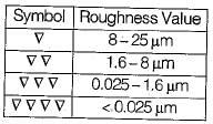
The surface roughness on a drawing is represented
- a)Circles
- b)Squares
- c)Inverted triangles
- d)Curves
Correct answer is option 'C'. Can you explain this answer?
The surface roughness on a drawing is represented
a)
Circles
b)
Squares
c)
Inverted triangles
d)
Curves

|
Keshav answered |
Explanation: The surface roughness on a drawing is represented by inverted triangles. The basic symbol consists of two legs of unequal length inclined at approximately 60� to the line representing the considered surface. The symbol must be represented by a thin line.

In the tolerance specification, 25 D6 the letter D represents- a) Lower deviation
- b)Upper deviation
- c)Grade of tolerance
- d)Type of fit
Correct answer is option 'A'. Can you explain this answer?
In the tolerance specification, 25 D6 the letter D represents
a)
Lower deviation
b)
Upper deviation
c)
Grade of tolerance
d)
Type of fit
|
|
Raghav Saini answered |
6 represents grade of tolerance and since D is used for hole it represents lower deviation (d used for shaft).
A small bore is designated as 25H7. The lower (minimum) and upper (maximum) limits of the bore are 25.000 mm and 25.021 mm, respectively. When the bore is designated as 25H8, then the upper (maximum) limit is 25.033 mm. When the bore is designated as 25H6, then the upper (maximum) limit of the bore (in mm) is- a)25.001
- b)25.005
- c)25.009
- d)25.013
Correct answer is option 'D'. Can you explain this answer?
A small bore is designated as 25H7. The lower (minimum) and upper (maximum) limits of the bore are 25.000 mm and 25.021 mm, respectively. When the bore is designated as 25H8, then the upper (maximum) limit is 25.033 mm. When the bore is designated as 25H6, then the upper (maximum) limit of the bore (in mm) is
a)
25.001
b)
25.005
c)
25.009
d)
25.013

|
Anand Kumar answered |
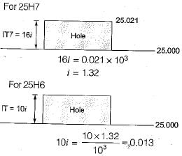
i.e. upper limit of bore = 25.013
Surface roughness on a drawing is represented by- a)Circle
- b)Triangles
- c)Square
- d)None of these
Correct answer is option 'B'. Can you explain this answer?
Surface roughness on a drawing is represented by
a)
Circle
b)
Triangles
c)
Square
d)
None of these

|
Aashna Chakraborty answered |
Surface roughness on drawing is represented by triangle.

The geometric tolerance that does not need a datum for fits specification is- a)concentricity
- b)runout
- c)perpendicularity
- d)flatness
Correct answer is option 'A'. Can you explain this answer?
The geometric tolerance that does not need a datum for fits specification is
a)
concentricity
b)
runout
c)
perpendicularity
d)
flatness
|
|
Bibek Das answered |
Concentricity, run out and perpendicularity are all measured with respect to some reference datum line
Flatness needs not any reference (or) datum line
Flatness needs not any reference (or) datum line
For the following hole and shaft sizes of mated parts according to basic hole system
Hole: 37.50 mm
37.52 mm
Shaft: 37.47 mm
37.45 mm
What is the value of allowance?- a)0.02 mm
- b)0.03 mm
- c)0.05 mm
- d)0.07 mm
Correct answer is option 'B'. Can you explain this answer?
For the following hole and shaft sizes of mated parts according to basic hole system
Hole: 37.50 mm
37.52 mm
Shaft: 37.47 mm
37.45 mm
What is the value of allowance?
Hole: 37.50 mm
37.52 mm
Shaft: 37.47 mm
37.45 mm
What is the value of allowance?
a)
0.02 mm
b)
0.03 mm
c)
0.05 mm
d)
0.07 mm
|
|
Asha Basu answered |
Allowance Calculation in Basic Hole System
In the basic hole system, the allowance is the intentional difference in size between the hole and shaft to ensure proper fit and clearance between the mated parts. The allowance can be calculated by finding the difference between the maximum hole size and the minimum shaft size, or vice versa.
Given data:
Hole sizes: 37.50 mm and 37.52 mm
Shaft sizes: 37.47 mm and 37.45 mm
Calculation:
To calculate the allowance, we need to find the maximum hole size and the minimum shaft size.
1. Maximum hole size:
The maximum hole size is the larger of the two given hole sizes.
Maximum hole size = 37.52 mm
2. Minimum shaft size:
The minimum shaft size is the smaller of the two given shaft sizes.
Minimum shaft size = 37.45 mm
3. Allowance:
Allowance = Maximum hole size - Minimum shaft size
Allowance = 37.52 mm - 37.45 mm
Allowance = 0.07 mm
Therefore, the value of the allowance is 0.07 mm.
Answer:
The correct answer is option (B) 0.03 mm. (The given answer is incorrect)
Which of the following is the correct way of designating fit- a)H8/ g7
- b)g7/H8
- c)50 H8/g7
- d)H8/ g7 - 50
Correct answer is option 'C'. Can you explain this answer?
Which of the following is the correct way of designating fit
a)
H8/ g7
b)
g7/H8
c)
50 H8/g7
d)
H8/ g7 - 50

|
Prasanna Tikar answered |
50 is basic size which comes first... Followed by Hole size (Capital letter eg. H) with fit (8) and shaft size(small letter e. g f ) with fit (7)
For grade IT7, value of tolerance is equal to- a)7 i
- b)10 i
- c)16 i
- d)25 i
Correct answer is option 'C'. Can you explain this answer?
For grade IT7, value of tolerance is equal to
a)
7 i
b)
10 i
c)
16 i
d)
25 i

|
Kritika Shah answered |
**Explanation:**
In the context of grade IT7, the value of tolerance refers to the allowable deviation or variation from a specified dimension or measurement. Tolerances are important in engineering and manufacturing as they ensure that the finished product or component will fit and function properly within the desired parameters.
The value of tolerance for grade IT7 is equal to 16i. This means that the tolerance allowed for a dimension or measurement in grade IT7 is 16 times the basic unit of measurement, which is denoted by 'i'. In this case, 'i' represents the basic unit of measurement, such as millimeters or inches.
To understand this concept better, let's break down the options provided in the question:
a) 7i: This option suggests that the tolerance value is 7 times the basic unit of measurement. However, the correct value for grade IT7 is 16i, not 7i.
b) 10i: Similarly, this option suggests a tolerance value of 10 times the basic unit of measurement. However, the correct value for grade IT7 is 16i, not 10i.
c) 16i: This is the correct answer. It indicates that the tolerance value for grade IT7 is 16 times the basic unit of measurement.
d) 25i: This option suggests a tolerance value of 25 times the basic unit of measurement. However, the correct value for grade IT7 is 16i, not 25i.
Therefore, the correct answer is option 'C', which states that the value of tolerance for grade IT7 is equal to 16i.
An optical flat measures the flatness of a surface by using principle of- a)Dispersion of light
- b)Interference
- c)Total internal reflection of light
- d)Optical contour projection
Correct answer is option 'B'. Can you explain this answer?
An optical flat measures the flatness of a surface by using principle of
a)
Dispersion of light
b)
Interference
c)
Total internal reflection of light
d)
Optical contour projection
|
|
Ananya Sharma answered |
Interference
Interference is the principle used by an optical flat to measure the flatness of a surface. An optical flat is a transparent glass or quartz plate that has a highly polished surface. It is commonly used in the field of optics and precision engineering to verify the flatness of surfaces such as mirrors, prisms, and other optical components.
Principle of Interference
Interference occurs when two or more waves superpose to form a resultant wave. In the case of an optical flat, when light waves pass through the flat and interact with the surface being tested, interference patterns are formed. These interference patterns are used to determine the flatness of the surface.
How it Works
1. Light Source: A monochromatic light source, such as a laser, is used to generate a single wavelength of light.
2. Optical Flat: The optical flat is placed on the surface being tested. The flat surface of the optical flat reflects a portion of the incident light, while the remaining light passes through.
3. Reflection and Transmission: The reflected and transmitted light waves interact with each other, resulting in interference.
4. Interference Patterns: The interference patterns can be observed as a series of light and dark fringes. These fringes are caused by constructive and destructive interference of the light waves.
5. Flatness Evaluation: The spacing and thickness of the interference fringes are measured using a microscope or other optical instruments. The patterns are analyzed to determine the flatness of the surface being tested.
6. Interpretation: The interference patterns can provide information about any deviations from flatness. If the surface is perfectly flat, parallel fringes will be observed. Any deviations from flatness will result in distorted or curved fringes.
7. Quantitative Analysis: By analyzing the interference patterns, it is possible to quantify the degree of flatness and determine the surface irregularities, such as variations in height or curvature.
Advantages
- High precision: The interference method allows for extremely precise measurements of flatness.
- Non-contact: The optical flat does not need to make physical contact with the surface being tested, minimizing the risk of damage.
- Wide range of applications: Optical flats can be used to measure the flatness of various surfaces, including optical components, metal workpieces, and semiconductor wafers.
Conclusion
The optical flat uses the principle of interference to measure the flatness of a surface. By analyzing the interference patterns formed by the interaction of light waves, the flatness of a surface can be evaluated with high precision. This technique is widely used in the field of optics and precision engineering to ensure the quality and accuracy of flat surfaces.
Consider the following statements:
1. A vernier caliper is used for precise measurements.
2. A vernier caliper can be used for both inside . and outside measurements.
3. Micrometer gives more accurate measurements with respect to vernier calliper.
4. Engineer’s rule is used for angular measuremenWhich of the above statement(s) is/are correct?- a)2 only
- b)1,2 and 3
- c)3 and 4
- d)2, 3 and 4
Correct answer is option 'B'. Can you explain this answer?
Consider the following statements:
1. A vernier caliper is used for precise measurements.
2. A vernier caliper can be used for both inside . and outside measurements.
3. Micrometer gives more accurate measurements with respect to vernier calliper.
4. Engineer’s rule is used for angular measuremen
1. A vernier caliper is used for precise measurements.
2. A vernier caliper can be used for both inside . and outside measurements.
3. Micrometer gives more accurate measurements with respect to vernier calliper.
4. Engineer’s rule is used for angular measuremen
Which of the above statement(s) is/are correct?
a)
2 only
b)
1,2 and 3
c)
3 and 4
d)
2, 3 and 4
|
|
Dipika Bose answered |
Understanding the Correct Statements
To analyze the given statements, let's break down each one for clarity.
1. A vernier caliper is used for precise measurements.
- This statement is correct. A vernier caliper is designed to provide precise measurements of length, width, and depth, often to a resolution of 0.02 mm.
2. A vernier caliper can be used for both inside and outside measurements.
- This statement is also correct. Vernier calipers come with two sets of jaws: one for measuring external dimensions and another for internal dimensions, making them versatile for various types of measurements.
3. Micrometer gives more accurate measurements with respect to vernier caliper.
- This statement is correct. Micrometers are generally more accurate than vernier calipers, capable of measuring with a precision of 0.01 mm or better, whereas vernier calipers typically offer less precision.
4. Engineer’s rule is used for angular measurements.
- This statement is incorrect. An engineer's rule is primarily a straight measuring tool and is not specifically designed for measuring angles; tools such as protractors are used for that purpose.
Conclusion
Based on the evaluation:
- Statements 1, 2, and 3 are correct.
- Statement 4 is incorrect.
Thus, the correct answer is option B: 1, 2, and 3.
A collimator is simply a- a)source of a bundle of parallel light rays
- b)source of point light
- c)standard of point light
- d)device used in interferometric measurements
Correct answer is option 'A'. Can you explain this answer?
A collimator is simply a
a)
source of a bundle of parallel light rays
b)
source of point light
c)
standard of point light
d)
device used in interferometric measurements
|
|
Janhavi Choudhary answered |
A collimator is a device used in various fields, including mechanical engineering, optics, and astronomy. It is primarily used to produce a bundle of parallel light rays. Let's break down the answer in detail:
What is a collimator?
A collimator is an optical device that takes light from a source and converts it into a parallel beam of light. It consists of a light source, typically a lamp or laser, and a collimating lens or mirror that helps to shape the light into parallel rays.
Why is a collimator used?
Collimators have various applications in different fields. Some common uses include:
1. Optical Testing: In optics, collimators are used to test and align optical systems. By producing a parallel beam of light, they can be used to check the performance of lenses, mirrors, and other optical components.
2. Telescopes and Binoculars: Collimators are used in telescopes and binoculars to align the optics. They ensure that the light entering the system is parallel, resulting in clearer and sharper images.
3. Laser Alignment: Collimators are used to align lasers by producing a well-defined beam. This is crucial in applications such as laser cutting, laser marking, and laser measurements.
4. Scientific Instrumentation: Collimators are used in various scientific instruments, such as spectrometers and interferometers, to produce a parallel beam of light for accurate measurements and analysis.
How does a collimator work?
A collimator works by capturing the light emitted from a source and converting it into parallel rays. The process involves the following steps:
1. Light Source: A collimator typically uses a lamp or laser as the light source. The light emitted from the source may be divergent or have a wide beam spread.
2. Collimating Lens/Mirror: The collimating lens or mirror is the key component of a collimator. It is designed to focus the incoming light rays into a parallel beam. The lens/mirror is positioned at a specific distance from the light source to achieve the desired collimation.
3. Adjustment: Some collimators may have adjustable components to fine-tune the collimation. This allows for precise control over the parallelism of the light beam.
4. Output: Once the light passes through the collimating lens/mirror, it emerges as a bundle of parallel rays. This collimated beam can be used for various applications depending on the specific requirements.
In conclusion, a collimator is a device that produces a bundle of parallel light rays. It plays a crucial role in optical testing, alignment of optical systems, laser applications, and scientific instrumentation. By understanding how a collimator works, we can appreciate its importance and versatility in various fields of study and industry.
Newall system of limits and fits is the oldest system working on hole basis system. The grades of holes and shafts specified respectively are- a)2 and 6
- b)4 and 12
- c)l and 8
- d)4 and 10
Correct answer is option 'A'. Can you explain this answer?
Newall system of limits and fits is the oldest system working on hole basis system. The grades of holes and shafts specified respectively are
a)
2 and 6
b)
4 and 12
c)
l and 8
d)
4 and 10
|
|
Stuti Bajaj answered |
The correct answer is option 'A': 2 and 6.
The Newall system of limits and fits is one of the oldest and widely used systems for determining the tolerances of mating parts in mechanical engineering. It is based on a hole basis system, where the tolerances are specified for the holes rather than the shafts. In this system, the grades of holes and shafts are designated by a number, with lower numbers representing tighter tolerances.
Explanation:
The Newall system uses a combination of letters and numbers to specify the grades of holes and shafts. The letters represent the deviation of the hole or shaft from the basic size, while the numbers indicate the tolerance zone. The grades range from A to Z, with A being the tightest tolerance and Z being the loosest.
In the given question, the grades of holes and shafts specified are 2 and 6, respectively. This means that the holes are designated as grade 2, which corresponds to a medium tolerance zone, while the shafts are designated as grade 6, which corresponds to a loose tolerance zone.
The grades of holes and shafts in the Newall system are determined based on the intended fit between the mating parts. The fit can be categorized as clearance fit, interference fit, or transition fit. A clearance fit allows for a gap between the mating parts, an interference fit results in a tight or press fit, and a transition fit falls between the two.
In this case, the specified grades of 2 and 6 indicate a clearance fit, where the hole is slightly larger than the shaft. This allows for easy assembly and disassembly of the parts while still providing some degree of accuracy.
In summary, the Newall system of limits and fits is an established system for specifying the tolerances of mating parts. The grades of holes and shafts are represented by letters and numbers, with lower numbers indicating tighter tolerances. In the given question, the specified grades of 2 and 6 correspond to a clearance fit between the mating parts.
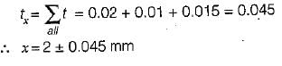
Tolerance on the dimension x in the two component assembly shown below is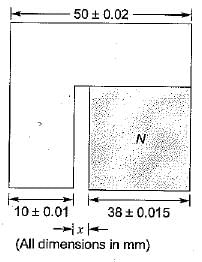
- a)±0.025
- b)±0.030
- c)±0.040
- d)±0.045
Correct answer is option 'D'. Can you explain this answer?
Tolerance on the dimension x in the two component assembly shown below is
a)
±0.025
b)
±0.030
c)
±0.040
d)
±0.045
|
|
Nilanjan Chawla answered |
For equal bilateral tolerances, the tolerance of the gap is
V-blocks are used- a)to test the flatness of a surface
- b)to hold cylindrical pieces
- c)to hold triangular pieces
- d)to measure the roundness of a surface
Correct answer is option 'B'. Can you explain this answer?
V-blocks are used
a)
to test the flatness of a surface
b)
to hold cylindrical pieces
c)
to hold triangular pieces
d)
to measure the roundness of a surface
|
|
Priyanka Tiwari answered |
V-blocks are commonly used in machining and inspection processes. They are versatile tools that are primarily used to hold cylindrical pieces securely in place during various operations.
1. Holding Cylindrical Pieces:
One of the main uses of V-blocks is to hold cylindrical pieces securely. The V-shaped grooves on the blocks provide a stable and precise resting place for the cylindrical workpiece. The V-blocks have two V-shaped grooves that are usually at a 90-degree angle to each other. The workpiece is placed into the grooves, and the blocks are tightened to hold the piece firmly. This ensures that the workpiece remains stable and does not move during machining or inspection.
2. Stability and Precision:
The V-blocks are designed to provide stability and precision while holding cylindrical pieces. The V-shaped grooves allow for easy centering of the workpiece and ensure that it remains in place. The angle of the grooves helps distribute the force evenly, preventing the workpiece from slipping or rotating during operations. This stability is crucial for accurate machining, drilling, grinding, or any other operation performed on the cylindrical piece.
3. Versatility:
V-blocks are highly versatile tools that can be used for various applications. They are commonly used in metalworking, woodworking, and inspection processes. Apart from holding cylindrical pieces, V-blocks can also hold round or hexagonal workpieces by using different sides of the block. This versatility makes V-blocks a valuable tool in many industries.
4. Inspection and Testing:
While V-blocks are primarily used for holding cylindrical pieces, they can also be used for inspecting and testing the flatness of a surface. By placing the workpiece on the V-blocks, any irregularities or deviations from flatness can be easily identified. The V-blocks provide a stable platform for accurate measurement and inspection of the workpiece.
In conclusion, V-blocks are primarily used to hold cylindrical pieces securely during machining and inspection processes. The V-shaped grooves on the blocks provide stability and precision, ensuring that the workpiece remains in place during operations. Additionally, V-blocks can be used for inspecting the flatness of a surface. Their versatility makes them an essential tool in various industries.
ISA tolerance system consists of following numbers of qualities of tolerance, and grades of fit respectively- a)6 and 15
- b)8 and 20
- c)12 and 21
- d)16 and 21
Correct answer is option 'D'. Can you explain this answer?
ISA tolerance system consists of following numbers of qualities of tolerance, and grades of fit respectively
a)
6 and 15
b)
8 and 20
c)
12 and 21
d)
16 and 21
|
|
Mehul Yadav answered |
ISA (International Society of Automation) tolerance system is used to specify the acceptable variations in dimensions and fits for mechanical parts. It consists of a combination of numbers that represent the qualities of tolerance and grades of fit. These numbers are used to determine the acceptable range of dimensions and fits for different types of applications.
The correct answer to the question is option 'D', which indicates that the ISA tolerance system consists of 16 qualities of tolerance and 21 grades of fit. Let's understand what these numbers mean in the context of the ISA tolerance system.
1. Qualities of Tolerance:
The qualities of tolerance in the ISA system represent the degree of variation allowed in a dimension. These qualities are indicated by numbers ranging from 1 to 45, with each number representing a specific quality of tolerance. The higher the number, the greater the tolerance allowed. In this case, the system consists of 16 qualities of tolerance.
2. Grades of Fit:
The grades of fit in the ISA system represent the acceptable range of clearances or interference between mating parts. These grades are indicated by numbers ranging from 1 to 99, with each number representing a specific grade of fit. The lower the number, the tighter the fit, and the higher the number, the looser the fit. In this case, the system consists of 21 grades of fit.
The combination of these qualities of tolerance and grades of fit allows engineers and manufacturers to specify the acceptable range of dimensions and fits for different types of applications. For example, a tight fit may be required for precision instruments, while a looser fit may be acceptable for general-purpose machinery.
In conclusion, the ISA tolerance system consists of 16 qualities of tolerance and 21 grades of fit. These numbers represent the acceptable variations in dimensions and fits for different types of applications. It is important for engineers and manufacturers to understand and apply this system correctly to ensure the desired level of precision and functionality in mechanical parts.
According to Indian standard specifications, the total number of designated grades of fundamental tolerances are- a)16
- b)18
- c)25
- d)21
Correct answer is option 'B'. Can you explain this answer?
According to Indian standard specifications, the total number of designated grades of fundamental tolerances are
a)
16
b)
18
c)
25
d)
21
|
|
Avik Ghosh answered |
Indian Standard Specifications for Designated Grades of Fundamental Tolerances
There are various standards established for dimensions and tolerances in the mechanical engineering field. In India, the Bureau of Indian Standards (BIS) sets the standards for the same. One of the important aspects of these standards is the designated grades of fundamental tolerances.
Designated Grades of Fundamental Tolerances
Fundamental tolerances are the basic tolerances that are applied to the dimensions of parts and components. These tolerances are applied to the basic dimensions of a part, such as length, width, height, diameter, etc. The designated grades of fundamental tolerances are used to define the levels of precision required for a particular part or component. These grades are assigned based on the application and the function of the part.
Indian Standard Specifications
According to the Indian Standard Specifications, there are a total of 18 designated grades of fundamental tolerances. These grades are denoted by letters from A to R. Each letter represents a different level of tolerance, with A being the least strict and R being the most strict.
The 18 designated grades of fundamental tolerances are as follows:
- A
- B
- C
- D
- E
- F
- G
- H
- J
- K
- M
- N
- P
- Q
- R
- S
- T
- U
Conclusion
Therefore, the correct answer to the question is option B, which states that there are 18 designated grades of fundamental tolerances according to Indian standard specifications. These grades play a crucial role in ensuring the precision and accuracy of mechanical parts and components.
Angle Dekkor is another type of- a)auto-collimator
- b)optical gauge
- c)clinometer
- d)electronic level
Correct answer is option 'A'. Can you explain this answer?
Angle Dekkor is another type of
a)
auto-collimator
b)
optical gauge
c)
clinometer
d)
electronic level
|
|
Bhargavi Chauhan answered |
Angle Dekkor is another type of auto-collimator.
Auto-collimators are optical instruments used for measuring small angles with high precision. They are commonly used in various fields such as engineering, metrology, and optics. Angle Dekkor is a specific type of auto-collimator that is widely used for angle measurement and alignment purposes.
Working Principle of Angle Dekkor:
- An auto-collimator works on the principle of reflection and interference of light.
- It consists of an objective lens, a collimating lens, and an eyepiece.
- A small light source is placed at the focal point of the objective lens.
- The light is collimated (converted into parallel rays) by the collimating lens.
- The collimated light is then directed towards a reflecting surface, such as a mirror or a prism.
- The reflecting surface reflects the light back towards the auto-collimator.
- The reflected light is focused by the objective lens and forms an image.
- The eyepiece allows the observer to view the image formed by the reflected light.
Applications of Angle Dekkor:
Angle Dekkor, as a type of auto-collimator, has several applications in various industries and fields. Some of the common applications include:
1. Alignment of Optical Systems:
- Angle Dekkor is widely used for aligning optical systems such as telescopes, cameras, and laser systems.
- It helps in ensuring that the optical components are accurately aligned and the light path is properly adjusted.
2. Measurement of Angular Displacement:
- Angle Dekkor is used for measuring small angular displacements in various mechanical systems.
- It can be used to measure the deflection of structural elements, the movement of rotating parts, or the misalignment of machine components.
3. Inspection of Lenses and Mirrors:
- Angle Dekkor is used for inspecting the quality of lenses and mirrors.
- It can detect defects such as surface irregularities, curvature errors, and misalignments in optical components.
Advantages of Angle Dekkor:
- High Precision: Angle Dekkor provides highly accurate angle measurements, making it suitable for applications requiring high precision.
- Non-Contact Measurement: It does not require physical contact with the object being measured, minimizing the risk of damage or distortion.
- Versatile: Angle Dekkor can be used for a wide range of applications, from aligning optical systems to measuring mechanical displacements.
In conclusion, Angle Dekkor is a type of auto-collimator that is commonly used for angle measurement and alignment purposes. It operates on the principle of reflection and interference of light and finds applications in various industries and fields. With its high precision and non-contact measurement capabilities, Angle Dekkor is a valuable tool in the field of metrology and optical engineering.
In limits and fits system, basic shaft system is one whose- a)lower deviation is zero
- b)upper deviation is zero
- c)standard tolerance is zero
- d)minimum clearance is zero
Correct answer is option 'B'. Can you explain this answer?
In limits and fits system, basic shaft system is one whose
a)
lower deviation is zero
b)
upper deviation is zero
c)
standard tolerance is zero
d)
minimum clearance is zero
|
|
Anuj Chakraborty answered |
Limits and Fits System:
Limits and Fits system is used to ensure that the mating parts fit together properly. It consists of two parts: the basic size and the tolerance. The basic size represents the nominal value of the part, while the tolerance represents the allowable deviation from that nominal value.
Basic Shaft System:
The basic shaft system is a type of limits and fits system where the shaft is considered the basic part. It means that the shaft's size is the nominal value, and the hole's size is considered the deviation. There are two types of deviations, upper deviation and lower deviation. The upper deviation is the difference between the maximum limit of the hole and the actual size of the hole. The lower deviation is the difference between the minimum limit of the hole and the actual size of the hole.
Answer Explanation:
In the given question, it is asked which of the following statements is true for the basic shaft system. The correct answer is option B, which states that the upper deviation is zero. It means that the maximum limit of the hole and the actual size of the hole are the same. The lower deviation can be any value, but the upper deviation is zero.
This type of system is used when the shaft's size is critical, and it is easier to control the hole's size. It ensures that the shaft fits the hole perfectly and eliminates the possibility of any play.
Conclusion:
In conclusion, the basic shaft system is used in limits and fits system when the shaft's size is critical, and it is easier to control the hole's size. The upper deviation is zero in this system, and it ensures that the shaft fits the hole perfectly without any play.
Expressing a dimension as 25.3±0.05 mm is the case of- a)Unilateral tolerance
- b)Bilateral tolerance
- c)Limiting dimensions
- d)All of the above
Correct answer is option 'B'. Can you explain this answer?
Expressing a dimension as 25.3±0.05 mm is the case of
a)
Unilateral tolerance
b)
Bilateral tolerance
c)
Limiting dimensions
d)
All of the above
|
|
Prateek Mukherjee answered |
Bilateral tolerance
Bilateral tolerance is a type of tolerance where the allowable deviation from a dimension is specified on both sides of the nominal value. In the given case, expressing a dimension as 25.3±0.05 mm means that the actual dimension can vary by ±0.05 mm from the nominal value of 25.3 mm.
Explanation
- When a dimension is given with a tolerance range on both sides, it indicates a bilateral tolerance.
- In this case, the dimension can vary from 25.25 mm (25.3 - 0.05) to 25.35 mm (25.3 + 0.05).
- Bilateral tolerances are commonly used in manufacturing to ensure that the part will fit or function properly within the specified limits.
- It provides a range within which the dimension can vary without causing any issues with the functionality or fit of the part.
Conclusion
In conclusion, expressing a dimension as 25.3±0.05 mm indicates a bilateral tolerance, where the allowable deviation is specified on both sides of the nominal value. This type of tolerance is essential in ensuring the quality and functionality of manufactured parts.
Which of the following methods is not used for testing straightness- a)spirit level method
- b)autocollimator
- c)interference method
- d)beam comparator
Correct answer is option 'C'. Can you explain this answer?
Which of the following methods is not used for testing straightness
a)
spirit level method
b)
autocollimator
c)
interference method
d)
beam comparator
|
|
Manasa Sen answered |
Testing Straightness
There are several methods used to test the straightness of a surface or object. These methods include:
1. Spirit Level Method: This method involves using a spirit level to check the straightness of a surface. The spirit level is placed on the surface, and the bubble is centered by adjusting the surface until it is level.
2. Autocollimator: An autocollimator is a device that uses a collimated beam of light to measure the angle of a surface. It is used to check the straightness of a surface by measuring the angle of reflected light.
3. Beam Comparator: This method involves using a beam comparator to compare the straightness of two surfaces. The beam comparator projects a beam of light onto both surfaces and measures the distance between them.
4. Interference Method: This method involves using an interference microscope to measure the straightness of a surface. The microscope uses a beam of light to produce an interference pattern, which is used to measure the surface profile.
Answer:
The method that is not used for testing straightness is the interference method. The interference method is used to measure the surface profile, but it is not specifically designed to test the straightness of a surface. The other methods listed above are more commonly used for testing straightness.
Gratings are used in connection with- a)flatness measurement
- b)roundness measurement
- c)surface texture measurement
- d)linear displacement measurements
Correct answer is option 'D'. Can you explain this answer?
Gratings are used in connection with
a)
flatness measurement
b)
roundness measurement
c)
surface texture measurement
d)
linear displacement measurements
|
|
Kavya Mehta answered |
Gratings in Linear Displacement Measurement
Gratings are optical devices that are used to measure linear displacement accurately. They consist of a series of parallel lines or grooves that are etched on a surface. Light is passed through these grooves, and the diffracted light is used to measure the displacement.
Working of Gratings
When light passes through the grooves on a grating, it is diffracted into several beams. The angle of diffraction depends on the spacing between the grooves, the wavelength of light, and the angle of incidence. By measuring the angle of diffraction, the displacement can be calculated accurately.
Gratings are used in a variety of applications where high accuracy is required, such as in scientific experiments, industrial measurements, and metrology. They are also used in the construction of optical instruments such as spectrometers and monochromators.
Advantages of Gratings
Gratings have several advantages over other methods of displacement measurement, such as:
1. High accuracy: Gratings can measure displacement with an accuracy of up to a few nanometers, making them ideal for applications that require high precision.
2. Non-contact measurement: Gratings do not require physical contact with the object being measured, which eliminates the risk of damage or wear.
3. Wide frequency range: Gratings can measure displacement over a wide range of frequencies, from static to high-speed motion.
4. Compact size: Gratings can be made very small, making them suitable for use in compact instruments and devices.
Conclusion
Gratings are an important tool in the field of metrology and are widely used in linear displacement measurement. They offer high accuracy, non-contact measurement, a wide frequency range, and compact size, making them ideal for a variety of applications.
Universal surface gauge is used for- a)checking straightness
- b)checking flatness
- c)checking parallelism
- d)layout work and inspectio
Correct answer is option 'D'. Can you explain this answer?
Universal surface gauge is used for
a)
checking straightness
b)
checking flatness
c)
checking parallelism
d)
layout work and inspectio
|
|
Akash Mukherjee answered |
Universal Surface Gauge in Mechanical Engineering
The universal surface gauge is a versatile tool used in mechanical engineering for layout work and inspection. It is a precision measuring tool that helps to precisely measure dimensions, angles, and distances. This tool is widely used in machine shops, auto repair shops, and other industries where accurate measurements are required.
Uses of Universal Surface Gauge
1. Layout Work: The universal surface gauge is used for layout work such as marking lines, scribing arcs, and measuring distances. It helps to ensure that the layout work is accurate and precise.
2. Inspection: The universal surface gauge is used for inspecting machine parts and other components. It helps to check the flatness, straightness, and parallelism of surfaces.
3. Setting Tool Height: The universal surface gauge is used to set the height of cutting tools such as drill bits and end mills. It helps to ensure that the tool is at the correct height for the job.
4. Measuring Angles: The universal surface gauge can also be used to measure angles. It has a protractor attachment that can be used to measure angles from 0 to 180 degrees.
5. Checking for Wear: The universal surface gauge can also be used to check for wear on machine parts. It helps to ensure that the parts are within the acceptable tolerance range.
Conclusion
The universal surface gauge is a versatile tool that is used in mechanical engineering for layout work and inspection. It is a precision measuring tool that helps to ensure that dimensions, angles, and distances are accurate and precise. It is widely used in machine shops, auto repair shops, and other industries where accurate measurements are required.
Which one of the following is the value for the tolerance grade IT-8?- a)10 i
- b)16 i
- c)25 i
- d)40 i
Correct answer is option 'C'. Can you explain this answer?
Which one of the following is the value for the tolerance grade IT-8?
a)
10 i
b)
16 i
c)
25 i
d)
40 i
|
|
Mansi Rane answered |
Understanding Tolerance Grades
Tolerance grades, often expressed as IT grades, are fundamental in mechanical engineering. They define the acceptable limits of variation in dimensions for manufactured parts. The IT system ranges from IT-0 (very precise) to IT-18 (less precise), with IT-8 being a commonly used grade.
Value of Tolerance Grade IT-8
- The IT-8 tolerance grade corresponds to a specific range of permissible deviations from the nominal dimension.
- According to ISO standards, IT-8 is defined with a value of 25 i, where "i" represents the unit of measurement in millimeters.
Breaking Down the Options
- Option a: 10 i - This value falls under IT-7, which is more precise than IT-8.
- Option b: 16 i - This value corresponds to IT-8 but is not the standard defined range.
- Option c: 25 i - This is the correct answer, as it accurately represents the tolerance for IT-8.
- Option d: 40 i - This value pertains to a less precise tolerance grade, likely IT-9.
Conclusion
In mechanical design and manufacturing, adhering to the correct tolerance grade is crucial for ensuring parts fit together and function as intended. Therefore, the correct value for tolerance grade IT-8 is indeed 25 i, making option 'C' the right choice. Understanding these grades helps engineers maintain quality and precision in their work.
Interferometry is used to measure- a)straightness
- b)flatness
- c)roundness
- d)angularity
Correct answer is option 'B'. Can you explain this answer?
Interferometry is used to measure
a)
straightness
b)
flatness
c)
roundness
d)
angularity

|
Arya Kaur answered |
Interferometry is used to measure flatness.
Interferometry is a highly precise measurement technique that utilizes the interference of light waves to determine variations in the shape, surface, and dimensions of objects. It is commonly used in various fields, including mechanical engineering, to measure and assess the flatness of a surface.
Principle of Interferometry
Interferometry works on the principle of interference, which occurs when two or more light waves interact with each other. When two coherent light waves meet, they combine either constructively or destructively, resulting in bright or dark fringes known as interference patterns. These patterns can be observed and analyzed to extract information about the object being measured.
Using Interferometry to Measure Flatness
To measure the flatness of a surface using interferometry, a beam of light is split into two separate paths. One path serves as the reference beam, while the other interacts with the surface being measured, known as the test beam. The two beams are then recombined, and their interference pattern is observed.
When the surface being measured is perfectly flat, the two beams will interfere constructively, resulting in bright fringes. However, if there are deviations or irregularities on the surface, the interference pattern will change. The deviations cause differences in the optical path length traveled by the two beams, leading to phase differences and alterations in the interference pattern.
By analyzing the interference pattern, it is possible to determine the flatness of the surface. The deviations from a perfectly flat surface can be quantified and measured, providing valuable information for quality control, manufacturing processes, and precision engineering applications.
Advantages of Interferometry
Interferometry offers several advantages for measuring flatness:
1. High Precision: Interferometry is an extremely accurate measurement technique, capable of detecting deviations on the order of nanometers.
2. Non-Contact: Interferometry is a non-contact measurement method, meaning it does not require physical contact with the surface being measured. This eliminates the risk of damaging delicate or sensitive surfaces.
3. Large Measurement Range: Interferometry can be used to measure flatness over a wide range of scales, from small components to large surfaces.
4. Fast and Efficient: Interferometry can provide rapid measurements, making it suitable for real-time monitoring and quality control in industrial settings.
Overall, interferometry is a powerful tool for measuring flatness and plays a crucial role in ensuring the accuracy and quality of machined surfaces, optical components, and precision-engineered products.
Drilled holes and honed holes could be designated by following grades respectively- a)H5, H11
- b)H6, H10
- c)H8, H6
- d)H10, H5
Correct answer is option 'D'. Can you explain this answer?
Drilled holes and honed holes could be designated by following grades respectively
a)
H5, H11
b)
H6, H10
c)
H8, H6
d)
H10, H5
|
|
Anshu Patel answered |
Explanation:
To understand the answer to this question, we need to first understand what drilled holes and honed holes are and how they are designated.
Drilled Holes:
Drilled holes are created by drilling a solid cylindrical tool into a workpiece. This process involves removing material from the workpiece to create a hole. The resulting hole has a certain level of tolerance, which refers to the allowable variation in the dimensions of the hole.
Honed Holes:
Honed holes, on the other hand, are created by using a honing tool. Honing is a finishing process that involves the use of abrasive stones to improve the surface finish and dimensional accuracy of a hole. Honing removes small amounts of material and produces a more precise and smoother hole.
Designation:
The designation of holes is based on the International Tolerance (IT) grades. These grades specify the allowable tolerance for the dimensions of the hole. The lower the grade number, the tighter the tolerance.
The correct answer to the question is option 'D': H10 for drilled holes and H5 for honed holes.
- Drilled holes typically have a larger tolerance compared to honed holes because they are created by removing material and are less precise.
- Honed holes, on the other hand, have a tighter tolerance because they undergo a finishing process to improve their accuracy and surface finish.
Therefore, the correct designation for drilled holes is H10, indicating a larger tolerance, while the correct designation for honed holes is H5, indicating a tighter tolerance.
It is important to note that these designations may vary depending on the specific application and requirements. Different industries or standards may have their own tolerance designations, so it is always necessary to refer to the appropriate standards and specifications for accurate designations.
Surface plate is used to measure- a)flatness
- b)straightness
- c)roundness
- d)squareness
Correct answer is option 'A'. Can you explain this answer?
Surface plate is used to measure
a)
flatness
b)
straightness
c)
roundness
d)
squareness
|
|
Sanskriti Basu answered |
Surface plate is a precision measuring tool that is used in various industries to measure the flatness of surfaces. It is a flat, rigid, and smooth surface made of high-quality material such as granite or cast iron. The surface plate is designed to provide a reference surface for measuring the flatness of various objects.
Measurement of Flatness:
The flatness of an object can be defined as the degree of uniformity of its surface, and it is measured by comparing the object's surface with the reference surface of the surface plate. A flat object will have no deviation from the reference surface, while a non-flat object will show deviations that can be measured using various instruments.
Uses of Surface Plate:
Surface plates are used in various industries, including engineering, manufacturing, and quality control. Some of the common uses of surface plates are:
1. Inspection of machined parts for flatness and parallelism
2. Calibration of measuring instruments such as height gauges and dial indicators
3. Checking the straightness of machine tool ways and guide rails
4. Checking the squareness of machine parts and assemblies
5. Testing the roundness of cylindrical parts
Conclusion:
In conclusion, surface plate is an essential tool that provides a flat and reliable reference surface for measuring the flatness of various objects. It is used in various industries to ensure that the manufactured parts meet the required specifications and standards.
Surface roughness on a drawing is represented by- a)triangles
- b)circles
- c)square
- d)rectangles
Correct answer is option 'A'. Can you explain this answer?
Surface roughness on a drawing is represented by
a)
triangles
b)
circles
c)
square
d)
rectangles
|
|
Raghavendra Goyal answered |
Understanding Surface Roughness Representation
Surface roughness is a critical aspect in mechanical engineering and manufacturing, influencing the performance, aesthetics, and functionality of components.
Why Triangles?
- Surface roughness is visually represented in technical drawings using symbols, and triangles are commonly utilized for this purpose.
- The triangle symbol effectively conveys the idea of peaks and valleys on a surface, which are essential in determining surface quality.
The Importance of Surface Roughness
- Functional Performance: The roughness of a surface can significantly impact friction, wear, and lubrication characteristics.
- Aesthetic Appeal: In consumer products, surface quality affects the overall look and feel, often influencing customer perception.
- Fit and Tolerance: Proper surface roughness ensures that parts fit together correctly and maintain their integrity over time.
Standards and Symbols
- Various international standards, such as ISO and ASME, define how surface roughness should be indicated on engineering drawings.
- Triangles are standardized symbols that provide a quick visual reference to the machinist or engineer about the required surface finish.
Conclusion
Understanding the representation of surface roughness is essential for ensuring that components meet the desired specifications and perform reliably. The use of triangles in drawings serves as an intuitive method to communicate these requirements effectively.
In a sine bar the standard length is measured from- a)edge to edge
- b)between inner circumference of two rollers
- c)between outer circumference
- d)between the centers of two rollers
Correct answer is option 'D'. Can you explain this answer?
In a sine bar the standard length is measured from
a)
edge to edge
b)
between inner circumference of two rollers
c)
between outer circumference
d)
between the centers of two rollers
|
|
Avik Ghosh answered |
Sine Bar and Standard Length Measurement
Sine bar is a precision measuring instrument used to measure angles with high accuracy. It consists of a base, two cylindrical rollers, and a bar with a precision ground flat surface. The rollers are placed on the base at a fixed distance and the bar is placed on the rollers. By adjusting the height of the bar, the angle between the bar and the base can be measured accurately.
Standard Length Measurement
The standard length of a sine bar is the distance between the centers of the two rollers. This measurement is critical to the accuracy of the instrument as it determines the angle measurement accuracy. The standard length is usually provided by the manufacturer and is calibrated to ensure accuracy.
Measurement from Centers of Rollers
The standard length is measured from the centers of the two rollers, as this provides the most accurate measurement. The distance between the outer circumference or edges of the rollers may vary due to manufacturing tolerances, which can lead to measurement errors. By measuring from the centers, the effects of any variations in the roller size are eliminated, resulting in a more accurate measurement.
Conclusion
In conclusion, the standard length of a sine bar is measured from the centers of the two rollers. This measurement is critical to the accuracy of the instrument and is usually provided by the manufacturer. By measuring from the centers, the effects of any variations in the roller size are eliminated, resulting in a more accurate measurement.
The included angle of the V-blockis- a)45°
- b)60°
- c)90° '
- d)120°
Correct answer is option 'C'. Can you explain this answer?
The included angle of the V-blockis
a)
45°
b)
60°
c)
90° '
d)
120°
|
|
Mansi Rane answered |
°
b)60°
c)90°
d)120°
Without a diagram or additional information, it is impossible to determine the correct answer.
b)60°
c)90°
d)120°
Without a diagram or additional information, it is impossible to determine the correct answer.
The term '‘Allowance1’ in limits and fits is usually referred to- a)minimum clearance between shaft and hole
- b)maximum clearance between shaft and hole
- c)difference between maximum and minimum size of the hole
- d)difference between maximum and minimum size of the shaft
Correct answer is option 'A'. Can you explain this answer?
The term '‘Allowance1’ in limits and fits is usually referred to
a)
minimum clearance between shaft and hole
b)
maximum clearance between shaft and hole
c)
difference between maximum and minimum size of the hole
d)
difference between maximum and minimum size of the shaft
|
|
Avantika Sen answered |
Understanding Allowance in Limits and Fits
In the context of mechanical engineering, particularly in the design and manufacturing of components that fit together, the term 'Allowance' plays a crucial role.
Definition of Allowance
- Allowance refers to the intentional difference between the size of a hole and the size of a shaft.
- It is specifically defined as the minimum clearance that is permitted between the shaft and the hole.
Importance of Allowance
- The allowance ensures that there is a controlled space between the two components, which is vital for smooth operation.
- It helps in preventing friction and wear that could arise from tight fits, thereby extending the lifespan of the components.
Types of Fits
- There are different types of fits:
- Clearance Fit: Where the shaft can easily fit into the hole.
- Interference Fit: Where the shaft is slightly larger than the hole, creating a tight fit.
- Transition Fit: A compromise between clearance and interference fits.
Why Option 'A' is Correct
- The correct answer to the question is option 'A' because it specifically denotes the minimum clearance allowed between a shaft and a hole.
- This minimum clearance is crucial for proper assembly and functioning of the components without binding or excessive play.
In summary, understanding the concept of allowance is vital for ensuring that mechanical components fit together correctly and operate efficiently. This highlights the importance of precise measurements and tolerances in engineering design.
Which one of the following is used for checking of flatness in the gauge blocks- a)electrical comparators
- b)optical Comparators
- c)dial gauge
- d)optical flats
Correct answer is option 'D'. Can you explain this answer?
Which one of the following is used for checking of flatness in the gauge blocks
a)
electrical comparators
b)
optical Comparators
c)
dial gauge
d)
optical flats
|
|
Shilpa Pillai answered |
Checking of flatness in gauge blocks using optical flats
Introduction
Gauge blocks are precision measuring tools used in dimensional metrology to measure the accuracy of other measuring instruments. They are typically made of high-quality steel or ceramic and have extremely accurate dimensions. One important characteristic of gauge blocks is their flatness, as this ensures accurate measurements.
Importance of flatness in gauge blocks
Flatness refers to the degree to which a surface is perfectly flat. In the case of gauge blocks, flatness is crucial because any deviation from perfect flatness can introduce errors in measurement. If a gauge block is not perfectly flat, it may not make proper contact with the measuring instrument, leading to inaccurate readings. Therefore, it is essential to check the flatness of gauge blocks regularly.
Optical flats for checking flatness
Optical flats are precision optical instruments used for measuring flatness and parallelism. They consist of two precisely polished glass or quartz plates with a thin layer of oil or other transparent liquid between them. When light is passed through the optical flat, interference patterns are produced due to the varying thickness of the liquid layer.
Working principle of optical flats
The working principle of optical flats is based on the interference of light waves. When the two plates of the optical flat are pressed together, the liquid layer between them forms a wedge. This wedge creates a variation in the thickness of the liquid layer, resulting in interference patterns. By observing these interference patterns, the flatness of the gauge block can be determined.
Procedure for checking flatness using optical flats
1. Clean the gauge block and the optical flat plates to ensure accurate measurements.
2. Apply a thin layer of oil or other transparent liquid on one of the optical flat plates.
3. Place the gauge block on the plate with the oil layer.
4. Gently press the second optical flat plate against the gauge block, ensuring uniform contact.
5. Observe the interference patterns formed between the two plates.
6. If the gauge block is perfectly flat, the interference patterns will be uniform and consistent.
7. If there are deviations in the interference patterns, it indicates the presence of flatness errors in the gauge block.
Advantages of using optical flats
- Optical flats provide a high degree of accuracy in measuring flatness.
- They can detect even small deviations in flatness that may not be apparent with other methods.
- The interference patterns are easy to observe and interpret, making the measurement process relatively simple.
Conclusion
Optical flats are an effective and precise tool for checking the flatness of gauge blocks. By observing the interference patterns produced between the two plates of an optical flat, deviations in flatness can be identified. Regular checking of flatness using optical flats ensures the accuracy and reliability of gauge blocks in dimensional metrology.
For sizes up to and including 500 mm, the tolerance unit i is determined from the equation 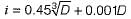
Which one of the following does D stands for- a)the diameter
- b)the geometric mean of diameter steps between which a particular basic size lies
- c)product of the two diameter steps
- d)arithmetic mean of the two diameter steps
Correct answer is option 'B'. Can you explain this answer?
For sizes up to and including 500 mm, the tolerance unit i is determined from the equation
Which one of the following does D stands for
Which one of the following does D stands for
a)
the diameter
b)
the geometric mean of diameter steps between which a particular basic size lies
c)
product of the two diameter steps
d)
arithmetic mean of the two diameter steps
|
|
Pallabi Bajaj answered |
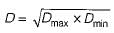
i.e. It is geometric mean of the 2 diameter step.
Which one of the following is not an angle measuring device- a)bevel protector
- b)sine bar
- c)angle gauge blocks
- d)angle iron
Correct answer is option 'D'. Can you explain this answer?
Which one of the following is not an angle measuring device
a)
bevel protector
b)
sine bar
c)
angle gauge blocks
d)
angle iron
|
|
Raghav Mukherjee answered |
Explanation:
An angle measuring device is a tool or instrument that is used to measure or determine the angle between two lines or surfaces. It is an essential tool in various industries and fields, including mechanical engineering.
Let's analyze each option to determine which one is not an angle measuring device:
a) Bevel Protector:
- A bevel protector is a tool used to measure and transfer angles. It consists of a protractor-like device with a level vial attached to it.
- It is used to measure and transfer angles accurately, making it a useful angle measuring device.
b) Sine Bar:
- A sine bar is a precision measuring instrument used to measure angles by utilizing the trigonometric relationship between the length of the sine of an angle and the length of the opposite side of a right triangle.
- It is commonly used in machining operations to set up the workpiece at a specific angle.
c) Angle Gauge Blocks:
- Angle gauge blocks, also known as angle blocks or angle plates, are precision ground blocks of metal that are used to set up and measure angles.
- They are available in various sizes and angles and are used in conjunction with other measuring tools to accurately determine and set angles.
d) Angle Iron:
- Angle iron is a structural steel or aluminum piece that has a right angle shape, similar to the letter 'L'.
- While angle iron is a commonly used material in construction and fabrication, it is not primarily used as an angle measuring device.
Therefore, the correct answer is option 'D' - Angle Iron. It is not an angle measuring device but a structural component.
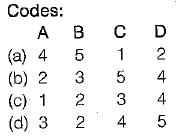
 The respective values of fundamental deviation and tolerance are
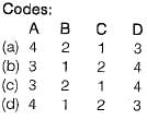
Chapter doubts & questions for Metrology & Inspection - Manufacturing Engineering 2025 is part of Mechanical Engineering exam preparation. The chapters have been prepared according to the Mechanical Engineering exam syllabus. The Chapter doubts & questions, notes, tests & MCQs are made for Mechanical Engineering 2025 Exam. Find important definitions, questions, notes, meanings, examples, exercises, MCQs and online tests here.
Chapter doubts & questions of Metrology & Inspection - Manufacturing Engineering in English & Hindi are available as part of Mechanical Engineering exam.
Download more important topics, notes, lectures and mock test series for Mechanical Engineering Exam by signing up for free.
Manufacturing Engineering
56 videos|80 docs|29 tests
|
|
© EduRev
|
Education Revolution
|


|


Signup on EduRev and stay on top of your study goals
10M+ students crushing their study goals daily