


All Exams >
Mechanical Engineering >
Theory of Machines (TOM) >
All Questions
All questions of Gears for Mechanical Engineering Exam


Match List - I (Terms) with List - II (Definitions) and select the correct answer using the codes given below the lists:
List-I
A. Module
B. Addendum
C. Circular pitch
List-II
1. Radial distance of a tooth from the pitch circle to the top of the tooth
2. Radial distance of a tooth from the pitch circle to the bottom of the tooth
3. Distance on the circumference of the pitch circle from a point of one tooth to the corresponding point on the next tooth
4. Ratio of pitch circle diameter in mm to the number of teeth
Codes:
A B C
(a) 4 1 3
(b) 4 2 3
(c) 3 1 2
(d) 3 2 4- a)(a)
- b)(b)
- c)(c)
- d)(d)
Correct answer is option 'A'. Can you explain this answer?
Match List - I (Terms) with List - II (Definitions) and select the correct answer using the codes given below the lists:
List-I
A. Module
B. Addendum
C. Circular pitch
List-II
1. Radial distance of a tooth from the pitch circle to the top of the tooth
2. Radial distance of a tooth from the pitch circle to the bottom of the tooth
3. Distance on the circumference of the pitch circle from a point of one tooth to the corresponding point on the next tooth
4. Ratio of pitch circle diameter in mm to the number of teeth
Codes:
A B C
(a) 4 1 3
(b) 4 2 3
(c) 3 1 2
(d) 3 2 4
a)
(a)
b)
(b)
c)
(c)
d)
(d)
|
|
Sharmila Chauhan answered |
Explanation:
Module:
- Module is the ratio of pitch circle diameter in mm to the number of teeth.
- It is represented as M = D/N, where M is the module, D is the pitch circle diameter, and N is the number of teeth.
Addendum:
- Addendum is the radial distance of a tooth from the pitch circle to the top of the tooth.
- It is the height of the tooth above the pitch circle.
Circular pitch:
- Circular pitch is the distance on the circumference of the pitch circle from a point of one tooth to the corresponding point on the next tooth.
- It is the distance between corresponding points on adjacent teeth measured along the pitch circle.
Correct answer:
The correct match for each term is:
- Module: Ratio of pitch circle diameter in mm to the number of teeth (4)
- Addendum: Radial distance of a tooth from the pitch circle to the top of the tooth (1)
- Circular pitch: Distance on the circumference of the pitch circle from a point of one tooth to the corresponding point on the next tooth (3)
Therefore, the correct answer is option (a) 4 1 3.
The contact ratio of gears is always - a)more than one
- b)one
- c)less than one
- d)zero
Correct answer is option 'A'. Can you explain this answer?
The contact ratio of gears is always
a)
more than one
b)
one
c)
less than one
d)
zero

|
Milan Ghosh answered |
For continuous transmission of motion, at least one tooth of one wheel must be in contact with another tooth of second wheel. Therefore, the contact ratio must be greater than unity.
If an imaginary circle is drawn which- by pure rolling action gives the same motion as the actual gear, what is the circle called?- a)Addendum circle
- b)Pitch circle
- c)Root circle
- d)Dedendum circle
Correct answer is option 'B'. Can you explain this answer?
If an imaginary circle is drawn which- by pure rolling action gives the same motion as the actual gear, what is the circle called?
a)
Addendum circle
b)
Pitch circle
c)
Root circle
d)
Dedendum circle
|
|
Nayanika Yadav answered |
Pitch Circle: The pitch circle is the curve of intersection of the pitch surface of revolution and the plane of rotation. It is an imaginary circle that rolls without slipping with the pitch circle of a mating gear. The pitch circles of a pair of mating gears are tangent to each other.
Common contact ratio of a pair of spur pinion- a)less than 1
- b)equal to 1
- c)greater than 1
- d)greater than 3
Correct answer is option 'C'. Can you explain this answer?
Common contact ratio of a pair of spur pinion
a)
less than 1
b)
equal to 1
c)
greater than 1
d)
greater than 3
|
|
Gayatri Dasgupta answered |
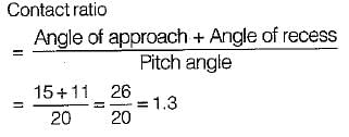
Contract ratio of a pair of spur pinion and gear is usually more than 1.
Here appropriate answer is (c).
Here appropriate answer is (c).
The arrangement is called bevel gearing, when two shafts are- a)intersecting and co-planer
- b)non-intersecting and non-co-planer
- c)parallel and co-planer
- d)parallel and non-co-plane
Correct answer is option 'A'. Can you explain this answer?
The arrangement is called bevel gearing, when two shafts are
a)
intersecting and co-planer
b)
non-intersecting and non-co-planer
c)
parallel and co-planer
d)
parallel and non-co-plane
|
|
Anshu Patel answered |
To have a gear drive between two intersecting shafts bevel gears are used.
The motion transmitted between the teeth of two spur gears is generally- a)sliding
- b)rolling
- c)rotary
- d)party sliding and partly rolling
Correct answer is option 'D'. Can you explain this answer?
The motion transmitted between the teeth of two spur gears is generally
a)
sliding
b)
rolling
c)
rotary
d)
party sliding and partly rolling
|
|
Neha Joshi answered |
Pair of teeth is at pitch point have pure rolling action. At away other position, they have sliding as well as rolling velocity.

Which one of the following is the correct statement?The consequence of a slight increase in the centre distance between two mating involute gears is that.- a)The law of gearing is not satisfied perfectly
- b)Interference occurs
- c)Pressure angle increases ,
- d)Pressure angle decreases
Correct answer is option 'C'. Can you explain this answer?
Which one of the following is the correct statement?
The consequence of a slight increase in the centre distance between two mating involute gears is that.
a)
The law of gearing is not satisfied perfectly
b)
Interference occurs
c)
Pressure angle increases ,
d)
Pressure angle decreases
|
|
Shruti Bose answered |
Interference in involute gear can be avoided by increasing the centre distance. Interference can also be eliminated by increasing the pressure angle.
How does the contact ratio of helical gears compare with that of spur gears?
- a)It is lesser than that of spur gear
- b)It is greater than that of spur gear
- c)Infinite
- d)It is equal to that of spur gear
Correct answer is option 'B'. Can you explain this answer?
How does the contact ratio of helical gears compare with that of spur gears?
a)
It is lesser than that of spur gear
b)
It is greater than that of spur gear
c)
Infinite
d)
It is equal to that of spur gear
|
|
Ruchi Ahuja answered |
Helical gears typically provide a higher contact ratio than spur gears. This is due to the additional axial contact ratio resulting from their angled teeth, keeping more teeth in contact at the mesh point for a longer duration.
Select the positive drive amongst the following:- a)rope drive
- b)V-belt drive
- c)chain drive
- d)gear drive
Correct answer is option 'D'. Can you explain this answer?
Select the positive drive amongst the following:
a)
rope drive
b)
V-belt drive
c)
chain drive
d)
gear drive
|
|
Sagarika Dey answered |
Gear drives use no intermediate link or connector and transmit the motion by direct contact. Hence, gears ensure definite velocity ratio and provide a positive drive.
Th e tooth profile most commonly used in gear drive for power transmission is- a)a cycloid
- b)an involute .
- c)an ellipse
- d)a parabola
Correct answer is option 'B'. Can you explain this answer?
Th e tooth profile most commonly used in gear drive for power transmission is
a)
a cycloid
b)
an involute .
c)
an ellipse
d)
a parabola

|
Rithika Kaur answered |
Due to ease of standadization, manufacturing and low cost of production, the use of involute te e th has becom e universal by e n tire ly superseding the cycloidal teeth shape.
In the case of an involute toothed gear, involute starts from- a)Addendum circle
- b)Dedendum circle
- c)Pitch circle
- d)Base circle
Correct answer is option 'D'. Can you explain this answer?
In the case of an involute toothed gear, involute starts from
a)
Addendum circle
b)
Dedendum circle
c)
Pitch circle
d)
Base circle
|
|
Debolina Menon answered |
In case of involute toothed gear base circle is the circle above which profile of gear is involute and below the base circle straight line exists. Hence it is the base circle.
Consider the following statements:
1. A stub both has working depth larger than that of a full depth tooth.
2. The path of contact for involute gears is an arc of a circle.
Which of these statements is/are correct?- a)1 only
- b)2 only
- c)Both 1 and 2
- d)Neither 1 and 2
Correct answer is option 'D'. Can you explain this answer?
Consider the following statements:
1. A stub both has working depth larger than that of a full depth tooth.
2. The path of contact for involute gears is an arc of a circle.
Which of these statements is/are correct?
1. A stub both has working depth larger than that of a full depth tooth.
2. The path of contact for involute gears is an arc of a circle.
Which of these statements is/are correct?
a)
1 only
b)
2 only
c)
Both 1 and 2
d)
Neither 1 and 2
|
|
Arjun Menon answered |
1. A stub tooth has working depth smaller than that of a full depth tooth.
2. The path of contact for involute gears is a straight line.
2. The path of contact for involute gears is a straight line.
For a cycloidal tooth profile, pressure angle at
I. Commencement of engagement
II. Pitch point and
III. At the end of engagement will be- a)Constant
- b)Zero, maximum, zero
- c)Max, zero, max
- d)Max zero, min
Correct answer is option 'C'. Can you explain this answer?
For a cycloidal tooth profile, pressure angle at
I. Commencement of engagement
II. Pitch point and
III. At the end of engagement will be
I. Commencement of engagement
II. Pitch point and
III. At the end of engagement will be
a)
Constant
b)
Zero, maximum, zero
c)
Max, zero, max
d)
Max zero, min
|
|
Kirti Bose answered |
For a cycloidal tooth profile pressure angle is zero at the pitch point and becomes maximum during the engagement and disengagement.
The difference between space width and tooth thickness is- a)Backlash
- b)Clearance
- c)Flank
- d)Tooth space
Correct answer is option 'A'. Can you explain this answer?
The difference between space width and tooth thickness is
a)
Backlash
b)
Clearance
c)
Flank
d)
Tooth space
|
|
Avik Ghosh answered |
Backlash:
Backlash refers to the play or clearance between mating gear teeth. It is the difference in the tooth space width and the tooth thickness.
Definition:
Backlash is the amount of movement or "play" between the teeth of two gears when they are engaged with each other. It is essentially the clearance between the mating gear teeth. Backlash is important to consider in gear design and manufacturing as it affects the overall performance and efficiency of the gear system.
Space Width:
Space width is the width of the space between two adjacent gear teeth. It is the measurement from the flank of one tooth to the flank of the adjacent tooth. Space width can be measured at the pitch circle or any other reference point on the gear.
Tooth Thickness:
Tooth thickness is the width of an individual gear tooth. It is the measurement from the tip of the tooth to the root. Tooth thickness can also be measured at the pitch circle or any other reference point on the gear.
Difference between Space Width and Tooth Thickness:
The difference between space width and tooth thickness is referred to as backlash. It represents the amount of clearance or play between the mating gear teeth. Backlash is necessary to ensure smooth and efficient operation of the gear system.
When the gear teeth are engaged, the tooth thickness of one gear should fit perfectly into the space width of the mating gear. However, in reality, there is always a slight gap or clearance between the teeth due to manufacturing tolerances, wear, and other factors. This gap is the backlash.
Importance of Backlash:
Backlash is important to consider in gear design because it affects the performance and reliability of the gear system. A small amount of backlash is necessary to prevent binding or jamming of the gears. It allows for thermal expansion, lubrication, and variations in operating conditions.
However, excessive backlash can result in undesirable effects such as noise, vibration, and reduced efficiency. It can lead to inaccurate positioning and decreased precision in gear systems. Therefore, it is crucial to carefully control and optimize the amount of backlash in gear design and manufacturing to achieve the desired performance and reliability.
For an involute gear, the ratio, pitch circle radius/ base circle radius is (φ is the pressure angle)- a)sinφ
- b)costφ
- c)secφ
- d)cosecφ
Correct answer is option 'C'. Can you explain this answer?
For an involute gear, the ratio, pitch circle radius/ base circle radius is (φ is the pressure angle)
a)
sinφ
b)
costφ
c)
secφ
d)
cosecφ
|
|
Mansi Kulkarni answered |
Base circle radius = Pitch circle radius x cos φ
Ratio of pitch circle diameter in millimeters to the number of teeth is known as- a)module
- b)circular pitch
- c)diametral pitch
- d)clearance
Correct answer is option 'A'. Can you explain this answer?
Ratio of pitch circle diameter in millimeters to the number of teeth is known as
a)
module
b)
circular pitch
c)
diametral pitch
d)
clearance
|
|
Mahi Kaur answered |
Module = D/T
where
D = Pitch circle diameter
T = Number of teeth
where
D = Pitch circle diameter
T = Number of teeth
When two spur gears having involute profiles on their teeth engaged, the line of action is tangential to the- a)Pitch circles
- b)Dedendum circles
- c)Addendum circles
- d)Base circle
Correct answer is option 'D'. Can you explain this answer?
When two spur gears having involute profiles on their teeth engaged, the line of action is tangential to the
a)
Pitch circles
b)
Dedendum circles
c)
Addendum circles
d)
Base circle
|
|
Avantika Sen answered |
Two important properties of an involute
(i) A normal to an involute is a tangent to the basic circle
(ii) The radius of curvature of an involute is equal to the length of the tangent to the base circle.
(i) A normal to an involute is a tangent to the basic circle
(ii) The radius of curvature of an involute is equal to the length of the tangent to the base circle.
A rack is a gear of infinite- a)Pitch
- b)Module
- c)Diameter
- d)Number of teeth
Correct answer is option 'C'. Can you explain this answer?
A rack is a gear of infinite
a)
Pitch
b)
Module
c)
Diameter
d)
Number of teeth
|
|
Jyoti Deshpande answered |
Rack is defined as a gear of infinite diameter.
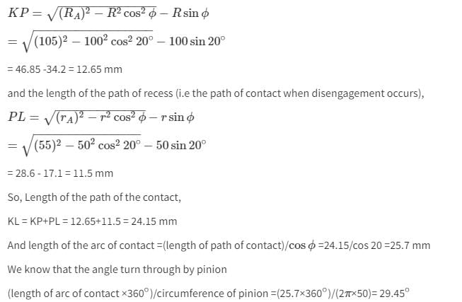
Two involute gears of 20° pressure angle are in mesh. The number of teeth on pinion is 20 and gear ratio is 2. If the module is 5 mm and pitch line speed is 1.2 m/s, (Assume addendum as standard and equal to one module). Then angle turned through the pinion when one pair of teeth is in mesh, will be
- a)27.55°
- b)28.35°
- c)29.45°
- d)32.65°
Correct answer is option 'C'. Can you explain this answer?
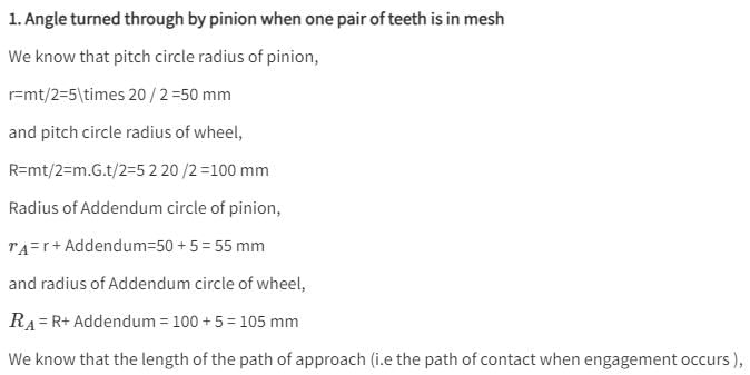
Two involute gears of 20° pressure angle are in mesh. The number of teeth on pinion is 20 and gear ratio is 2. If the module is 5 mm and pitch line speed is 1.2 m/s, (Assume addendum as standard and equal to one module). Then angle turned through the pinion when one pair of teeth is in mesh, will be
a)
27.55°
b)
28.35°
c)
29.45°
d)
32.65°

|
Constructing Careers answered |
The difference between addendum and dedendum is known as- a)Backlash
- b)Clearance .
- c)Fiank
- d)Tooth space
Correct answer is option 'B'. Can you explain this answer?
The difference between addendum and dedendum is known as
a)
Backlash
b)
Clearance .
c)
Fiank
d)
Tooth space
|
|
Divya Banerjee answered |
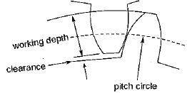
Clearance is the amount by which the dedendum of a gear exceeds the addendum of its mating tooth.
In case of a gear pair with involute tooth profile, the pressure angle through out the contact is- a)constant
- b)maximum at the pitch point
- c)minimum at the pitch point
- d)zero at the pitch point
Correct answer is option 'A'. Can you explain this answer?
In case of a gear pair with involute tooth profile, the pressure angle through out the contact is
a)
constant
b)
maximum at the pitch point
c)
minimum at the pitch point
d)
zero at the pitch point
|
|
Dipika Kulkarni answered |
In involute profile of gear teeth pressure angle is constant throughout the engagement of teeth. This results in smooth running of the gear.
For a single reduction spur gear, the gear ratio is 10 to 1 and the center distance is 330 mm. The nearest standard module if no interference is to occur, will be- a)1
- b)2
- c)3
- d)4
Correct answer is option 'D'. Can you explain this answer?
For a single reduction spur gear, the gear ratio is 10 to 1 and the center distance is 330 mm. The nearest standard module if no interference is to occur, will be
a)
1
b)
2
c)
3
d)
4
|
|
Tarun Chatterjee answered |
Explanation:
The gear ratio is defined as the ratio of the number of teeth on the driving gear to the number of teeth on the driven gear. In this case, the gear ratio is given as 10 to 1, which means that the driving gear has 10 teeth and the driven gear has 1 tooth.
The center distance is the distance between the centers of the two gears. In this case, the center distance is given as 330 mm.
To determine the module of the gear, we can use the formula:
Module = Center Distance / (Number of Teeth on the Driving Gear + Number of Teeth on the Driven Gear)
Using the given values, we can substitute them into the formula:
Module = 330 mm / (10 + 1)
Module = 330 mm / 11
Module ≈ 30 mm
Since the module is the closest standard module, we need to round it to the nearest standard module. In this case, the nearest standard module is 4.
Therefore, the correct answer is option 'D' - 4.
Summary:
To determine the nearest standard module for a single reduction spur gear with a gear ratio of 10 to 1 and a center distance of 330 mm, we can use the formula for module. By substituting the given values into the formula, we find that the module is approximately 30 mm. Since the nearest standard module is 4, the correct answer is option 'D'.
The gear ratio is defined as the ratio of the number of teeth on the driving gear to the number of teeth on the driven gear. In this case, the gear ratio is given as 10 to 1, which means that the driving gear has 10 teeth and the driven gear has 1 tooth.
The center distance is the distance between the centers of the two gears. In this case, the center distance is given as 330 mm.
To determine the module of the gear, we can use the formula:
Using the given values, we can substitute them into the formula:
Since the module is the closest standard module, we need to round it to the nearest standard module. In this case, the nearest standard module is 4.
Therefore, the correct answer is option 'D' - 4.
Summary:
To determine the nearest standard module for a single reduction spur gear with a gear ratio of 10 to 1 and a center distance of 330 mm, we can use the formula for module. By substituting the given values into the formula, we find that the module is approximately 30 mm. Since the nearest standard module is 4, the correct answer is option 'D'.
The size of Gear is specified by- a)Circular pitch
- b)Diametral pitch
- c)Module
- d)All of the above
Correct answer is option 'D'. Can you explain this answer?
The size of Gear is specified by
a)
Circular pitch
b)
Diametral pitch
c)
Module
d)
All of the above
|
|
Dishani Desai answered |
Size of gear is specified by its pitch and pitch can be classified as
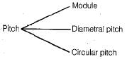
Hence circular pitch, diametral pitch and module represents size of gear.
Hence circular pitch, diametral pitch and module represents size of gear.
For helical gears, the helix angle generally ranges from- a)00 to 300
- b)300 to 450
- c)450 to 600
- d)300 to 750
Correct answer is option 'A'. Can you explain this answer?
For helical gears, the helix angle generally ranges from
a)
00 to 300
b)
300 to 450
c)
450 to 600
d)
300 to 750
|
|
Rishika Sen answered |
Helical gears are a type of gear system that have teeth that are not parallel to the axis of rotation, but instead are aligned at an angle. This angle is known as the helix angle. The helix angle affects the performance and characteristics of the gear system, including its load-carrying capacity, efficiency, and noise level.
The helix angle generally ranges from 0° to 30° for helical gears. Let's understand why this is the case:
1. Definition and Purpose of Helical Gears:
- Helical gears are cylindrical gears with teeth that are cut at an angle to the gear axis.
- The purpose of the helix angle is to introduce a sliding action between the teeth during contact, which helps in reducing noise and increasing the load-carrying capacity of the gears.
2. Helix Angle Range:
- The helix angle for helical gears typically ranges from 0° to 30°.
- The lower limit of 0° corresponds to a gear system with straight teeth, which is essentially a spur gear.
- The upper limit of 30° is a practical limit beyond which the sliding action between the teeth becomes too significant, leading to increased friction and wear.
- In some special cases, the helix angle can go beyond 30°, but these are not common and have specific applications.
3. Gear Performance Considerations:
- As the helix angle increases, the load-carrying capacity of the gear system improves due to the larger tooth contact area.
- However, increasing the helix angle also increases the axial thrust force, which needs to be properly managed in the gear design.
- The helix angle also affects the efficiency of the gear system, with higher angles generally resulting in slightly lower efficiency.
- Additionally, the helix angle influences the noise level of the gear system, with lower angles leading to quieter operation.
In conclusion, the helix angle for helical gears generally ranges from 0° to 30°. This range provides a balance between load-carrying capacity, efficiency, and noise level in the gear system.
The size of gears is usually specified by- a)circular pitch
- b)addendum circle diameter
- c)pitch circle diameter
- d)base circle diameter
Correct answer is option 'C'. Can you explain this answer?
The size of gears is usually specified by
a)
circular pitch
b)
addendum circle diameter
c)
pitch circle diameter
d)
base circle diameter
|
|
Ashutosh Sharma answered |
Pitch Circle Diameter as the Size of Gears
Explanation:
Gears are important mechanical components used in machines to transmit power and motion from one shaft to another. The size of gears is a crucial factor that determines their performance, efficiency, and compatibility with other gears. The most commonly used parameter for specifying the size of gears is the pitch circle diameter.
Pitch Circle Diameter (PCD):
The pitch circle is an imaginary circle that passes through the points of contact of two mating gears. The diameter of this circle is known as the pitch circle diameter (PCD) and is used to determine the size of gears. The PCD is measured in millimeters (mm) or inches (in) depending on the system of units used.
How PCD is Determined:
The pitch circle diameter is determined by considering the number of teeth on the gear, the module or diametral pitch, and the pressure angle. The module is a metric parameter that relates the size of the gear to the number of teeth and is defined as the ratio of the pitch circle diameter to the number of teeth. The diametral pitch is an imperial parameter that relates the number of teeth to the pitch circle diameter and is defined as the number of teeth per inch of diameter. The pressure angle is the angle between the line of action of the teeth and a tangent to the pitch circle.
Advantages of PCD:
The use of pitch circle diameter as a parameter for specifying the size of gears offers several advantages. Firstly, it provides a standard method for determining the size of gears that is universally accepted. Secondly, it enables the gears to be easily matched with other gears for compatibility. Thirdly, it helps in the design of gear systems by enabling the calculation of gear ratios and tooth profiles.
Conclusion:
In conclusion, the pitch circle diameter is the most commonly used parameter for specifying the size of gears. It is determined by considering the number of teeth, module or diametral pitch, and pressure angle. The use of pitch circle diameter offers several advantages in terms of standardization, compatibility, and design of gear systems.
The ends of gears are made slightly thinner (crowning). This is done - a)only in case of high speed gears
- b)to have a better surface finish
- c)to increase the pressure angle
- d)to make the teeth stronger and increase its service life
Correct answer is option 'D'. Can you explain this answer?
The ends of gears are made slightly thinner (crowning). This is done
a)
only in case of high speed gears
b)
to have a better surface finish
c)
to increase the pressure angle
d)
to make the teeth stronger and increase its service life
|
|
Moumita Rane answered |
The Purpose of Crowning Gears
Crowning is a process in which the ends of gears are made slightly thinner. This technique is employed for various reasons, but the primary purpose is to make the gear teeth stronger and increase their service life. Let's delve into the details of why crowning is done and how it achieves this objective.
1. Distribution of Load
By crowning the gear teeth, the load distribution across the tooth face becomes more uniform. In a non-crowned gear, the load is concentrated at the center of the tooth face, leading to higher stresses and potential wear in that region. Crowning ensures that the load is distributed more evenly, reducing stress concentrations and enhancing the overall strength of the gear teeth.
2. Contact Ratio
Another advantage of crowning gears is that it increases the contact ratio. The contact ratio refers to the number of pairs of teeth in contact at any given moment. By crowning the gear teeth, the contact ratio is improved, which helps to distribute the load over a larger area, reducing the pressure on individual teeth. This results in a higher load-carrying capacity for the gear and increases its service life.
3. Noise Reduction
Crowning also contributes to noise reduction in gear systems. When gears mesh, there is a possibility of misalignment due to manufacturing tolerances or deflections. Crowning compensates for these misalignments by allowing the gear teeth to roll slightly, reducing the sliding and resulting in quieter operation.
4. Improved Lubrication
Crowned gears facilitate better lubrication. The thinner ends of the gear teeth create a space between the mating gears, allowing lubricant to flow more effectively and reach all contact surfaces. This helps to reduce friction, wear, and heat generation, thereby improving the gear's efficiency and longevity.
Conclusion
In summary, crowning gears is done to make the teeth stronger and increase their service life. It achieves this by distributing the load more evenly, increasing the contact ratio, reducing noise, and improving lubrication. By incorporating these design modifications, gears can operate more efficiently and reliably, providing enhanced performance and longevity in various mechanical systems.
Tumbler gears are- a)bevel gears having the same module
- b)gears in lathe machine used for reversing the direction of rotation of driven gears
- c)gears in lathe head stock used to reduce the speed of spindle
- d)pair of gears in a machine that serves to connect the dividing head with table movement
Correct answer is option 'B'. Can you explain this answer?
Tumbler gears are
a)
bevel gears having the same module
b)
gears in lathe machine used for reversing the direction of rotation of driven gears
c)
gears in lathe head stock used to reduce the speed of spindle
d)
pair of gears in a machine that serves to connect the dividing head with table movement
|
|
Shruti Bose answered |
Tumbler gears in a lathe machine
Explanation:
Tumbler gears are a crucial component in a lathe machine that is used to reverse the direction of rotation of driven gears. These gears are typically located in the gearbox of the lathe machine and are responsible for changing the direction of rotation of the spindle.
Function of tumbler gears:
The main function of tumbler gears is to allow the lathe machine to perform operations such as thread cutting, where the direction of rotation of the workpiece needs to be reversed. By engaging the tumbler gears, the operator can reverse the rotation of the gears, resulting in the reversal of the workpiece's rotation.
Working mechanism:
The tumbler gears consist of a pair of gears that are mounted on a shaft. These gears are usually of the same module, meaning they have the same pitch diameter and tooth size. When the lathe machine is in operation, the gears are engaged with the driven gears, which are connected to the spindle.
Engaging the tumbler gears:
To reverse the direction of rotation, the operator needs to disengage the spindle from the powered gears and engage it with the tumbler gears. This is typically done by shifting a lever or engaging a clutch mechanism. Once the tumbler gears are engaged, the rotation of the spindle is reversed, causing the workpiece to rotate in the opposite direction.
Applications:
The use of tumbler gears in a lathe machine is essential for various operations, including thread cutting, knurling, and reverse turning. These operations require the workpiece to rotate in the opposite direction, and the tumbler gears enable this functionality.
In summary, tumbler gears are bevel gears in a lathe machine that are used to reverse the direction of rotation of the driven gears. They play a crucial role in enabling operations such as thread cutting and allow for versatility in the lathe machine's functionality.
Tooth interference in an external involute spur gear pair can be reduced by- a)decreasing center distance between gear pair
- b)decreasing module
- c)decreasing pressure angle
- d)increasing number of gear teeth
Correct answer is option 'D'. Can you explain this answer?
Tooth interference in an external involute spur gear pair can be reduced by
a)
decreasing center distance between gear pair
b)
decreasing module
c)
decreasing pressure angle
d)
increasing number of gear teeth
|
|
Kiran Basu answered |
Increasing number of gear teeth:
Increasing the number of gear teeth in an external involute spur gear pair can help reduce tooth interference. This is because having more teeth distributes the load over a larger area, reducing the likelihood of interference between teeth.
Explanation:
- In a gear pair, the number of teeth on each gear affects the contact ratio, which is the ratio of the arc of action to the circular pitch. A higher contact ratio indicates smoother operation and less likelihood of tooth interference.
- By increasing the number of gear teeth, the contact ratio is increased, which helps in reducing tooth interference.
- Additionally, having more teeth also allows for smaller individual tooth profiles, which can help in reducing the chances of interference between adjacent teeth.
Other options:
- Decreasing center distance between gear pair: Decreasing the center distance between the gear pair can help in reducing backlash and increasing the meshing stiffness, but it may not directly address the issue of tooth interference.
- Decreasing module: Decreasing the module results in smaller gear teeth, which may increase the chances of tooth interference rather than reducing it.
- Decreasing pressure angle: The pressure angle affects the tooth profile and strength of the gears but may not have a direct impact on reducing tooth interference.
If D is pitch circle diameter and T is the number of teeth then its circular pitch is- a)πT/D
- b)πD/T
- c)D/T
- d)T/D
Correct answer is option 'B'. Can you explain this answer?
If D is pitch circle diameter and T is the number of teeth then its circular pitch is
a)
πT/D
b)
πD/T
c)
D/T
d)
T/D
|
|
Anand Kumar answered |
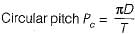
where
D = Pitch circle diameter
T = Number of teeth
The stub tooth is- a)a non-standard profile of tooth
- b)a basic rack of straight sides except for the fillet arc
- c)longer than standard tooth-depth
- d)shorter than standard tooth-depth
Correct answer is option 'D'. Can you explain this answer?
The stub tooth is
a)
a non-standard profile of tooth
b)
a basic rack of straight sides except for the fillet arc
c)
longer than standard tooth-depth
d)
shorter than standard tooth-depth
|
|
Priyanka Tiwari answered |
20° stub involute system have following features:
- Shorter addendum and shorter dedendum
- Smaller interference as compared to full depth involute
- Drive is more compact
- Stronger than full depth involute teeth
- Lower production cost as less metal must be cut away
The main draw back of this system is that the contact ratio is reduced due to shorter addendum.
Large pressure angle of the gear results in- a)Weaker teeth
- b)Wider base and stronger teeth
- c)Bigger size of gear
- d)Smaller size of gear
Correct answer is option 'B'. Can you explain this answer?
Large pressure angle of the gear results in
a)
Weaker teeth
b)
Wider base and stronger teeth
c)
Bigger size of gear
d)
Smaller size of gear
|
|
Nayanika Yadav answered |
Explanation:
When discussing gears, the pressure angle refers to the angle between the line of action and the common tangent to the pitch circles of two meshing gears. The pressure angle affects several factors related to gear design and performance.
1. Definition of pressure angle:
The pressure angle is defined as the angle between the direction of the force acting on the gear tooth and the line perpendicular to the tooth surface at the point of contact. It is typically measured in degrees.
2. Effect on gear strength:
The pressure angle has a significant impact on the strength of the gear teeth. A larger pressure angle results in wider gear teeth, which increases the contact area between the meshing gears. This wider base provides better load distribution across the tooth face, resulting in stronger teeth that can withstand higher loads without deformation or failure.
3. Effect on gear size:
A larger pressure angle leads to a wider gear base, which requires a larger gear size. This means that gears with a large pressure angle will have a larger diameter and overall size compared to gears with a smaller pressure angle.
4. Other considerations:
While a larger pressure angle can improve gear strength, there are some trade-offs to consider. Gears with a larger pressure angle may experience increased sliding and friction during operation, which can lead to higher power losses and reduced efficiency. Additionally, larger pressure angles may require modifications to the gear design, such as stronger materials or increased tooth thickness, which can increase the cost and complexity of gear manufacturing.
Conclusion:
In summary, a larger pressure angle in gears results in wider gear teeth, which provide a stronger base and better load distribution. However, it also leads to larger gear size and potential drawbacks such as increased sliding and manufacturing complexities. Hence, option 'B' is the correct answer as it accurately describes the impact of a large pressure angle on gear design.
The gears are interchangeable if they have- a)the same module and pressure angle
- b)the same module, pressure angle, addendums and dedendumes
- c)the same module and thickness
- d)the module, pressure angle, addendums, dedendums and same thickness
Correct answer is option 'D'. Can you explain this answer?
The gears are interchangeable if they have
a)
the same module and pressure angle
b)
the same module, pressure angle, addendums and dedendumes
c)
the same module and thickness
d)
the module, pressure angle, addendums, dedendums and same thickness
|
|
Aditya Jain answered |
Interchangeability of Gears
Gears are mechanical components that transmit power and motion between two rotating shafts. Interchangeability of gears is an important aspect of gear design and manufacturing. Interchangeability ensures that gears can be easily replaced without the need for costly modifications or adjustments.
Factors affecting Interchangeability of Gears
There are several factors that affect the interchangeability of gears. These include:
1. Module - The module is the ratio of the pitch diameter to the number of teeth in a gear. Gears with the same module can be interchanged.
2. Pressure Angle - The pressure angle is the angle between the line of action and the tangent to the pitch circle of a gear. Gears with the same pressure angle can be interchanged.
3. Addendums and Dedendums - The addendum is the distance between the pitch circle and the top of the gear tooth. The dedendum is the distance between the pitch circle and the bottom of the gear tooth. Gears with the same addendums and dedendums can be interchanged.
4. Thickness - The thickness of the gears must also be the same to ensure interchangeability.
Therefore, the correct option for the given question is option 'D', which includes all the factors affecting the interchangeability of gears.
If a reduction ratio of about 50 is required in a gear drive then the most appropriate gearing would be- a) spur gears
- b) bevel gears
- c) double helical gears
- d) worm and worm wheel
Correct answer is option 'D'. Can you explain this answer?
If a reduction ratio of about 50 is required in a gear drive then the most appropriate gearing would be
a)
spur gears
b)
bevel gears
c)
double helical gears
d)
worm and worm wheel
|
|
Nishanth Basu answered |
Reduction Ratio and Gear Types
Reduction ratio refers to the ratio of the number of teeth on the driven gear to the number of teeth on the driving gear. A reduction ratio of 50 means that the driven gear has 50 times fewer teeth than the driving gear. In this case, the most appropriate gearing would be worm and worm wheel.
Worm and Worm Wheel Gearing
Worm and worm wheel gearing is a type of gearing in which a worm (a type of screw) meshes with a worm wheel (a type of gear). The worm has a helical thread that wraps around the circumference of a cylindrical shaft, while the worm wheel has teeth that mesh with the worm. The worm wheel is usually made of bronze or other soft metals, while the worm is made of steel or other hard metals.
Advantages of Worm and Worm Wheel Gearing
1. High Reduction Ratio: Worm and worm wheel gearing can achieve very high reduction ratios, making it suitable for applications where a large speed reduction is required.
2. Compact Design: Worm and worm wheel gearing has a compact design, which allows for the use of smaller and lighter components.
3. Self-Locking: Worm and worm wheel gearing is self-locking, which means that the gear cannot be turned by the worm when the drive is stopped. This makes it ideal for applications where there is a need for holding a load in a fixed position.
4. Smooth Operation: Worm and worm wheel gearing operates smoothly and quietly, making it ideal for applications where noise and vibration are a concern.
Disadvantages of Worm and Worm Wheel Gearing
1. Lower Efficiency: Worm and worm wheel gearing has a lower efficiency compared to other types of gearing, which means that more power is lost in the form of heat.
2. Limited Speed: Worm and worm wheel gearing has a limited speed range, which makes it unsuitable for high-speed applications.
Conclusion
In conclusion, if a reduction ratio of about 50 is required in a gear drive, the most appropriate gearing would be worm and worm wheel. This type of gearing has a high reduction ratio, a compact design, is self-locking, and operates smoothly. However, it has a lower efficiency and a limited speed range.


Chapter doubts & questions for Gears - Theory of Machines (TOM) 2025 is part of Mechanical Engineering exam preparation. The chapters have been prepared according to the Mechanical Engineering exam syllabus. The Chapter doubts & questions, notes, tests & MCQs are made for Mechanical Engineering 2025 Exam. Find important definitions, questions, notes, meanings, examples, exercises, MCQs and online tests here.
Chapter doubts & questions of Gears - Theory of Machines (TOM) in English & Hindi are available as part of Mechanical Engineering exam.
Download more important topics, notes, lectures and mock test series for Mechanical Engineering Exam by signing up for free.
Theory of Machines (TOM)
87 videos|85 docs|29 tests
|
|
© EduRev
|
Education Revolution
|


|


Signup on EduRev and stay on top of your study goals
10M+ students crushing their study goals daily