


All Exams >
Mechanical Engineering >
Solid Mechanics >
All Questions
All questions of Bending & Shear Stress in Beams for Mechanical Engineering Exam
A beam with a square section of 80 mm x 80 mm is simply supported at its ends. A load W is applied at the centre of the beam. If the maximum shear stress developed in the beam section is 6 N/mm2. What is the magnitude of W?- a)2.56 kN
- b)25.6 kN
- c)-51.2kN
- d)5.12 kN
Correct answer is option 'C'. Can you explain this answer?
A beam with a square section of 80 mm x 80 mm is simply supported at its ends. A load W is applied at the centre of the beam. If the maximum shear stress developed in the beam section is 6 N/mm2. What is the magnitude of W?
a)
2.56 kN
b)
25.6 kN
c)
-51.2kN
d)
5.12 kN

|
Saptarshi Khanna answered |
Given data:
Dimensions of the square section of the beam = 80 mm x 80 mm
Maximum shear stress developed in the beam section = 6 N/mm2
We need to find the magnitude of the load W.
Formula used:
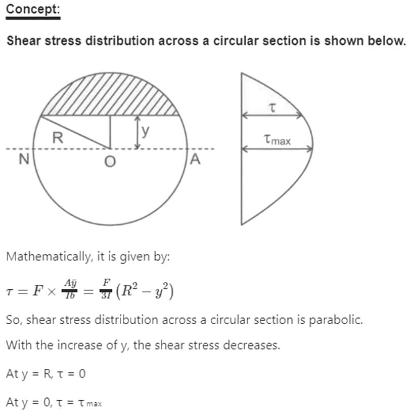
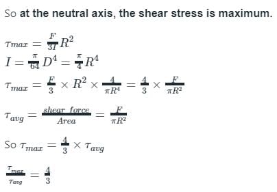
Maximum shear stress (τmax) = (4/3) x (Shear force (V) / Area of cross-section (A))
Calculation:
Area of cross-section (A) = 80 mm x 80 mm = 6400 mm2
Shear force (V) at the center of the beam = W/2
Substituting the given values in the formula, we get:
6 = (4/3) x (W/2) / 6400
W/2 = 6 x 6400 x 3 / 4
W/2 = 72,000
W = 2 x 72,000
W = -144,000 N
Therefore, the magnitude of the load W is -51.2 kN (Option C).
Explanation:
The given beam is simply supported at its ends and has a square cross-section of 80 mm x 80 mm. The load W is applied at the center of the beam. The maximum shear stress developed in the beam section is 6 N/mm2. To find the magnitude of the load W, we use the formula for maximum shear stress and substitute the given values. On solving the equation, we get the magnitude of the load W as -51.2 kN. The negative sign indicates that the load is acting downwards.
Dimensions of the square section of the beam = 80 mm x 80 mm
Maximum shear stress developed in the beam section = 6 N/mm2
We need to find the magnitude of the load W.
Formula used:
Maximum shear stress (τmax) = (4/3) x (Shear force (V) / Area of cross-section (A))
Calculation:
Area of cross-section (A) = 80 mm x 80 mm = 6400 mm2
Shear force (V) at the center of the beam = W/2
Substituting the given values in the formula, we get:
6 = (4/3) x (W/2) / 6400
W/2 = 6 x 6400 x 3 / 4
W/2 = 72,000
W = 2 x 72,000
W = -144,000 N
Therefore, the magnitude of the load W is -51.2 kN (Option C).
Explanation:
The given beam is simply supported at its ends and has a square cross-section of 80 mm x 80 mm. The load W is applied at the center of the beam. The maximum shear stress developed in the beam section is 6 N/mm2. To find the magnitude of the load W, we use the formula for maximum shear stress and substitute the given values. On solving the equation, we get the magnitude of the load W as -51.2 kN. The negative sign indicates that the load is acting downwards.

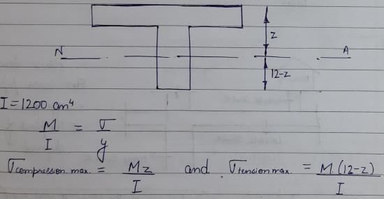
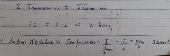
A beam of T-section has I = 1200 cm4 and depth = 12 cm. Flange of the section is in compression. If the maximum tensile stress is two times the maximum compressive stress, what is section modulus in compression?- a)300 cm3
- b)200 cm3
- c)100 cm3
- d)None of these
Correct answer is option 'A'. Can you explain this answer?
A beam of T-section has I = 1200 cm4 and depth = 12 cm. Flange of the section is in compression. If the maximum tensile stress is two times the maximum compressive stress, what is section modulus in compression?
a)
300 cm3
b)
200 cm3
c)
100 cm3
d)
None of these
|
|
Sanvi Kapoor answered |
A beam of rectangular cross-section is 100 mm wide and 200 mm deep. If the section is subjected to a shear force of 20 kN, the maximum shear stress is- a)1 N/mm2
- b)1.125 N/mm2
- c)1.33 N/mm2
- d)1.5 N/mm2
Correct answer is option 'D'. Can you explain this answer?
A beam of rectangular cross-section is 100 mm wide and 200 mm deep. If the section is subjected to a shear force of 20 kN, the maximum shear stress is
a)
1 N/mm2
b)
1.125 N/mm2
c)
1.33 N/mm2
d)
1.5 N/mm2
|
|
Ankit Joshi answered |
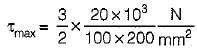
The maximum shear stress in a rectangular beam occurs at NA and is given by,
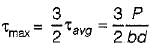
∴
= 1.5 N/mm2
∴
= 1.5 N/mm2
Hence option (D) is correct
For studying more on Bending and Shear stress click on the link given below:
A MS beam is subjected to a bending moment, such that a stress of 100 MPa is developed in a layer at a distance of 100 mm from the neutral layer. If E= 200 GPa, what is the radius of curvature of the beam?: .- a)400 m
- b)200 m
- c)100 m .
- d)50 m
Correct answer is option 'B'. Can you explain this answer?
A MS beam is subjected to a bending moment, such that a stress of 100 MPa is developed in a layer at a distance of 100 mm from the neutral layer. If E= 200 GPa, what is the radius of curvature of the beam?: .
a)
400 m
b)
200 m
c)
100 m .
d)
50 m

|
Subhankar Malik answered |
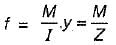
To find the radius of curvature of the beam, we can use the formula for the stress developed in a layer of a beam under bending:
σ = (E * r) / c
Where:
- σ is the stress developed in the layer
- E is the modulus of elasticity of the material
- r is the radius of curvature of the beam
- c is the distance from the neutral axis to the layer
Given that the stress is 100 MPa, the distance from the neutral layer is 100 mm, and the modulus of elasticity is 200 GPa, we can rearrange the formula to solve for the radius of curvature:
r = (σ * c) / E
Substituting the given values, we have:
r = (100 MPa * 100 mm) / (200 GPa)
Converting the units to Pascal and meters:
r = (100 * 10^6 Pa * 0.1 m) / (200 * 10^9 Pa)
Simplifying:
r = 0.05 m
Therefore, the radius of curvature of the beam is 0.05 m, which is equivalent to 200 m.
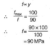
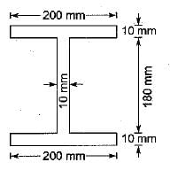
A beam is of i-section with flanges 200 mm x 10 mm and web 180 mm x 10 mm. Due to the bending moment applied on the beam section, maximum stress developed in the beam section is 100 MPa, what is the stress developed at inner edge of the flange?- a)110 MPa
- b)100 MPa
- c)90 MPa
- d)120 MPa
Correct answer is option 'C'. Can you explain this answer?
A beam is of i-section with flanges 200 mm x 10 mm and web 180 mm x 10 mm. Due to the bending moment applied on the beam section, maximum stress developed in the beam section is 100 MPa, what is the stress developed at inner edge of the flange?
a)
110 MPa
b)
100 MPa
c)
90 MPa
d)
120 MPa
|
|
Partho Jain answered |
A cantilever of uniform strength σ, having rectangular section of constant breadth b but variable depth d is subjected to a UDL throughout its length. If the depth of the section is 150 mm at the fixed end, then what is the depth of the middle of the length of cantilever- a)150 mm
- b)100 mm
- c)75 mm
- d)125 mm
Correct answer is option 'C'. Can you explain this answer?
A cantilever of uniform strength σ, having rectangular section of constant breadth b but variable depth d is subjected to a UDL throughout its length. If the depth of the section is 150 mm at the fixed end, then what is the depth of the middle of the length of cantilever
a)
150 mm
b)
100 mm
c)
75 mm
d)
125 mm

|
Aditi Sarkar answered |
A cantilever of uniform strength is a beam that is fixed at one end and extends horizontally, with a cross-sectional area that remains constant throughout its length. This means that the beam has the same strength and stiffness at every point along its length, making it ideal for supporting loads that are distributed evenly across its surface.
The strength of a cantilever beam is determined by its cross-sectional area, material properties, and length. The longer the beam, the greater the bending moment that it can withstand before it fails. The material properties of the beam, such as its modulus of elasticity and yield strength, also play a significant role in determining its strength.
A cantilever beam of uniform strength is often used in construction applications, such as in the design of bridges, buildings, and other structures. These beams can be made from a variety of materials, including steel, concrete, and wood, depending on the specific requirements of the project.
In summary, a cantilever of uniform strength is a strong and stable beam that can support loads evenly across its surface, making it a popular choice for many construction applications.
A beam of uniform strength refers to which one of the following?- a)A beam in which extreme fibre stresses are same at all cross-sections along the length of the beam
- b)A beam in which the moment of inertia about the axis of bending is constant at all cross-section of the beam
- c)A beam in which the distribution of bending stress across the depth of cross-section is uniform at the all cross-sections of the beam
- d)A beam in which the bending stress is uniform at the maximum bending moment cross-section.
Correct answer is option 'A'. Can you explain this answer?
A beam of uniform strength refers to which one of the following?
a)
A beam in which extreme fibre stresses are same at all cross-sections along the length of the beam
b)
A beam in which the moment of inertia about the axis of bending is constant at all cross-section of the beam
c)
A beam in which the distribution of bending stress across the depth of cross-section is uniform at the all cross-sections of the beam
d)
A beam in which the bending stress is uniform at the maximum bending moment cross-section.
|
|
Sravya Tiwari answered |
- Beam with constant moment of inertia will be prismatic beam.
- Beam in which bending stress is uniform at maximum bending moment cross-section will form a plastic hinge at that section..
- Beam of uniform strength are of two types,
(i) Beams of constant width
(ii) Beams of constant depth
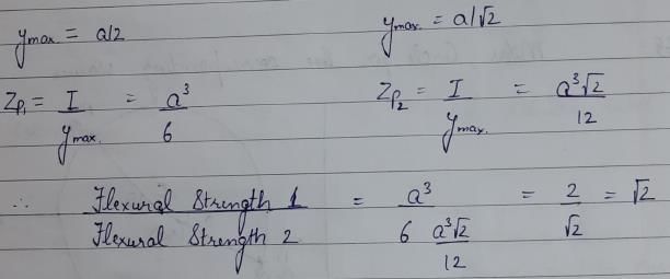
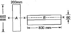
Cross-sections of two beams A (600 mm x 200mm) and B (800 mm x 60 mm) are shown in the figure given above. Both the beams have the same material. By how many times is the beam A stronger than the beam B in resisting bending
- a)80
- b)60
- c)50
- d)25
Correct answer is option 'D'. Can you explain this answer?
Cross-sections of two beams A (600 mm x 200mm) and B (800 mm x 60 mm) are shown in the figure given above. Both the beams have the same material. By how many times is the beam A stronger than the beam B in resisting bending
a)
80
b)
60
c)
50
d)
25
|
|
Varun Mukherjee answered |
Z = I/(y(max)) = bd2 /6
Za = (200) (600)2 / 6
Zb = (800) (600)2/6
Za / Zb = 25
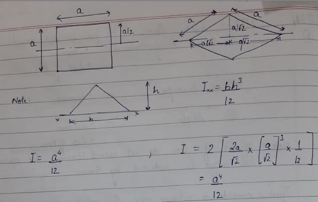
A beam of square cross -section ( S x B) is used as a beam with one diagonal horizontal. The location of the maximum shear stress from the neutral axis will be at distance o- a)zero
- b)B/4
- c)

- d)B/8
Correct answer is option 'C'. Can you explain this answer?
A beam of square cross -section ( S x B) is used as a beam with one diagonal horizontal. The location of the maximum shear stress from the neutral axis will be at distance o
a)
zero
b)
B/4
c)
d)
B/8
|
|
Pankaj Kapoor answered |
The digonal is  The location of maximum shear stress from neutral axis is at a distance of 1/8 length of diagonal i.e
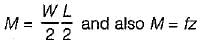
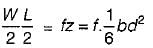
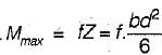
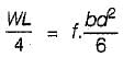
The location of maximum shear stress from neutral axis is at a distance of 1/8 length of diagonal i.e A simply supported beam of span L carries a concentrated load W at its mid-span. If the width b of the beam is constant and its depth is varying throughout the span, then what should be its mid-span depth, when design stress is f?- a)

- b)

- c)

- d)

Correct answer is option 'C'. Can you explain this answer?
A simply supported beam of span L carries a concentrated load W at its mid-span. If the width b of the beam is constant and its depth is varying throughout the span, then what should be its mid-span depth, when design stress is f?
a)
b)
c)
d)
|
|
Ashwin Desai answered |
Let mid span depth is d. Then BM at a distance L/2 from one end.
∴
∴
∴
or
∴
∴
∴
or
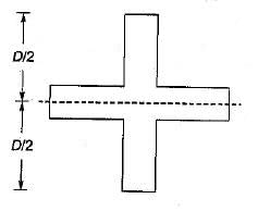
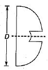
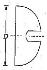
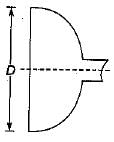
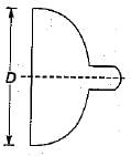
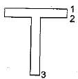
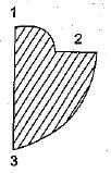
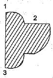
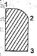
The modular ratio of the materials used in the flitched beam is 10 and the ratio of the allowable stresses is also 10. Four different sections of the beam are: shown in the given figures. The material shown hatched has larger modulus of elasticity and allowable stress than the rest.
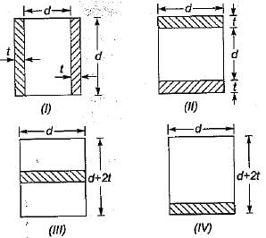 Which one of the following statements is true for the beam under consideration ?
- a)All the given sections would support the same magnitude of load.
- b)Sections’ll, III and IV would support equal loads which is more than what section I would support
- c)Sections I and II would support equal loads which is more than what section III and IV would support.
- d)Section II would support greatest load.
Correct answer is option 'D'. Can you explain this answer?
The modular ratio of the materials used in the flitched beam is 10 and the ratio of the allowable stresses is also 10. Four different sections of the beam are: shown in the given figures. The material shown hatched has larger modulus of elasticity and allowable stress than the rest.
Which one of the following statements is true for the beam under consideration ?
a)
All the given sections would support the same magnitude of load.
b)
Sections’ll, III and IV would support equal loads which is more than what section I would support
c)
Sections I and II would support equal loads which is more than what section III and IV would support.
d)
Section II would support greatest load.
|
|
Sreemoyee Deshpande answered |
In the flitched beams there are two principles to be followed in analysis,
(i) strain diagram is linear
(ii) The radius of curvature of both materials is same at all the points.
(i) strain diagram is linear
(ii) The radius of curvature of both materials is same at all the points.
- Allowable stress in weak material = f
- Allowable stress in strong material = 10 f
- Modulus of elasticity of weak material = E
- Modulus of elasticity of strong material = 10E
- Maximum strain in weak material = f/E
- Maximum strain in strong material =10f/10E = f/E
- The hatched material can be replaced by equivalent weak material when its width is multiplied by modular ratio. So the equivalent sections are:
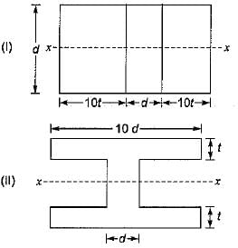
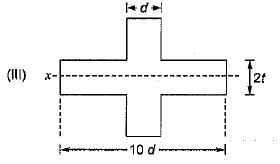
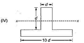
It is very clear that section modulus of section-ll is more than that of section-Ill as more area is close to the neutral axis in section-lI. Section-IV is unequal and its section modulus in tension and compression will be different. Since the strain is (f/E) at topmost and at bottom most fibre it is less than f/E.
So its capacity will be less than that of section-ll. Comparing section-l and section-ll, more area is away from the neutral axis in section-ll, so the moment capacity of section-ll is more than that of section-l. Thus section-ll has higher capacity.


A l-section is subjected to transverse shear force. At which layer maximum shear stress is developed?- a)Neutral axis
- b)At top edge of flange
- c)At bottom edge of fiange
- d)None of these
Correct answer is option 'A'. Can you explain this answer?
A l-section is subjected to transverse shear force. At which layer maximum shear stress is developed?
a)
Neutral axis
b)
At top edge of flange
c)
At bottom edge of fiange
d)
None of these

|
Bijoy Mehra answered |
Introduction:
In structural engineering, an L-section is a type of beam cross-section that resembles the shape of the letter 'L'. When an L-section beam is subjected to a transverse shear force, the shear stress distribution across the section can be analyzed. The question asks about the layer in the L-section where the maximum shear stress is developed.
Understanding Shear Stress:
Shear stress is a measure of the force per unit area acting parallel to the surface of a material. In the case of an L-section beam, the shear stress distribution can be visualized as a shear flow across the section.
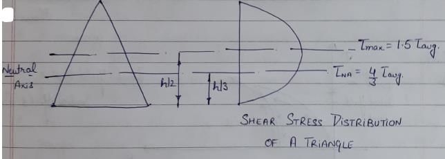
Shear Stress Distribution:
When a transverse shear force is applied to an L-section beam, the shear stress distribution is triangular in shape. The shear stress is maximum at the neutral axis of the section and decreases linearly towards the top and bottom edges of the flange.
Explanation:
The neutral axis is the axis in the L-section beam where there is no tension or compression. It is the location where the bending stress is zero. In an L-section beam, the neutral axis is located at the centroid of the section.
Since shear stress is directly related to the bending stress, the shear stress distribution follows a similar pattern as the bending stress distribution. Therefore, the maximum shear stress is developed at the neutral axis of the L-section beam.
At the top edge of the flange, the shear stress is lower than at the neutral axis because the distance from the neutral axis is greater. Similarly, at the bottom edge of the flange, the shear stress is also lower than at the neutral axis due to the larger distance from the neutral axis.
Conclusion:
In an L-section beam subjected to a transverse shear force, the maximum shear stress is developed at the neutral axis of the section. This is because the neutral axis is the location where the bending stress is zero, and shear stress distribution follows a similar pattern as the bending stress distribution.
In structural engineering, an L-section is a type of beam cross-section that resembles the shape of the letter 'L'. When an L-section beam is subjected to a transverse shear force, the shear stress distribution across the section can be analyzed. The question asks about the layer in the L-section where the maximum shear stress is developed.
Understanding Shear Stress:
Shear stress is a measure of the force per unit area acting parallel to the surface of a material. In the case of an L-section beam, the shear stress distribution can be visualized as a shear flow across the section.
Shear Stress Distribution:
When a transverse shear force is applied to an L-section beam, the shear stress distribution is triangular in shape. The shear stress is maximum at the neutral axis of the section and decreases linearly towards the top and bottom edges of the flange.
Explanation:
The neutral axis is the axis in the L-section beam where there is no tension or compression. It is the location where the bending stress is zero. In an L-section beam, the neutral axis is located at the centroid of the section.
Since shear stress is directly related to the bending stress, the shear stress distribution follows a similar pattern as the bending stress distribution. Therefore, the maximum shear stress is developed at the neutral axis of the L-section beam.
At the top edge of the flange, the shear stress is lower than at the neutral axis because the distance from the neutral axis is greater. Similarly, at the bottom edge of the flange, the shear stress is also lower than at the neutral axis due to the larger distance from the neutral axis.
Conclusion:
In an L-section beam subjected to a transverse shear force, the maximum shear stress is developed at the neutral axis of the section. This is because the neutral axis is the location where the bending stress is zero, and shear stress distribution follows a similar pattern as the bending stress distribution.

Chapter doubts & questions for Bending & Shear Stress in Beams - Solid Mechanics 2025 is part of Mechanical Engineering exam preparation. The chapters have been prepared according to the Mechanical Engineering exam syllabus. The Chapter doubts & questions, notes, tests & MCQs are made for Mechanical Engineering 2025 Exam. Find important definitions, questions, notes, meanings, examples, exercises, MCQs and online tests here.
Chapter doubts & questions of Bending & Shear Stress in Beams - Solid Mechanics in English & Hindi are available as part of Mechanical Engineering exam.
Download more important topics, notes, lectures and mock test series for Mechanical Engineering Exam by signing up for free.
Solid Mechanics
35 videos|74 docs|30 tests
|
|
© EduRev
|
Education Revolution
|


|


Signup to see your scores
go up
within 7 days!
within 7 days!
Takes less than 10 seconds to signup