


All Exams >
Electrical Engineering (EE) >
Control Systems >
All Questions
All questions of Controllers & Compensators for Electrical Engineering (EE) Exam
In the phase lead compensation network, the phase of ______ leads the phase of ______.- a)input voltage, output voltage
- b)input voltage, input voltage
- c)output voltage, input voltage
- d)output voltage, output voltage
Correct answer is option 'C'. Can you explain this answer?
In the phase lead compensation network, the phase of ______ leads the phase of ______.
a)
input voltage, output voltage
b)
input voltage, input voltage
c)
output voltage, input voltage
d)
output voltage, output voltage

|
Machine Experts answered |
Lead compensator:
Transfer function:
Transfer function:
If it is in the form of  then a < 1
then a < 1If it is in the form of  then a > b
In the frequency domain,

Phase angle, ∠G (jω) = tan−1ωαT − tan−1ωT
then a > bIn the frequency domain,
Phase angle, ∠G (jω) = tan−1ωαT − tan−1ωT
ϕ = tan-1 ωaT – tan-1 ωT
As a > 1 always (from the definition), ϕ is positive
Hence, it is clear that the phase of output voltage leads the phase of the input voltage.
As a > 1 always (from the definition), ϕ is positive
Hence, it is clear that the phase of output voltage leads the phase of the input voltage.

Direction: The following item consists of two statements, one labelled as ‘Statement (I)’ and the other as ‘Statement (II)’. Examine these two statements carefully and select the answers to these items using the code given below:Statement I: For type-II or higher systems, lead compensator may be used.
Statement II: Lead compensator increases the margin of stability.- a)Both Statement I and Statement II are individually true and Statement II is the correct explanation of Statement I
- b)Both Statement I and Statement II are individually true but Statement II is not the correct explanation of Statement I
- c)Statement I is true but Statement II is false
- d)Statement I is false but Statement II is true
Correct answer is option 'A'. Can you explain this answer?
Direction: The following item consists of two statements, one labelled as ‘Statement (I)’ and the other as ‘Statement (II)’. Examine these two statements carefully and select the answers to these items using the code given below:
Statement I: For type-II or higher systems, lead compensator may be used.
Statement II: Lead compensator increases the margin of stability.
Statement II: Lead compensator increases the margin of stability.
a)
Both Statement I and Statement II are individually true and Statement II is the correct explanation of Statement I
b)
Both Statement I and Statement II are individually true but Statement II is not the correct explanation of Statement I
c)
Statement I is true but Statement II is false
d)
Statement I is false but Statement II is true

|
Pioneer Academy answered |
In general, there are two situations in which compensation is required.
- In the first case, the system is absolutely unstable, and the compensation is required to stabilize it as well as to achieve a specified performance.
- In the second case, the system is stable, but the compensation is required to obtain the desired performance.
The systems which are of type-2 or higher are usually absolutely unstable. For type-2 or higher systems, only the lead compensator is required because only the lead compensator improves the margin of stability.
Both Statement I and Statement II are individually true and Statement II is the correct explanation of Statement I
Note: In type-1 and type-0 systems, stable operation is always possible if the gain is sufficiently reduced. In such cases, any of the three compensators, lead, lag, lag-lead may be used to obtain the desired performance.
The compensator required to improve the steady state response of a system is- a)Lag
- b)Lead
- c)Lag-lead
- d)Zero
Correct answer is option 'A'. Can you explain this answer?
The compensator required to improve the steady state response of a system is
a)
Lag
b)
Lead
c)
Lag-lead
d)
Zero
|
|
Ravi Singh answered |
Lag compensator:
Transfer function:
Transfer function:
If it is in the form of  then a < 1
then a < 1If it is in the form of  then a > b
Maximum phase lag frequency:
ωm = 1√Ta
Maximum phase lag::
then a > bMaximum phase lag frequency:
ωm = 1√Ta
Maximum phase lag::

ϕm is negative
Pole zero plot:

The pole is nearer to the origin.
Filter: It is a low pass filter (LPF)
Effect on the system:
Filter: It is a low pass filter (LPF)
Effect on the system:
- Rise time and settling time increases and Bandwidth decreases
- The transient response becomes slower
- The steady-state response is improved
- Stability decreases


Which of the following is not correct with respect to a phase-lead compensation network?- a)It increases system bandwidth
- b)It increases gain at higher frequencies
- c)It is used when fast transient response is required
- d)It is used when decrease rapidly near crossover frequency
Correct answer is option 'D'. Can you explain this answer?
Which of the following is not correct with respect to a phase-lead compensation network?
a)
It increases system bandwidth
b)
It increases gain at higher frequencies
c)
It is used when fast transient response is required
d)
It is used when decrease rapidly near crossover frequency
|
|
Shivam Das answered |
Understanding Phase-Lead Compensation
Phase-lead compensation is a technique used in control systems to improve stability and performance. Let's analyze why option 'D' is incorrect.
Key Characteristics of Phase-Lead Compensation:
- Increases System Bandwidth:
- Phase-lead compensation increases the bandwidth of the system. This allows the system to respond more quickly to changes in input.
- Increases Gain at Higher Frequencies:
- It provides an increase in gain at higher frequencies, which enhances the system's ability to track fast changes in input signals.
- Fast Transient Response:
- This compensation technique is particularly beneficial when fast transient responses are desired. It reduces the settling time and improves the overall responsiveness of the system.
Why Option 'D' is Incorrect:
- Decrease Rapidly Near Crossover Frequency:
- This statement is misleading. In a phase-lead compensation network, the phase margin is increased, and the gain does not decrease rapidly near the crossover frequency. Instead, the network is designed to maintain or even enhance the gain within the crossover region, leading to a more stable and responsive system.
Conclusion:
In summary, phase-lead compensation is characterized by its ability to enhance system performance. It does not lead to a rapid decrease in gain near the crossover frequency, making option 'D' the incorrect statement.
The transfer function of a PID controller is given by as ω tends to zero
- a)Magnitude of G(jω) tends to zero and phase angle of G(jω) tends to infinity
- b)Magnitude of G(jω) tends to infinity and phase angle of G(jω) tends to zero
- c)Magnitude of G(jω) tends to infinity and phase angle of G(jω) tends to +90°
- d)Magnitude of G(jω) tends to zero and phase angle of G(jω) tends to +90°
Correct answer is option 'C'. Can you explain this answer?
The transfer function of a PID controller is given byas ω tends to zero
as ω tends to zeroa)
Magnitude of G(jω) tends to zero and phase angle of G(jω) tends to infinity
b)
Magnitude of G(jω) tends to infinity and phase angle of G(jω) tends to zero
c)
Magnitude of G(jω) tends to infinity and phase angle of G(jω) tends to +90°
d)
Magnitude of G(jω) tends to zero and phase angle of G(jω) tends to +90°
|
|
Zoya Sharma answered |


Which of the following is a correct statement?- a)PI controllers improves steady state response
- b)PD controllers improves transient response
- c)Both (a) & (b)
- d)None of these
Correct answer is option 'C'. Can you explain this answer?
Which of the following is a correct statement?
a)
PI controllers improves steady state response
b)
PD controllers improves transient response
c)
Both (a) & (b)
d)
None of these
|
|
Pooja Patel answered |
Concept:
Proportional + Derivate(PD):

The additive combination of proportional & Derivative control is known as P-D control.
Proportional + Derivate(PD):
The additive combination of proportional & Derivative control is known as P-D control.
The overall transfer function for a PD controller is given by:

PD controller is nothing but a differentiator (or) a High Pass Filter.
PD controller is nothing but a differentiator (or) a High Pass Filter.
The frequency of noise is very high.
So this high pass filter will allow noise into the system which results in noise amplification.
PD Controllers reduce the response time and thus improve transient response
Effects of Proportional Derivative (PD) controllers:
- Decreases the type of the system by one
- Reduces the rise time and settling time
- It has high sensitivity.
- Rise time and settling time decreases and Bandwidth increases
- The speed of response is increased i.e. the transient response is improved
- Improves gain margin, phase margin, and resonant peak
- Increases the input noise
- Improves the stability
Proportional Integral Controller:
This controller resembles the combination of the proportional and integral controller.
The structure of this controller is shown below:

This is used to decrease the steady-state error without affecting the stability of the system.
The transfer function is defined as:

Analysis:
Analysis:
The transfer function of the system is calculated as:

Disadvantages: Slow reaction to the disturbances.
Disadvantages: Slow reaction to the disturbances.
Advantages:
- It provides the zero control error
- It is insensitive to the interference of the measurement channel.
- PI Controllers increase the type of the system and thus reduce steady-state error and improve steady state
response
Consider the following statements related to compensators used in control system applications:
1. When transient response is satisfactory and steady state characteristics are not satisfactory, normally lag compensation is employed.
2. Phase lag network is used to increase system stability and maintain velocity gain constant.
3. The capacitance is not used to fabricate a lag network.Which of these statements is/are correct?- a)1 and 3 only
- b)1, 2 and 3
- c)1 only
- d)1 and 2 only
Correct answer is option 'C'. Can you explain this answer?
Consider the following statements related to compensators used in control system applications:
1. When transient response is satisfactory and steady state characteristics are not satisfactory, normally lag compensation is employed.
2. Phase lag network is used to increase system stability and maintain velocity gain constant.
3. The capacitance is not used to fabricate a lag network.
1. When transient response is satisfactory and steady state characteristics are not satisfactory, normally lag compensation is employed.
2. Phase lag network is used to increase system stability and maintain velocity gain constant.
3. The capacitance is not used to fabricate a lag network.
Which of these statements is/are correct?
a)
1 and 3 only
b)
1, 2 and 3
c)
1 only
d)
1 and 2 only
|
|
Naveen Mukherjee answered |
Lag compensator is used to reduce steady-state error, therefore statement-1 is true.
As lag compensator reduces steady state error therefore, statement-2 is false.
Statement-3 is also false because capacitance is used to fabricate a lag network.
As lag compensator reduces steady state error therefore, statement-2 is false.
Statement-3 is also false because capacitance is used to fabricate a lag network.
An R-C network has the transfer function

The network could be used as
1. lead compensator
2. lag compensator
3. lag-lead compensator
Which of the above is/are correct?- a)1 only
- b)2 only
- c)3 only
- d)1, 2 and 3
Correct answer is option 'C'. Can you explain this answer?
An R-C network has the transfer function
The network could be used as
1. lead compensator
2. lag compensator
3. lag-lead compensator
Which of the above is/are correct?
The network could be used as
1. lead compensator
2. lag compensator
3. lag-lead compensator
Which of the above is/are correct?
a)
1 only
b)
2 only
c)
3 only
d)
1, 2 and 3
|
|
Ravi Singh answered |

Application:

Poles: s = -2, -8
Zeros: s = -4, -6
The pole-zero plot of the above transfer function is shown below.

The above pole-zero represents that the given system is a lag-lead compensator.
Phase lead compensation- a)increases bandwidth and increases steady-state error
- b)decreases bandwidth and decreases steady-state error
- c)will not affect bandwidth but decreases steady-state error
- d)increases bandwidth but will not affect steady-state error
Correct answer is option 'D'. Can you explain this answer?
Phase lead compensation
a)
increases bandwidth and increases steady-state error
b)
decreases bandwidth and decreases steady-state error
c)
will not affect bandwidth but decreases steady-state error
d)
increases bandwidth but will not affect steady-state error
|
|
Pooja Patel answered |
Lead compensator:
Transfer function:
Transfer function:
If it is in the form of  then a < 1
then a < 1If it is in the form of  then a > b
Maximum phase lag frequency: ωm = 1√Ta
Maximum phase lag::
then a > bMaximum phase lag frequency: ωm = 1√Ta
Maximum phase lag::
ϕm is positive
Pole zero plot:
The zero is nearer to the origin.
Filter: It is a high pass filter (HPF)
Effect on the system:
Filter: It is a high pass filter (HPF)
Effect on the system:
- Rise time and settling time decreases and Bandwidth increases
- The transient response becomes faster
- The steady-state response is not affected
- Improves the stability
- The velocity constant is usually increased
- Helps to increase the system error constant though to a limited extent
- The slope of the magnitude curve is reduced at the gain crossover frequency, as a result, relative stability improves
- The margin of stability of a system (phase margin) increased
PID controllers are tuned on the frequency response of the closed-loop system by- a)using the open-loop gain corresponding to marginal stability
- b)using the maximum amplitude of response
- c)using maximum value of phase
- d)using minimum value of phase
Correct answer is option 'A'. Can you explain this answer?
PID controllers are tuned on the frequency response of the closed-loop system by
a)
using the open-loop gain corresponding to marginal stability
b)
using the maximum amplitude of response
c)
using maximum value of phase
d)
using minimum value of phase
|
|
Aashna Dey answered |
Frequency Response of Closed-Loop System
The frequency response of a control system is the measurement of the system's response to a sinusoidal input signal at varying frequencies. It is an essential tool for analyzing the stability and performance of the closed-loop system.
A PID controller is a popular type of feedback controller that uses three terms: proportional, integral, and derivative, to control the system's output. It is necessary to tune the PID controller's parameters to achieve the desired performance and stability.
Tuning a PID Controller
There are various methods for tuning a PID controller, but the most common method is to use the frequency response of the closed-loop system. The following are the steps involved in tuning a PID controller:
1. Determine the Open-Loop Gain
The open-loop gain is the gain of the system when the feedback loop is opened. It is necessary to determine the open-loop gain of the system at the frequency corresponding to the marginal stability. The marginal stability is the frequency at which the system is just stable or unstable.
2. Calculate the Phase Margin
The phase margin is the amount of phase lag that the system can tolerate before becoming unstable. It is necessary to calculate the phase margin of the system at the frequency corresponding to the marginal stability.
3. Adjust the PID Parameters
The proportional, integral, and derivative parameters of the PID controller are adjusted based on the open-loop gain and phase margin. The proportional parameter is adjusted to achieve the desired response amplitude, the integral parameter is adjusted to eliminate the steady-state error, and the derivative parameter is adjusted to reduce the overshoot and settling time.
Why Option A is Correct?
The option A is correct because the open-loop gain corresponding to marginal stability is the most critical parameter for tuning a PID controller. The open-loop gain determines the system's gain margin, which is the amount of gain that the system can tolerate before becoming unstable. The gain margin is directly related to the stability and performance of the system. Therefore, tuning the PID controller based on the open-loop gain corresponding to marginal stability is the most effective method for achieving the desired performance and stability.
Which of the following statements is incorrect?- a)Lead compensator is used to reduce the settling time.
- b)Lag compensator is used to reduce the steady state error.
- c)Lead compensator may increase the order of a system.
- d)Lag compensator always stabilizes an unstable system.
Correct answer is option 'D'. Can you explain this answer?
Which of the following statements is incorrect?
a)
Lead compensator is used to reduce the settling time.
b)
Lag compensator is used to reduce the steady state error.
c)
Lead compensator may increase the order of a system.
d)
Lag compensator always stabilizes an unstable system.
|
|
Naveen Mukherjee answered |
The incorrect statement is option 'D' which states that "Lag compensator always stabilizes an unstable system."
Explanation:
A compensator is a control system component that is added to a system to improve its performance. Compensators are used to modify the transfer function of a system in order to achieve specific control objectives, such as reducing settling time, improving steady-state error, or stabilizing an unstable system.
Lag compensator:
A lag compensator is a type of compensator that is used to improve the steady-state response of a system. It introduces a pole at a frequency lower than the existing poles of the system. This results in a phase lag in the frequency response, which helps to reduce steady-state error. However, a lag compensator does not necessarily stabilize an unstable system. It can improve the performance of a stable system but cannot stabilize an inherently unstable system.
Lead compensator:
A lead compensator is a type of compensator that is used to improve the transient response of a system by reducing the settling time. It introduces a zero at a frequency higher than the existing poles of the system. This results in a phase lead in the frequency response, which helps to reduce the settling time. A lead compensator can increase the order of a system by introducing additional poles and zeros.
Stabilizing an unstable system:
Stabilizing an unstable system requires additional control techniques such as state feedback, pole placement, or observer-based control. A lag compensator alone cannot stabilize an unstable system. It can only improve the performance of a stable system by reducing steady-state error.
Conclusion:
In conclusion, the statement that "Lag compensator always stabilizes an unstable system" is incorrect. A lag compensator is used to reduce steady-state error but does not necessarily stabilize an unstable system. Stabilizing an unstable system requires additional control techniques.
Addition of zero at origin:- a)Improvement in transient response
- b)Reduction in steady state error
- c)Reduction is settling time
- d)Increase in damping constant
Correct answer is option 'A'. Can you explain this answer?
Addition of zero at origin:
a)
Improvement in transient response
b)
Reduction in steady state error
c)
Reduction is settling time
d)
Increase in damping constant

|
Devansh Banerjee answered |
Understanding the Addition of Zero at Origin
The addition of a zero at the origin in a control system has significant effects on the system's performance, particularly in transient response. Here’s a detailed explanation of why option 'A' is the correct answer.
1. Improvement in Transient Response
- The primary benefit of adding a zero at the origin is the enhancement of the transient response of the system.
- A zero at the origin introduces a phase lead, which helps in improving the system's ability to react to changes in input quickly.
- This phase lead reduces the rise time and improves the overshoot characteristics, leading to a faster settling time.
2. Impact on Steady-State Error
- While a zero at the origin can improve transient response, it doesn't directly impact the steady-state error.
- Steady-state error is primarily affected by the system's type (e.g., Type 0, Type 1, etc.) and the presence of poles at the origin, rather than zeros.
3. Reduction in Settling Time
- Although the transient response improves, the settling time may not necessarily decrease significantly due to other system dynamics.
- It’s essential to analyze the overall system response to determine the actual effect on settling time.
4. Damping Constant
- The addition of a zero does not directly increase the damping constant; instead, it creates a more oscillatory response.
- The damping characteristics depend on the overall pole-zero configuration and not solely on the addition of a zero at the origin.
In conclusion, adding a zero at the origin significantly improves the transient response by enhancing the system's speed of reaction to changes. However, it has little effect on steady-state error and damping characteristics, making option 'A' the correct choice.
Match the following :-

- a)1 - b, 2 - a, 3 - d, 4 - c
- b)1 - a, 2 - b, 3 - c, 4 - d
- c)1 - c, 2 - d, 3 - b, 4 - a
- d)1 - a, 2 - d, 3 - c, 4 - b
Correct answer is option 'A'. Can you explain this answer?
Match the following :-
a)
1 - b, 2 - a, 3 - d, 4 - c
b)
1 - a, 2 - b, 3 - c, 4 - d
c)
1 - c, 2 - d, 3 - b, 4 - a
d)
1 - a, 2 - d, 3 - c, 4 - b
|
|
Zoya Sharma answered |
Sink node:
- A local sink is a node of a directed graph with no exiting edges, also called a terminal.
- It is the output node in the signal flow graph. It is a node, which has only incoming branches.
Lag Compensator:
- Phase lag network offers high gain at low frequency.
- Thus, it performs the function of a low pass filter.
- The introduction of this network increases the steady-state performance of the system.

Damping Ratio:
- The damping ratio gives the level of damping in the control system related to critical damping.
- The damping ratio is defined as the ratio of actual damping to the critical damping of the system.
- It is the ratio of the damping coefficient of a differential equation of a system to the damping coefficient of critical damping.
- ζ = actual damping / critical damping
Cut-off rate: It is the slope of the log-magnitude curve near the cut-off region of the Bode-plot.
Which of the following can be the pole-zero configuration of a phase-lag controller (lag compensator)?- a)

- b)

- c)

- d)

Correct answer is option 'A'. Can you explain this answer?
Which of the following can be the pole-zero configuration of a phase-lag controller (lag compensator)?
a)
b)
c)
d)
|
|
Pooja Patel answered |
Let H(f) be TF of phase-lag controller


b < a
Pole is near to j ω axis than zero
The transfer function  represents a
- a)lag network
- b)lead network
- c)lag-lead network
- d)proportional controller
Correct answer is option 'A'. Can you explain this answer?
The transfer function represents a
represents aa)
lag network
b)
lead network
c)
lag-lead network
d)
proportional controller
|
|
Machine Experts answered |
Concept:
Lag compensator:
Transfer function:
If it is in the form of then a < 1
If it is in the form of then a > b
Maximum phase lag frequency:
ωm = 1/T√a
Maximum phase lag: ϕm = sin−1(α−1/α+1)
ϕm is negative
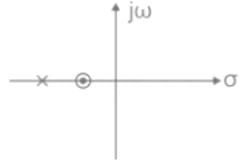
Pole zero plot:

The pole is nearer to the origin.
Given:

Zero = -2
Pole = -1
Analysis:
The pole-zero plot of T(s) is as shown:

Since the pole is closer to the origin than zero.
It is a lag compensator.
Lag compensator:
Transfer function:
If it is in the form of
then a < 1If it is in the form of
then a > bMaximum phase lag frequency:
ωm = 1/T√a
Maximum phase lag: ϕm = sin−1(α−1/α+1)
ϕm is negative
Pole zero plot:
The pole is nearer to the origin.
Given:
Zero = -2
Pole = -1
Analysis:
The pole-zero plot of T(s) is as shown:
Since the pole is closer to the origin than zero.
It is a lag compensator.
Consider the following statements regarding a control system:(a) Addition of pole to left half of s-plane reduce the relative stability(b) Addition of zero to left half of s-plane increase the damping factor(c) Integral controller reduces the steady state error(d) Derivate controller cannot be used in isolationWhich of the above statements are true?- a)(a) & (c) only
- b)(b) & (d) only
- c)(a), (b), (d) only
- d)All (a), (b), (c), (d)
Correct answer is option 'D'. Can you explain this answer?
Consider the following statements regarding a control system:
(a) Addition of pole to left half of s-plane reduce the relative stability
(b) Addition of zero to left half of s-plane increase the damping factor
(c) Integral controller reduces the steady state error
(d) Derivate controller cannot be used in isolation
Which of the above statements are true?
a)
(a) & (c) only
b)
(b) & (d) only
c)
(a), (b), (d) only
d)
All (a), (b), (c), (d)

|
Cstoppers Instructors answered |
(a) Addition of pole reduces stability
Consider system =
Adding Pole [say at origin]


(b) Addition of zero increase ξ
Consider system with Transfer function

Now add one zero to left half say at -2

(c) Integral controller adds one pole at origin
Now add one zero to left half say at -2
(c) Integral controller adds one pole at origin
As type of system increase steady state error reduce
(d) Derivative controllers are not used Alone because with sudden changes in the system the derivative controller will compensate the output fast therefore in long term effects the isolated controller will produce huge steady state errors.
The input of a controller is- a)Sensed signal
- b)Error signal
- c)Desired variable value
- d)Signal of fixed amplitude not dependent on desired variable value
Correct answer is option 'B'. Can you explain this answer?
The input of a controller is
a)
Sensed signal
b)
Error signal
c)
Desired variable value
d)
Signal of fixed amplitude not dependent on desired variable value
|
|
Zoya Sharma answered |
Controller is the block in the control system that control the input and provides the output and this is the first block of the system having the input as the error signal.
Lead compensation leads to:- a)Increases bandwidth
- b)Attenuation
- c)Increases damping factor
- d)Second order
Correct answer is option 'A'. Can you explain this answer?
Lead compensation leads to:
a)
Increases bandwidth
b)
Attenuation
c)
Increases damping factor
d)
Second order
|
|
Pallabi Pillai answered |
Lead compensation is a technique used in control systems to improve the performance of a system. It involves adding a lead compensator to the system to increase its bandwidth, which refers to the range of frequencies over which the system can effectively respond.
- Lead compensation increases the bandwidth of a system, allowing it to respond to a wider range of frequencies. This is because the lead compensator introduces a pole and a zero in the transfer function of the system, which results in a phase shift that enhances the system's frequency response.
- By increasing the bandwidth, lead compensation helps the system to respond more quickly to changes in the input signal. This can be particularly useful in applications where fast response times are required, such as in robotics or high-speed control systems.
- Lead compensation also helps to improve the stability of a system by increasing the damping factor. The damping factor is a measure of the system's ability to resist oscillations or overshoot in response to a disturbance. By increasing the damping factor, lead compensation reduces the likelihood of instability or oscillations in the system.
- Lead compensation is often used in second-order control systems, where the transfer function of the system has a second-order polynomial. In these systems, the lead compensator can be designed to introduce additional phase lead and increase the system's stability and performance.
In summary, lead compensation is a technique used in control systems to increase the bandwidth, improve stability, and enhance the performance of a system. By introducing a pole and a zero in the transfer function, lead compensation increases the system's frequency response and damping factor, leading to faster response times and improved stability.
The pole-zero plot shown below represents a

- a)Lag-lead compensating network
- b)PD controller
- c)PID controller
- d)None of the above
Correct answer is option 'A'. Can you explain this answer?
The pole-zero plot shown below represents a
a)
Lag-lead compensating network
b)
PD controller
c)
PID controller
d)
None of the above
|
|
Zoya Sharma answered |
Concept:
The speed of response and, the steady-state error can be simultaneously improved if both phase-lag and phase-lead compensation networks are used. However, instead of using two separate lag and lead networks, a single network combining both can be used.

The speed of response and, the steady-state error can be simultaneously improved if both phase-lag and phase-lead compensation networks are used. However, instead of using two separate lag and lead networks, a single network combining both can be used.
Lag-lead compensator:

In the lag-lead compensator network, the lag compensator is nearer to the origin.
In the lag-lead compensator network, the lag compensator is nearer to the origin.
Lead-lag compensator:

In the lead-lag compensator network, the lead compensator is nearer to the origin.
The Transfer Function of lead and lag compensators have _____ and ______ phase angles respectively which the system ______ and ______ respectively.- a)-ve, -ve, slower, faster
- b)+ve, +ve, slower, faster
- c)+ve, -ve, faster, slower
- d)-ve, +ve, faster, slower
Correct answer is option 'C'. Can you explain this answer?
The Transfer Function of lead and lag compensators have _____ and ______ phase angles respectively which the system ______ and ______ respectively.
a)
-ve, -ve, slower, faster
b)
+ve, +ve, slower, faster
c)
+ve, -ve, faster, slower
d)
-ve, +ve, faster, slower
|
|
Pooja Patel answered |
Concept:
We know:
Hc(s) = s+as+b;
when α = zero/pole = α/b is greater than 1 i.e., α > 1 then it is lag compensator.
else when α < 1, then it is lead compensator.
Calculation:
For lead compensator: Hc(s) = s+a/s+b

ϕ = tan−1(ω/1) − tan−1(ω/2)
i.e., phase angle will be positive for ω > 0
similarly, for lag compensator: Hc(s) = s+2/s+1

We know:
Hc(s) = s+as+b;
when α = zero/pole = α/b is greater than 1 i.e., α > 1 then it is lag compensator.
else when α < 1, then it is lead compensator.
Calculation:
For lead compensator: Hc(s) = s+a/s+b
ϕ = tan−1(ω/1) − tan−1(ω/2)
i.e., phase angle will be positive for ω > 0
similarly, for lag compensator: Hc(s) = s+2/s+1
ϕ = tan−1(ω/2) −tan−1(ω)
i.e. phase angle is negative for ω > 0.
Now,
For lead compensator, gain crossover frequency (ωgc) increase which causes an increase in B.W. and hence the speed of the system improves.
For lag compensator; Gain crossover frequency (ωpc) decreases which causes decreases in B.W. and hence speed of the system decreases.
Derivative output compensation:- a)Improvement in transient response
- b)Reduction in steady state error
- c)Reduction is settling time
- d)Increase in damping constant
Correct answer is option 'C'. Can you explain this answer?
Derivative output compensation:
a)
Improvement in transient response
b)
Reduction in steady state error
c)
Reduction is settling time
d)
Increase in damping constant
|
|
Pooja Patel answered |
Derivative controller is the controller that is also like high pass filter and is also phase lead controller and it is used to increase the speed of response of the system by increasing the damping coefficient.
For the network shown in the figure below, the frequency (in rad/s) at which the maximum phase lag occurs is, ___________.

Correct answer is between '0.30,0.33'. Can you explain this answer?
For the network shown in the figure below, the frequency (in rad/s) at which the maximum phase lag occurs is, ___________.
|
|
Pioneer Academy answered |
Given circuit is a lag compensator and transfer function is given as

On comparison we get, T = 1
βT = 10 ⇒ β = 10
The frequency at which maximum lead occurs is ωm = 1/T√β

On comparison we get, T = 1
βT = 10 ⇒ β = 10
The frequency at which maximum lead occurs is ωm = 1/T√β
The maximum phase shift that can be obtained by using a lead compensator with transfer function Gc(s) =  equal to
- a)15°
- b)30°
- c)45°
- d)60°
Correct answer is option 'B'. Can you explain this answer?
The maximum phase shift that can be obtained by using a lead compensator with transfer function Gc(s) = equal to
equal toa)
15°
b)
30°
c)
45°
d)
60°
|
|
Yash Patel answered |
The standard T/F of the compensator is

Maximum phase lead

Maximum phase lead frequency,
ωm = 1/T√a
Calculation:
The given transfer function is,
By comparing both transfer functions,
aT = 0.15
T = 0.05
a = 3
Maximum phase lead
Maximum phase lead
Maximum phase lead frequency,
ωm = 1/T√a
Calculation:
The given transfer function is,
By comparing both transfer functions,
aT = 0.15
T = 0.05
a = 3
Maximum phase lead

= sin-1 (0.5)
ϕm = 30°
A system with impulse response is essentially a _______ compensator and used as a ________ filter.- a)Integral, Comb
- b)Lead, high-pass
- c)Lag, low-pass
- d)Proportional, all pass
Correct answer is option 'C'. Can you explain this answer?
A system with impulse response is essentially a _______ compensator and used as a ________ filter.
a)
Integral, Comb
b)
Lead, high-pass
c)
Lag, low-pass
d)
Proportional, all pass
|
|
Yash Patel answered |
Lag compensator:
Transfer function:
Transfer function:
If it is in the form of  then a < 1
If it is in the form of then a > b
Maximum phase lag frequency: ωm = 1/T√α
Maximum phase lag: ϕm = sin−1(a−1/a+1)
ϕm is negative
then a < 1If it is in the form of
then a > bMaximum phase lag frequency: ωm = 1/T√α
Maximum phase lag: ϕm = sin−1(a−1/a+1)
ϕm is negative
Pole zero plot:

The pole is nearer to the origin.
Filter: It is a low pass filter (LPF)
Effect on the system:
Filter: It is a low pass filter (LPF)
Effect on the system:
- Rise time and settling time increases and Bandwidth decreases
- The transient response becomes slower
- The steady-state response is improved
- Stability decreases
If r = 1 in the G(s) =  then the compensator can give the minimum phase at a frequency of
- a)

- b)0.777 rad / s
- c)1 rad / s
- d)

Correct answer is option 'D'. Can you explain this answer?
If r = 1 in the G(s) = then the compensator can give the minimum phase at a frequency of
then the compensator can give the minimum phase at a frequency ofa)
b)
0.777 rad / s
c)
1 rad / s
d)
|
|
Machine Experts answered |
Concept:
Lead and Lag compensators:
Gc(s) = (1 + aTs) / (1 + Ts) where a and T > 0, a > 1 (lead) & a < 1 (lag)
∠Gc(s) = ϕ = tan-1 ωaT – tan-1 ωT
ωm is the geometric mean of the two corner frequencies 1/T and 1/aT
ωm = 1/T√α
Lead and Lag compensators:
Gc(s) = (1 + aTs) / (1 + Ts) where a and T > 0, a > 1 (lead) & a < 1 (lag)
∠Gc(s) = ϕ = tan-1 ωaT – tan-1 ωT
ωm is the geometric mean of the two corner frequencies 1/T and 1/aT
ωm = 1/T√α
Calculations:
Given Gc(s) =
r = 1
By substituting r value we get Gc(s) =
Here T = 1 and a = 0.1

Given Gc(s) =
r = 1
By substituting r value we get Gc(s) =
Here T = 1 and a = 0.1
If the transfer function of a compensator is represented as:
How much maximum phase shift can it add to the system?- a)20°
- b)45°
- c)30°
- d)60°
Correct answer is option 'C'. Can you explain this answer?
If the transfer function of a compensator is represented as:
How much maximum phase shift can it add to the system?
a)
20°
b)
45°
c)
30°
d)
60°
|
|
Machine Experts answered |
Concept:
The standard phase lead compensating network is given as:

The standard phase lead compensating network is given as:
Maximum phase Occurs at
ωm = 1/T√α
Maximum phase (ϕm)
sinϕm = 1−α/1+α
ωm = 1/T√α
Maximum phase (ϕm)
sinϕm = 1−α/1+α
Calculation:
Given:

a = 3 and T = 0.1
∵ a > 1
It is a Lead compensator.
Maximum phase lead is given as:

Given:
a = 3 and T = 0.1
∵ a > 1
It is a Lead compensator.
Maximum phase lead is given as:
A first order dynamic linear system with a proportional controller exhibits an offset to a unit step input. The offset can be reduced by- a)increasing the proportional gain
- b)adding derivative mode
- c)adding integral mode
- d)decreasing the porportional gain
Correct answer is option 'C'. Can you explain this answer?
A first order dynamic linear system with a proportional controller exhibits an offset to a unit step input. The offset can be reduced by
a)
increasing the proportional gain
b)
adding derivative mode
c)
adding integral mode
d)
decreasing the porportional gain
|
|
Kiran Iyer answered |
Introduction:
In a first-order dynamic linear system with a proportional controller, an offset is observed when a unit step input is applied. This offset refers to a steady-state error, where the output of the system does not reach the desired value. To reduce this offset, different control strategies can be employed. Among these strategies, adding an integral mode is the most effective method.
Explanation:
To understand why adding an integral mode can reduce the offset in a first-order dynamic linear system, let's first discuss the characteristics of the proportional controller.
1. Proportional Controller:
A proportional controller adjusts the output based on the error between the desired setpoint and the measured value. The control effort is proportional to this error, which means that the controller output is directly proportional to the error. However, a proportional controller alone cannot eliminate the steady-state error.
2. Offset in a First-Order System:
In a first-order system, the output response to a unit step input is characterized by a time constant and a gain. The time constant determines the speed at which the output approaches the final value, while the gain determines the magnitude of the output. However, due to the presence of a proportional controller, the output does not exactly reach the desired value, resulting in an offset or steady-state error.
3. Integral Mode:
Adding an integral mode to the control system allows the controller to integrate the error over time. This means that the control effort is not only based on the instantaneous error but also on the accumulated error over time. As a result, the integral mode can eliminate the steady-state error and bring the output closer to the desired setpoint.
4. Effect of Integral Mode:
When the integral mode is added to the proportional controller, the integrated error drives the controller output. As the error persists, the integral term continuously increases, leading to a larger control effort. This increased control effort compensates for the offset in the system and brings the output closer to the desired value.
Conclusion:
In a first-order dynamic linear system with a proportional controller, the offset or steady-state error can be reduced by adding an integral mode. The integral mode allows the controller to accumulate and integrate the error over time, resulting in an increased control effort that compensates for the offset. This control strategy is effective in minimizing the steady-state error and improving the system's response to a unit step input.
The magnitude plot of a rational transfer function G(s) with real coefficients is shown below. Which of the following compensators has such a magnitude plot?

- a)Lead compensator
- b)Lag compensator
- c)Lag-Lead compensator
- d)None of the above
Correct answer is option 'C'. Can you explain this answer?
The magnitude plot of a rational transfer function G(s) with real coefficients is shown below. Which of the following compensators has such a magnitude plot?
a)
Lead compensator
b)
Lag compensator
c)
Lag-Lead compensator
d)
None of the above
|
|
Pioneer Academy answered |

A system employing proportional plus error rate control is shown in figure below.

The value of error rate control (Ke) and 2% settling time for a damping ratio of 0.5 are respectively- a)0.116 and 2.53 sec
- b)0.265 and 0.116 sec
- c)0.116 and 0.265 sec
- d)0.265 and 2.53 se
Correct answer is option 'A'. Can you explain this answer?
A system employing proportional plus error rate control is shown in figure below.
The value of error rate control (Ke) and 2% settling time for a damping ratio of 0.5 are respectively
The value of error rate control (Ke) and 2% settling time for a damping ratio of 0.5 are respectively
a)
0.116 and 2.53 sec
b)
0.265 and 0.116 sec
c)
0.116 and 0.265 sec
d)
0.265 and 2.53 se
|
|
Prisha Sen answered |
The forward path gain of the given system is:

∴ Characteristic equation is
1 + G(s)H(s) = 0
or

or, s2 + (2 + 10 Ke)s +10 = 0
Here,
ωn = √10 rad/s
and 2ξωn = (2 + 10Ke)
Given, ξ = 0.5
So, 2 x 0.5 x √10 = (2 + 10Ke)
or,

= 1.16/10 = 0.116
Also, 2% settling time

∴ Characteristic equation is
1 + G(s)H(s) = 0
or
or, s2 + (2 + 10 Ke)s +10 = 0
Here,
ωn = √10 rad/s
and 2ξωn = (2 + 10Ke)
Given, ξ = 0.5
So, 2 x 0.5 x √10 = (2 + 10Ke)
or,
= 1.16/10 = 0.116
Also, 2% settling time
Which of the following properties is/are not exhibited by a phase lead network?
1. The velocity constant is usually increased.
2. The slope of the magnitude curve is reduced at the gain cross over frequency.
3. The bandwidth is reduced.
4. The response becomes faster.- a)1, 2, 3 and 4 only
- b)2 and 3 only
- c)3 only
- d)1 only
Correct answer is option 'C'. Can you explain this answer?
Which of the following properties is/are not exhibited by a phase lead network?
1. The velocity constant is usually increased.
2. The slope of the magnitude curve is reduced at the gain cross over frequency.
3. The bandwidth is reduced.
4. The response becomes faster.
1. The velocity constant is usually increased.
2. The slope of the magnitude curve is reduced at the gain cross over frequency.
3. The bandwidth is reduced.
4. The response becomes faster.
a)
1, 2, 3 and 4 only
b)
2 and 3 only
c)
3 only
d)
1 only
|
|
Anoushka Choudhury answered |
Due to a phase lead network, bandwidth is increased. Hence, option (d) is correct.
Which of the following is NOT the disadvantage of lag compensator in a control system?- a)In lag compensator, the attenuation offered by it shifts the gain crossover frequency to a lower point, thereby decreasing the bandwidth.
- b)The lag network offers a reduction in bandwidth, and this gives shorter rise time and settling time and so the transient response.
- c)A lag compensator somewhat acts as a proportional plus integral controller, hence adversely affects the stability of the system.
- d)Though the system response is longer due to decreased bandwidth, the response is quite slow
Correct answer is option 'B'. Can you explain this answer?
Which of the following is NOT the disadvantage of lag compensator in a control system?
a)
In lag compensator, the attenuation offered by it shifts the gain crossover frequency to a lower point, thereby decreasing the bandwidth.
b)
The lag network offers a reduction in bandwidth, and this gives shorter rise time and settling time and so the transient response.
c)
A lag compensator somewhat acts as a proportional plus integral controller, hence adversely affects the stability of the system.
d)
Though the system response is longer due to decreased bandwidth, the response is quite slow
|
|
Zoya Sharma answered |
Advantages of Lag Compensator:
- A phase lag network offers high gain at low frequency. Thus, it performs the function of a low pass filter.
- The introduction of this network increases the steady-state performance of the system.
- The lag network offers a reduction in bandwidth and this provides longer rise time and settling time and so the transient response.
- The angular contribution of the pole is more than that of the compensator zero because the pole dominates the zero in the lag compensator.
Advantages of Lead Compensator:
- It improves the damping of the overall system.
- The enhanced damping of the system supports less overshoot along with less rise time and settling time. Therefore, the transient response gets improved.
- The addition of a lead network improves the phase margin.
- A system with a lead network provides a quick response as it increases bandwidth thereby providing a faster response.
- Lead networks do not disturb the steady-state error of the system.
- It maximizes the velocity constant of the system.
The action of a PD controller is to- a)increase the rise time and steady state error of the system.
- b)reduce the rise time and increase the steady error of the system.
- c)maintain a constant value of rise time and reduce the steady state error of the system.
- d)reduce the rise time and maintain a constant value of steady state error of the system.
Correct answer is option 'D'. Can you explain this answer?
The action of a PD controller is to
a)
increase the rise time and steady state error of the system.
b)
reduce the rise time and increase the steady error of the system.
c)
maintain a constant value of rise time and reduce the steady state error of the system.
d)
reduce the rise time and maintain a constant value of steady state error of the system.
|
|
Aniket Choudhury answered |
Due to PD controller, a zero is added to the forward path which results in a lead compensator. Therefore, steady state error remais the same whiie rise time of the system is reduced (i.e. stability is increased).
Given a badly underdamped control system, the type of cascade compensator to be used to improve its damping is- a)phase-lag
- b)phase-lead-lag
- c)phase-lead
- d)notch filter
Correct answer is option 'C'. Can you explain this answer?
Given a badly underdamped control system, the type of cascade compensator to be used to improve its damping is
a)
phase-lag
b)
phase-lead-lag
c)
phase-lead
d)
notch filter
|
|
Aniket Shah answered |
Improving Damping in a Badly Underdamped Control System
Underdamped control systems often exhibit oscillatory behavior, which can lead to instability and poor performance. To improve the damping of such a system, a cascade compensator can be used. Among the given options, the appropriate type of cascade compensator to be used is a phase-lead compensator.
The phase-lead compensator is designed to increase the phase margin of the system, which helps improve stability and damping. It achieves this by introducing a phase lead at the desired frequency range. The phase lead compensator consists of a high-pass filter and a gain element.
Below are the reasons why the phase-lead compensator is the correct choice in this scenario:
1. Phase Margin Improvement:
The phase-lead compensator increases the phase margin of the system. The phase margin is the amount by which the phase of the system lags behind -180 degrees at the gain crossover frequency. By increasing the phase margin, the system becomes more stable and better damped.
2. Introduction of Phase Lead:
The phase-lead compensator introduces a phase lead at the desired frequency range. This additional phase lead helps to counteract the phase lag caused by the poorly damped system. By adding a phase lead, the system's phase response is shifted in a way that improves damping and stability.
3. Frequency Response Shaping:
The phase-lead compensator also shapes the frequency response of the system. It allows for boosting the gain at certain frequencies while maintaining stability. This control over the frequency response helps to improve the overall performance of the system by reducing oscillations and overshoot.
4. Stability Enhancement:
By increasing the phase margin and introducing a phase lead, the phase-lead compensator enhances the stability of the system. It helps to suppress oscillations and prevent the system from becoming unstable. This is crucial in underdamped systems where the lack of damping can lead to erratic behavior and instability.
In summary, to improve the damping of a badly underdamped control system, a phase-lead compensator is the most suitable type of cascade compensator. It increases the phase margin, introduces a phase lead, shapes the frequency response, and enhances stability.
The transfer function C(s) of a compensator is given below.
 The frequency range in which the phase (lead) introduced by the compensator reaches the maximum is
- a)0.1 < ω < 1
- b)1 < ω < 10
- c)10 < ω < 100
- d)ω > 100
Correct answer is option 'A'. Can you explain this answer?
The transfer function C(s) of a compensator is given below.
The frequency range in which the phase (lead) introduced by the compensator reaches the maximum is
a)
0.1 < ω < 1
b)
1 < ω < 10
c)
10 < ω < 100
d)
ω > 100
|
|
Pooja Patel answered |

Pole zero diagram of the above transfer function is

It represents a standard lead lag compensator. For a lead lag compensator, maximum lead occurs at initial frequency.
So, maximum lead occurs at 0.1 < ω < 1.
Phase lead occurs at: - a) low frequency regions
- b)high frequency regions
- c)moderate frequencies
- d)very low frequency regions
Correct answer is option 'B'. Can you explain this answer?
Phase lead occurs at:
a)
low frequency regions
b)
high frequency regions
c)
moderate frequencies
d)
very low frequency regions
|
|
Sanvi Kapoor answered |
Phase lead occurs in phase lead compensator and it occurs at the high-frequency region.
Lead compensator:
Transfer function:
Transfer function:
If it is in the form of then a < 1
then a < 1If it is in the form of then a > b
Maximum phase lag frequency: ωm = 1√Ta
Maximum phase lag::
then a > bMaximum phase lag frequency: ωm = 1√Ta
Maximum phase lag::
ϕm is positive
Pole zero plot:
The zero is nearer to the origin.
Filter: It is a high pass filter (HPF)
Effect on the system:
Filter: It is a high pass filter (HPF)
Effect on the system:
- Rise time and settling time decreases and Bandwidth increases
- The transient response becomes faster
- The steady-state response is not affected
- Improves the stability
A phase lead compensation network- a)speeds up the dynamic response
- b)decreases the system bandwidth
- c)reduces the steady state error
- d)is applied when error constants are specified
Correct answer is option 'D'. Can you explain this answer?
A phase lead compensation network
a)
speeds up the dynamic response
b)
decreases the system bandwidth
c)
reduces the steady state error
d)
is applied when error constants are specified
|
|
Sarthak Sharma answered |
Phase Lead Compensation Network: Explanation of Answer D
Introduction:
Phase lead compensation is a type of frequency domain compensation technique used in control systems to stabilize the closed-loop system, increase its phase margin, and improve its transient response. A phase lead compensation network is a circuit that introduces a phase lead in the transfer function of the plant to improve its stability and performance.
Answer Explanation:
The correct answer is option D, which states that the phase lead compensation network is applied when error constants are specified.
Explanation:
Error constants are the steady-state errors of a control system, which indicate the difference between the desired output and the actual output of the system. The error constants are used to measure the accuracy and precision of the control system. The phase lead compensation network is used to reduce the steady-state error of the system, which means that the output of the system will be closer to the desired output. Therefore, the phase lead compensation network is applied when error constants are specified to achieve better accuracy and precision of the system.
Other Options:
Option A: Speeding up the dynamic response is the purpose of phase lag compensation, which introduces a phase lag in the transfer function of the plant to reduce the overshoot and the settling time of the system.
Option B: Decreasing the system bandwidth is the purpose of low-pass filters, which attenuate the high-frequency components of the input signal to reduce the noise and the distortion in the output signal.
Option C: Reducing the steady-state error is the purpose of integral compensation, which introduces an integrator in the transfer function of the plant to eliminate the steady-state error of the system.
Conclusion:
In conclusion, the phase lead compensation network is applied when error constants are specified to reduce the steady-state error of the control system. The other options are not correct because they describe different compensation techniques with different purposes.
Addition of zeros in a transfer function causes- a)lag compensator
- b)lead compensator
- c)lead-lag compensator
- d)none of the above
Correct answer is option 'B'. Can you explain this answer?
Addition of zeros in a transfer function causes
a)
lag compensator
b)
lead compensator
c)
lead-lag compensator
d)
none of the above
|
|
Bijoy Mehta answered |
Pole-zero plot for lead and lag compensators are shown below.

Since zero is close to origin in a lead compensator, therefore addition of zero in a transfer function will cause lead compensator.
Since zero is close to origin in a lead compensator, therefore addition of zero in a transfer function will cause lead compensator.
Which of the following is true for the network shown below -

- a)Lead compensator
- b)Lag compensator
- c)Lead-lag compensator
- d)None of the above
Correct answer is option 'A'. Can you explain this answer?
Which of the following is true for the network shown below -
a)
Lead compensator
b)
Lag compensator
c)
Lead-lag compensator
d)
None of the above
|
|
Yash Patel answered |
In general, the lead and lag compensator is represented by the below transfer function

If a > b then that is lag compensator because pole comes first.
If a < b then that is the lead compensator since zero comes first.
Analysis:
Lead compensator:
1) When sinusoidal input applied to this it produces sinusoidal output with the phase lead input.
2) It speeds up the Transient response and increases the margin for stability.
A circuit diagram is as shown:

Response is:

Lead constant α =

Derivative error compensation:- a)Improvement in transient response
- b)Reduction in steady state error
- c)Reduction is settling time
- d)Increase in damping constant
Correct answer is option 'D'. Can you explain this answer?
Derivative error compensation:
a)
Improvement in transient response
b)
Reduction in steady state error
c)
Reduction is settling time
d)
Increase in damping constant
|
|
Pooja Patel answered |
Damping constant reduces the gain, as it is inversely proportional to the gain and as increasing the damping gain reduces and hence the speed of response and bandwidth are both increased.
Lag-lead compensation is a:- a)Increases bandwidth
- b)Attenuation
- c)Increases damping factor
- d)Second order
Correct answer is option 'D'. Can you explain this answer?
Lag-lead compensation is a:
a)
Increases bandwidth
b)
Attenuation
c)
Increases damping factor
d)
Second order
|
|
Zoya Sharma answered |
Lag-Lead compensation is a second order control system which has lead and lag compensation both and thus has combined effect of both lead and lag compensation this is obtained by the differential equation.
Rate compensation:- a)Increases bandwidth
- b)Attenuation
- c)Increases damping factor
- d)Second order
Correct answer is option 'C'. Can you explain this answer?
Rate compensation:
a)
Increases bandwidth
b)
Attenuation
c)
Increases damping factor
d)
Second order
|
|
Zoya Sharma answered |
Damping factor is increased for reducing the oscillations and increasing the stability and speed of response which are the essential requirements of the control system and damping factor is increased by the rate compensation.
In the control system shown below, the controller which can give infinite value of steady-stae error to a ramp input is

- a)derivative plus proportional type
- b)derivative type
- c)proportional type
- d)both (a) and (b)
Correct answer is option 'D'. Can you explain this answer?
In the control system shown below, the controller which can give infinite value of steady-stae error to a ramp input is
a)
derivative plus proportional type
b)
derivative type
c)
proportional type
d)
both (a) and (b)
|
|
Rithika Pillai answered |
Case-1: For integral type

∴
∴ ess = Ti/2
Case-2: For derivative type

G(s)H(s) = (10sTd)/(s+5)
∴

∴ ess = 1/Kv = ∞
Case-3: For proportional type
G(s)H(s) = 10Kp/(s+5)
∴

∴
Case-4: For proportional plus derivative type

∴

∴ ess = 1/Kv = ∞
∴
∴ ess = Ti/2
Case-2: For derivative type
G(s)H(s) = (10sTd)/(s+5)
∴
∴ ess = 1/Kv = ∞
Case-3: For proportional type
G(s)H(s) = 10Kp/(s+5)
∴
∴
Case-4: For proportional plus derivative type
∴
∴ ess = 1/Kv = ∞
A compensator with the transfer function G(s) =  can give maximum gain of
- a)-20 dB
- b)-10 dB
- c)0 dB
- d)20 dB
Correct answer is option 'C'. Can you explain this answer?
A compensator with the transfer function G(s) = can give maximum gain of
can give maximum gain ofa)
-20 dB
b)
-10 dB
c)
0 dB
d)
20 dB
|
|
Pooja Patel answered |

For all ω Numerator is less than Denominator maximum value of |G(s)| occurs at ω = 0
|G(s)|max = 1
In dB, 20 log (1) = 0 dB
With regard to the filtering property, the lead compensator and the lag compensators are respectively- a)low pass and high pass filters
- b)high pass and low pass filters
- c)both high pass filters
- d)both low pass filters
Correct answer is option 'B'. Can you explain this answer?
With regard to the filtering property, the lead compensator and the lag compensators are respectively
a)
low pass and high pass filters
b)
high pass and low pass filters
c)
both high pass filters
d)
both low pass filters

|
Pankaj Rane answered |
Lead and Lag Compensators: Filtering Property
Lead and lag compensators are two types of frequency-domain compensators used in control systems to improve the stability and steady-state performance. Both of these compensators have a filtering property that allows them to modify the frequency response of the system. The filtering property of the lead and lag compensators is discussed below.
Lead Compensator: High Pass Filter
A lead compensator is a type of compensator that adds a pole and a zero to the open-loop transfer function of the system. The pole and zero are placed in such a way that the phase lag of the system is reduced, which increases the system's stability. The lead compensator also increases the bandwidth of the system, which improves the transient response.
The lead compensator acts as a high pass filter because it allows high-frequency signals to pass through while attenuating low-frequency signals. This is due to the fact that the pole and zero of the lead compensator are located at high frequencies. Therefore, the lead compensator is a high pass filter.
Lag Compensator: Low Pass Filter
A lag compensator is a type of compensator that adds a pole and a zero to the open-loop transfer function of the system. The pole and zero are placed in such a way that the phase lead of the system is increased, which reduces the steady-state error. The lag compensator also reduces the bandwidth of the system, which improves the noise rejection.
The lag compensator acts as a low pass filter because it allows low-frequency signals to pass through while attenuating high-frequency signals. This is due to the fact that the pole and zero of the lag compensator are located at low frequencies. Therefore, the lag compensator is a low pass filter.
Conclusion
In summary, the lead compensator acts as a high pass filter, while the lag compensator acts as a low pass filter. These filters modify the frequency response of the system and have a significant impact on the stability, transient response, and steady-state performance of the system. Therefore, it is important to choose the appropriate compensator based on the system's requirements.
For the following network to work as lag compensator, the value of R2 would be

- a)R2 ≥ 20 Ω
- b)R2 ≤ 10 Ω
- c)

- d)Any value of R2
Correct answer is option 'D'. Can you explain this answer?
For the following network to work as lag compensator, the value of R2 would be
a)
R2 ≥ 20 Ω
b)
R2 ≤ 10 Ω
c)
d)
Any value of R2
|
|
Pooja Patel answered |
Lead compensator:
Transfer function:
Transfer function:
If it is in the form of then a < 1
then a < 1If it is in the form of then a > b
Maximum phase lag frequency: ωm = 1√Ta
Maximum phase lag::
then a > bMaximum phase lag frequency: ωm = 1√Ta
Maximum phase lag::
ϕm is positive
Pole zero plot:

The pole is nearer to the origin.
Filter: It is a low pass filter (LPF)
Effect on the system:
The pole is nearer to the origin.
Filter: It is a low pass filter (LPF)
Effect on the system:
- Rise time and settling time increases and Bandwidth decreases
- The transient response becomes slower
- The steady-state response is improved
- Stability decreases
Application:
The equivalent Laplace transform network for the given network is,

The equivalent Laplace transform network for the given network is,
By applying voltage division,
 The above system to be lag compensator, β > 1
The above system to be lag compensator, β > 1
⇒ R1 > 0
Therefore, at any value of R2 the given system acts as lag compensator.
Phase lag controller:- a)Improvement in transient response
- b)Reduction in steady state error
- c)Reduction is settling time
- d)Increase in damping constant
Correct answer is option 'B'. Can you explain this answer?
Phase lag controller:
a)
Improvement in transient response
b)
Reduction in steady state error
c)
Reduction is settling time
d)
Increase in damping constant
|
|
Zoya Sharma answered |
Phase lag controller is the integral controller that creates the phase lag and does not affect the value of the damping factor and that tries to reduce the steady state error.
The block diagram of an integral control is shown in figure below.

The steady state error in the above system for a parabolic input is- a)

- b)

- c)zero
- d)

Correct answer is option 'D'. Can you explain this answer?
The block diagram of an integral control is shown in figure below.
The steady state error in the above system for a parabolic input is
The steady state error in the above system for a parabolic input is
a)
b)
c)
zero
d)
|
|
Anoushka Choudhury answered |
For the given system, forward path transfer function is

For parabolic input, steady state error is

where,


∴
For parabolic input, steady state error is
where,
∴
Integral feedback control- a)reduces feedback time
- b)improves transient response
- c)improves steady state response
- d)none of the above
Correct answer is option 'C'. Can you explain this answer?
Integral feedback control
a)
reduces feedback time
b)
improves transient response
c)
improves steady state response
d)
none of the above
|
|
Ankita Das answered |
Integral Feedback Control Explained
Integral feedback control is a crucial component in control systems, particularly in applications requiring precise output regulation. It primarily enhances the steady-state response of a system, making it an essential concept in Electrical Engineering.
Key Features of Integral Feedback Control
- **Elimination of Steady-State Error**:
Integral control acts on the accumulated error over time. By integrating the error signal, it ensures that any persistent offset from the desired setpoint is corrected, effectively driving the steady-state error to zero.
- **Continuous Adjustment**:
The integral term continuously adjusts the control output as long as there is an error, which results in improved accuracy and performance over time.
Impact on System Performance
- **Steady-State Response**:
The primary benefit of integral feedback is the improvement in steady-state performance. Systems with integral control can achieve a stable output that matches the desired value with minimal or no error.
- **Transient Response Considerations**:
While integral control can enhance steady-state accuracy, it may lead to slower transient responses or overshoot if not properly tuned. Thus, while it improves steady-state response, careful tuning is essential to manage the transient behavior.
Conclusion
In summary, integral feedback control is primarily used to enhance the steady-state response of control systems. By eliminating steady-state errors through continuous adjustment of the control output, it ensures that the system remains closely aligned with the desired setpoint over time. Effective implementation requires careful tuning to balance the benefits against potential impacts on transient response.
Assertion (A): Introduction of phase lag network in forward path increases the phase shift.
Reason (R): A phase lag network has pole nearer to the imaginary axis as compared to zero.- a)Both A and R are true and R is a correct explanation of A.
- b)Both A and R are true but R is not a correct explanation of A.
- c)A is true but R is false.
- d)A is false but R is true.
Correct answer is option 'D'. Can you explain this answer?
Assertion (A): Introduction of phase lag network in forward path increases the phase shift.
Reason (R): A phase lag network has pole nearer to the imaginary axis as compared to zero.
Reason (R): A phase lag network has pole nearer to the imaginary axis as compared to zero.
a)
Both A and R are true and R is a correct explanation of A.
b)
Both A and R are true but R is not a correct explanation of A.
c)
A is true but R is false.
d)
A is false but R is true.
|
|
Anoushka Kumar answered |
The transfer function of a phase-lag network is:

The pole-zero plot is shown below:

Here, pole is nearer to the imaginary axis and origin compared to zero.
Hence, reason (R) is true.
Introduction of phase lag network in forward path reduces the phase shift. Hence, assertion (A) is a false statement.
The pole-zero plot is shown below:
Here, pole is nearer to the imaginary axis and origin compared to zero.
Hence, reason (R) is true.
Introduction of phase lag network in forward path reduces the phase shift. Hence, assertion (A) is a false statement.
Chapter doubts & questions for Controllers & Compensators - Control Systems 2025 is part of Electrical Engineering (EE) exam preparation. The chapters have been prepared according to the Electrical Engineering (EE) exam syllabus. The Chapter doubts & questions, notes, tests & MCQs are made for Electrical Engineering (EE) 2025 Exam. Find important definitions, questions, notes, meanings, examples, exercises, MCQs and online tests here.
Chapter doubts & questions of Controllers & Compensators - Control Systems in English & Hindi are available as part of Electrical Engineering (EE) exam.
Download more important topics, notes, lectures and mock test series for Electrical Engineering (EE) Exam by signing up for free.
Control Systems
54 videos|83 docs|40 tests
|

Signup to see your scores go up within 7 days!
Study with 1000+ FREE Docs, Videos & Tests
10M+ students study on EduRev
|
© EduRev
|
Education Revolution
|


|


Signup on EduRev and stay on top of your study goals
10M+ students crushing their study goals daily