


All Exams >
Electronics and Communication Engineering (ECE) >
Digital Circuits >
All Questions
All questions of Data Selectors & Multiplexers for Electronics and Communication Engineering (ECE) Exam
One multiplexer can take the place of ___________- a)Several SSI logic gates
- b)Combinational logic circuits
- c)Several Ex-NOR gates
- d)Several SSI logic gates or combinational logic circuits
Correct answer is option 'D'. Can you explain this answer?
One multiplexer can take the place of ___________
a)
Several SSI logic gates
b)
Combinational logic circuits
c)
Several Ex-NOR gates
d)
Several SSI logic gates or combinational logic circuits
|
|
Kunal Yadav answered |
Explanation:
A multiplexer, also known as a data selector, is a combinational logic circuit that can select one of several input signals and route it to a single output line. It is often used to implement logic functions or to enable the transfer of data from multiple sources to a single destination.
1. Multiplexer as a replacement for several SSI logic gates:
- SSI (Small Scale Integration) logic gates are basic logic gates like AND, OR, NOT, etc., which are typically implemented using discrete components.
- A multiplexer can perform the same logic functions as these gates by properly selecting its inputs and control lines.
- For example, a multiplexer with 2 input lines and 1 output line can replace an AND gate, while a multiplexer with 2 input lines, 1 output line, and an inverted control line can replace a NOT gate.
- By using different combinations of inputs and control lines, a multiplexer can replace several SSI logic gates.
2. Multiplexer as a replacement for combinational logic circuits:
- Combinational logic circuits are built using basic logic gates, flip-flops, and other combinational building blocks.
- These circuits perform complex logic functions by combining the outputs of multiple gates.
- A multiplexer can emulate the behavior of a combinational logic circuit by connecting its inputs to the outputs of the gates in the circuit and using its control lines to properly route the signals.
- By configuring the multiplexer appropriately, it can perform the same logic function as the combinational circuit.
3. Multiplexer as a replacement for several Ex-NOR gates:
- Ex-NOR gates are logic gates that produce a high output only when the number of high inputs is even.
- A multiplexer can replace Ex-NOR gates by selecting its inputs and control lines in a way that matches the truth table of the Ex-NOR gate.
- By connecting the inputs of the Ex-NOR gate to the input lines of the multiplexer and using the control lines to select the appropriate input combination, the multiplexer can produce the same output as the Ex-NOR gate.
Conclusion:
- A multiplexer can replace several SSI logic gates or combinational logic circuits by carefully selecting its inputs and control lines to perform the required logic function.
- This makes multiplexers versatile components that can simplify circuit design and reduce the number of components needed.

A digital multiplexer is a combinational circuit that selects ___________- a)One digital information from several sources and transmits the selected one
- b)Many digital information and convert them into one
- c)Many decimal inputs and transmits the selected information
- d)Many decimal outputs and accepts the selected information
Correct answer is option 'A'. Can you explain this answer?
A digital multiplexer is a combinational circuit that selects ___________
a)
One digital information from several sources and transmits the selected one
b)
Many digital information and convert them into one
c)
Many decimal inputs and transmits the selected information
d)
Many decimal outputs and accepts the selected information
|
|
Sanjana Iyer answered |
Digital Multiplexer:
A digital multiplexer is a combinational circuit that selects one digital information from several sources and transmits the selected one. It has several input lines, one output line, and a select line. The select line determines which input line is transmitted to the output line.
Working of Digital Multiplexer:
The working of the digital multiplexer can be explained as follows:
- The digital multiplexer has several input lines and one output line. The input lines are labelled as I0, I1, I2, … In-1 and the output line is labelled as Y.
- The digital multiplexer also has a select line labelled as S.
- The number of input lines is defined by the number of select lines, which is given by 2n, where n is the number of select lines.
- Depending on the value of the select line, the corresponding input line is transmitted to the output line.
- The output line can be represented as Y = S.I0 + S'.I1, where S' is the complement of S.
- The truth table of the digital multiplexer is given below:
S | I0 | I1 | I2 | I3 | Y
--|----|----|----|----|--
0 | 0 | 0 | 0 | 0 | 0
0 | 1 | 0 | 0 | 0 | 1
0 | 0 | 1 | 0 | 0 | 1
0 | 1 | 1 | 0 | 0 | 1
0 | 0 | 0 | 1 | 0 | 1
0 | 1 | 0 | 1 | 0 | 1
0 | 0 | 1 | 1 | 0 | 1
0 | 1 | 1 | 1 | 0 | 1
1 | 0 | 0 | 0 | 0 | 0
1 | 0 | 1 | 0 | 0 | 0
1 | 0 | 0 | 1 | 0 | 0
1 | 0 | 1 | 1 | 0 | 0
1 | 1 | 0 | 0 | 1 | 1
1 | 1 | 1 | 0 | 1 | 1
1 | 1 | 0 | 1 | 1 | 1
1 | 1 | 1 | 1 | 1 | 1
Uses of Digital Multiplexer:
The digital multiplexer is used in various applications such as:
- Digital communication systems
- Digital signal processing
- Computer memory systems
- Microprocessors and microcontrollers
- Digital audio and video systems
Conclusion:
Thus, a digital multiplexer is a combinational circuit that selects one digital information from several sources and transmits the selected one. It has several input lines, one output line, and a select line. The select line determines which input line is transmitted to the output line. The digital multiplexer is used
Which is the major functioning responsibility of the multiplexing combinational circuit?- a)Decoding the binary information
- b)Generation of all minterms in an output function with OR-gate
- c)Generation of selected path between multiple sources and a single destination
- d)Encoding of binary information
Correct answer is option 'C'. Can you explain this answer?
Which is the major functioning responsibility of the multiplexing combinational circuit?
a)
Decoding the binary information
b)
Generation of all minterms in an output function with OR-gate
c)
Generation of selected path between multiple sources and a single destination
d)
Encoding of binary information
|
|
Ravi Singh answered |
The major functioning responsibility of the multiplexing combinational circuit is generation of selected path between multiple sources and a single destination because it makes the circuit too flexible. A multiplexer (or MUX) is a device that selects one of several analog or digital input signals and forwards the selected input into a single line, depending on the active select lines.
One multiplexer can take the place of ___________- a)Several SSI logic gates
- b)Combinational logic circuits
- c)Several Ex-NOR gates
- d)Several SSI logic gates or combinational logic circuits
Correct answer is option 'D'. Can you explain this answer?
One multiplexer can take the place of ___________
a)
Several SSI logic gates
b)
Combinational logic circuits
c)
Several Ex-NOR gates
d)
Several SSI logic gates or combinational logic circuits
|
|
Sudhir Patel answered |
A multiplexer (or MUX) is a device that selects one of several analog or digital input signals and forwards the selected input into a single line, depending on the active select lines. Since many operational behaviour can be performed by using a multiplexer. Whereas, a combinational circuit is a combination of many logic gates which makes the circuit more complex.
How many select lines are required for a 1-to-8 demultiplexer?- a)2
- b)3
- c)4
- d)5
Correct answer is option 'B'. Can you explain this answer?
How many select lines are required for a 1-to-8 demultiplexer?
a)
2
b)
3
c)
4
d)
5
|
|
Anisha Roy answered |
1-to-8 Demultiplexer
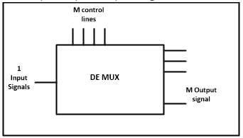
A demultiplexer, also known as a demux, is a combinational logic circuit that takes a single input signal and distributes it to one of several possible output lines. It is the opposite of a multiplexer, which takes multiple input signals and selects one of them to be transmitted to a single output line.
A 1-to-8 demultiplexer has a single input line and eight output lines. The input line is typically denoted as D, and the output lines are denoted as Y0, Y1, Y2, Y3, Y4, Y5, Y6, and Y7.
Select Lines
The select lines of a demultiplexer determine which output line the input signal will be distributed to. In the case of a 1-to-8 demultiplexer, the number of select lines required can be calculated using the formula:
Number of select lines = log2(Number of output lines)
In this case, the number of output lines is 8, so the number of select lines required is:
Number of select lines = log2(8) = 3
Therefore, the correct answer is option B, which states that three select lines are required for a 1-to-8 demultiplexer.
Explanation
The reason why three select lines are required for a 1-to-8 demultiplexer can be understood by considering the binary representation of the output lines. Since there are eight output lines, each output line can be uniquely identified by a three-bit binary number.
The select lines are used to control which output line will receive the input signal. By manipulating the select lines, we can set the binary representation of the desired output line. For example, if the select lines are set to 000, the input signal will be distributed to the Y0 output line. If the select lines are set to 001, the input signal will be distributed to the Y1 output line, and so on.
By using three select lines, we can represent all eight possible combinations of the select lines, which correspond to the eight output lines of the demultiplexer. Therefore, three select lines are required to fully control a 1-to-8 demultiplexer.
A Demultiplexer has ________.- a)One data input and a number of selection inputs, and several outputs
- b)One input and one output
- c)Several inputs and several outputs
- d)Several inputs and one output
Correct answer is option 'A'. Can you explain this answer?
A Demultiplexer has ________.
a)
One data input and a number of selection inputs, and several outputs
b)
One input and one output
c)
Several inputs and several outputs
d)
Several inputs and one output
|
|
Ishan Unni answered |
Demultiplexer:
A demultiplexer (or demux) is a combinational logic circuit that takes in one input and distributes it to one of the multiple output lines based on the selection inputs. In other words, it allows the selection of one output line from multiple possible output lines based on the value of the selection inputs.
Function and Structure:
The demultiplexer has one data input and a number of selection inputs, which determine the output line to which the input data is directed. The demultiplexer has several outputs, each corresponding to one output line. The number of selection inputs determines the total number of output lines available.
Working:
When the selection inputs are applied, they determine the binary code representing the desired output line. The input data is then directed to the corresponding output line, while all other output lines remain inactive.
Example:
Let's consider a 1-to-4 demultiplexer. It has one data input (D), two selection inputs (S1 and S0), and four output lines (Y0, Y1, Y2, Y3). The selection inputs can be used to represent the binary code of the desired output line.
Truth Table:
The truth table for the 1-to-4 demultiplexer would be as follows:
S1 | S0 | D | Y0 | Y1 | Y2 | Y3
------------------------------
0 | 0 | D | 1 | 0 | 0 | 0
0 | 1 | D | 0 | 1 | 0 | 0
1 | 0 | D | 0 | 0 | 1 | 0
1 | 1 | D | 0 | 0 | 0 | 1
Explanation:
The demultiplexer has one data input (D) and a number of selection inputs (S1 and S0). Based on the values of S1 and S0, the input data D is directed to one of the four output lines (Y0, Y1, Y2, Y3). The output lines that are not selected remain inactive (0), while the selected output line becomes active (1).
Therefore, a demultiplexer has one data input and a number of selection inputs, and several outputs, as stated in option 'A'.
In a multiplexer, the selection of a particular input line is controlled by ___________- a)Data controller
- b)Selected lines
- c)Logic gates
- d)Both data controller and selected lines
Correct answer is option 'B'. Can you explain this answer?
In a multiplexer, the selection of a particular input line is controlled by ___________
a)
Data controller
b)
Selected lines
c)
Logic gates
d)
Both data controller and selected lines
|
|
Bhumi Patel answered |
Introduction:
A multiplexer (MUX) is a digital circuit that allows multiple input lines to be selected and routed to a single output line. It is commonly used in digital systems to save space and reduce complexity by reducing the number of required connections. The selection of a particular input line in a multiplexer is controlled by selected lines.
Explanation:
A multiplexer consists of multiple input lines, a set of selected lines, and a single output line. The number of input lines in a multiplexer is typically a power of 2, represented as 2^n, where n is the number of selected lines. For example, a 4-to-1 multiplexer has 4 input lines and 2 selected lines.
Selected lines:
The selected lines in a multiplexer are used to control the selection of the input lines. Each selected line corresponds to a specific input line. The binary value of the selected lines determines which input line is selected. For example, in a 4-to-1 multiplexer, the selected lines can have a binary value of 00, 01, 10, or 11. Each binary value corresponds to one of the four input lines.
Data controller:
The data controller, also known as the control unit, is responsible for generating and controlling the selected lines' binary values. It receives control signals from the system and generates the appropriate binary values for the selected lines. The control signals can be generated based on various factors, such as user input, system conditions, or timing requirements.
Selection of input line:
The selected lines' binary values determine which input line is selected and connected to the output line. Each selected line activates a specific set of logic gates that perform the switching function. The logic gates compare the binary value of the selected lines with the binary value of the input lines and activate the corresponding input line.
Conclusion:
In conclusion, the selection of a particular input line in a multiplexer is controlled by the selected lines. The selected lines' binary values determine which input line is selected and connected to the output line. The data controller is responsible for generating and controlling the selected lines' binary values based on the control signals received from the system.
A basic multiplexer principle can be demonstrated through the use of a ___________- a)Single-pole relay
- b)DPDT switch
- c)Rotary switch
- d)Linear stepper
Correct answer is option 'C'. Can you explain this answer?
A basic multiplexer principle can be demonstrated through the use of a ___________
a)
Single-pole relay
b)
DPDT switch
c)
Rotary switch
d)
Linear stepper
|
|
Subhankar Pillai answered |
Demonstration of Multiplexer Principle using Rotary Switch
Multiplexer is a digital circuit that selects one of several input signals and forwards the selected input to a single output line. The basic multiplexer principle can be demonstrated using a rotary switch.
Working Principle:
- A rotary switch is a type of switch that rotates around a central axis and has multiple positions. Each position corresponds to a different input signal.
- The common terminal of the rotary switch is connected to the output line, and the other terminals are connected to the input lines.
- As the switch is rotated, the common terminal is connected to a different input line and the selected input is forwarded to the output line.
Demonstration:
- Connect a rotary switch to several input signals and a single output line.
- Connect the common terminal of the rotary switch to the output line.
- Connect the other terminals of the rotary switch to the input signals.
- Rotate the switch and observe the output line. The output line should correspond to the selected input signal.
Advantages of using a Rotary Switch:
- Rotary switches are easy to use and can handle multiple input signals.
- They are reliable and durable, and can withstand high voltages and currents.
- They are available in different configurations and sizes to suit various applications.
Conclusion:
Thus, the basic multiplexer principle can be demonstrated using a rotary switch. Rotary switches are widely used in digital circuits and offer several advantages over other types of switches.
Which is the major functioning responsibility of the multiplexing combinational circuit?- a)Decoding the binary information
- b)Generation of all minterms in an output function with OR-gate
- c)Generation of selected path between multiple sources and a single destination
- d)Encoding of binary information
Correct answer is option 'C'. Can you explain this answer?
Which is the major functioning responsibility of the multiplexing combinational circuit?
a)
Decoding the binary information
b)
Generation of all minterms in an output function with OR-gate
c)
Generation of selected path between multiple sources and a single destination
d)
Encoding of binary information
|
|
Sudhir Patel answered |
The major functioning responsibility of the multiplexing combinational circuit is generation of selected path between multiple sources and a single destination because it makes the circuit too flexible. A multiplexer (or MUX) is a device that selects one of several analog or digital input signals and forwards the selected input into a single line, depending on the active select lines.
In a multiplexer, the selection of a particular input line is controlled by ___________- a)Data controller
- b)Selected lines
- c)Logic gates
- d)Both data controller and selected lines
Correct answer is option 'B'. Can you explain this answer?
In a multiplexer, the selection of a particular input line is controlled by ___________
a)
Data controller
b)
Selected lines
c)
Logic gates
d)
Both data controller and selected lines
|
|
Lekshmi Kulkarni answered |
Selection of Input Line in a Multiplexer
A multiplexer is a combinational circuit that selects one of several input lines and routes it to a single output line. The selection of a particular input line in a multiplexer is controlled by the selected lines.
What are Selected Lines?
Selected lines, also known as select lines or control lines, are the inputs to the multiplexer that determine which input line is selected. The number of selected lines required in a multiplexer depends on the number of input lines. For example, if there are 2^n input lines, n select lines are required.
Working of a Multiplexer
A multiplexer consists of two main components: input lines and selected lines. The input lines carry the data that needs to be selected, and the selected lines control the selection process. The selected lines are connected to the control inputs of the logic gates inside the multiplexer.
Logic Gates in a Multiplexer
The logic gates inside a multiplexer perform the selection process. The selected lines are connected to the control inputs of these gates. The logic gates compare the binary values of the selected lines and generate the necessary control signals to select the appropriate input line.
Data Controller
The data controller is not directly involved in the selection of input lines in a multiplexer. The data controller is responsible for managing the data flow and controlling the timing of the multiplexer. It ensures that the data is properly synchronized and routed to the correct output.
Conclusion
In conclusion, the selection of a particular input line in a multiplexer is controlled by the selected lines. The selected lines are connected to the control inputs of the logic gates inside the multiplexer. These gates compare the binary values of the selected lines and generate the necessary control signals to select the desired input line. The data controller, on the other hand, is responsible for managing the data flow and controlling the timing of the multiplexer.
What is a multiplexer?- a)It is a type of decoder which decodes several inputs and gives one output
- b)A multiplexer is a device which converts many signals into one
- c)It takes one input and results into many output
- d)It is a type of encoder which decodes several inputs and gives one output
Correct answer is option 'B'. Can you explain this answer?
What is a multiplexer?
a)
It is a type of decoder which decodes several inputs and gives one output
b)
A multiplexer is a device which converts many signals into one
c)
It takes one input and results into many output
d)
It is a type of encoder which decodes several inputs and gives one output

|
Isha Bajaj answered |
Multiplexer
A multiplexer is a digital device that combines multiple input signals into a single output signal. It is commonly referred to as a "MUX" or "data selector." The primary purpose of a multiplexer is to reduce the number of transmission lines required to transmit multiple signals.
Working Principle
A multiplexer operates on the principle of selecting one input signal from several available inputs and forwarding it to the output. It uses a select line or control input to determine which input signal to pass through. The select line controls the operation of the multiplexer by activating the corresponding input line.
Features and Applications
Multiplexers have various features and find applications in different areas, including:
- Signal Combination: A multiplexer combines multiple input signals into a single output signal, reducing the number of transmission lines required.
- Data Transmission: It is commonly used in data communication systems to transmit multiple data streams over a single channel. For example, in telecommunications, multiplexers are used to combine voice, video, and data signals into a single transmission line.
- Data Routing: Multiplexers can be used to route data from multiple sources to a single destination. This is especially useful in computer networks, where data packets from different sources need to be directed to a specific destination.
- Memory Addressing: Multiplexers can be used to select memory addresses in computer systems. By using a multiplexer, the number of address lines required can be reduced.
- Logic Function Implementation: Multiplexers can be used to implement various logic functions, including AND, OR, and XOR gates. By selecting the appropriate input lines and controlling the select line, different logic functions can be achieved.
Types of Multiplexers
There are different types of multiplexers based on the number of inputs they can handle. The most common types include:
- 2-to-1 Multiplexer: It has two input lines and one output line. The select line determines which input is connected to the output.
- 4-to-1 Multiplexer: It has four input lines and one output line. It uses two select lines to determine the active input.
- 8-to-1 Multiplexer: It has eight input lines and one output line. It uses three select lines to select the desired input.
- n-to-1 Multiplexer: It can handle 'n' input lines and one output line. The number of select lines required depends on the number of input lines.
Conclusion
In conclusion, a multiplexer is a digital device that combines multiple input signals into a single output signal. It is widely used in various applications such as data transmission, data routing, and logic function implementation. By selecting the appropriate input lines using a control input, a multiplexer can effectively reduce the number of transmission lines required, improving efficiency and reducing complexity in digital systems.
What is the function of an enable input on a multiplexer chip?- a)To apply Vcc
- b)To connect ground
- c)To active the entire chip
- d)To active one half of the chip
Correct answer is option 'C'. Can you explain this answer?
What is the function of an enable input on a multiplexer chip?
a)
To apply Vcc
b)
To connect ground
c)
To active the entire chip
d)
To active one half of the chip
|
|
Rajat Kapoor answered |
Function of the Enable Input in a Multiplexer Chip
The enable input on a multiplexer (MUX) chip plays a crucial role in determining the operational state of the device. Understanding its function is essential for effectively utilizing multiplexers in circuit designs.
What is a Multiplexer?
- A multiplexer is a combinational circuit that selects one of many input signals and forwards the selected input into a single line.
- It is commonly used for data routing in various applications.
Role of the Enable Input
- The enable input is a control line that activates or deactivates the multiplexer.
- When the enable input is asserted (typically set to high), the multiplexer is allowed to function normally, selecting the appropriate input based on the selection lines.
- When the enable input is deasserted (usually set to low), the multiplexer becomes inactive, effectively disabling all outputs.
Importance of Activation
- By controlling the enable input, designers can manage the power consumption of the multiplexer, ensuring that it only operates when needed.
- This feature is particularly useful in complex systems where multiple components must be selectively activated to optimize performance and reduce power usage.
Conclusion
- In summary, the correct answer to the function of the enable input on a multiplexer chip is option 'C': to activate the entire chip.
- This functionality allows for efficient control over the multiplexer, making it an essential aspect of digital circuit design in Electronics and Communication Engineering.
Which combinational circuit is renowned for selecting a single input from multiple inputs & directing the binary information to output line?- a)Data Selector
- b)Data distributor
- c)Both data selector and data distributor
- d)DeMultiplexer
Correct answer is option 'A'. Can you explain this answer?
Which combinational circuit is renowned for selecting a single input from multiple inputs & directing the binary information to output line?
a)
Data Selector
b)
Data distributor
c)
Both data selector and data distributor
d)
DeMultiplexer
|
|
Akshay Nair answered |
The multiplexer (MUX) is renowned for selecting a single input from multiple inputs.
Why is a demultiplexer called a data distributor?- a)The input will be distributed to one of the outputs
- b)One of the inputs will be selected for the output
- c)The output will be distributed to one of the inputs
- d)Single input to Single Output
Correct answer is option 'A'. Can you explain this answer?
Why is a demultiplexer called a data distributor?
a)
The input will be distributed to one of the outputs
b)
One of the inputs will be selected for the output
c)
The output will be distributed to one of the inputs
d)
Single input to Single Output
|
|
Niti Desai answered |
Introduction:
A demultiplexer, also known as a data distributor, is a digital circuit that takes one input and distributes it to one of several outputs based on the control signals. It is the opposite of a multiplexer, which takes multiple inputs and selects one output.
Explanation:
The reason why a demultiplexer is called a data distributor is because it distributes the input data to one of the outputs based on the control signals. Let's understand this in more detail:
1. Input Distribution:
- A demultiplexer has one input and multiple outputs.
- When a data signal is applied to the input, it is distributed to one of the outputs based on the control signals.
- The control signals determine which output will receive the input data.
2. Control Signals Selection:
- The demultiplexer has control inputs that are used to select one of the outputs.
- These control inputs determine which output will be active and receive the input data.
- For example, if there are 2^n outputs, n control inputs will be required to select one of the outputs.
- The control inputs can be set to binary values, and each combination of control inputs will select a specific output.
3. Output Distribution:
- Once the control inputs have selected a specific output, the input data is distributed to that output.
- The selected output will receive the input data, while the other outputs remain inactive.
- This distribution of input data to one of the outputs is why a demultiplexer is called a data distributor.
4. Single Input, Multiple Outputs:
- A key characteristic of a demultiplexer is that it has a single input and multiple outputs.
- This means that the demultiplexer can take a single data signal and distribute it to different destinations.
- Each output represents a different destination for the input data, and the demultiplexer decides which output will receive the data based on the control signals.
Conclusion:
In summary, a demultiplexer is called a data distributor because it takes a single input and distributes it to one of the outputs based on the control signals. The input is distributed to the selected output, while the other outputs remain inactive. This characteristic of a demultiplexer makes it a useful circuit for distributing data to multiple destinations.
Which combinational circuit is renowned for selecting a single input from multiple inputs & directing the binary information to output line?- a)Data Selector
- b)Data distributor
- c)Both data selector and data distributor
- d)DeMultiplexer
Correct answer is option 'A'. Can you explain this answer?
Which combinational circuit is renowned for selecting a single input from multiple inputs & directing the binary information to output line?
a)
Data Selector
b)
Data distributor
c)
Both data selector and data distributor
d)
DeMultiplexer
|
|
Tanishq Joshi answered |
The combinational circuit renowned for selecting a single input from multiple inputs is called a multiplexer (MUX).
The word demultiplex means ___________- a)One into many
- b)Many into one
- c)Distributor
- d)One into many as well as Distributor
Correct answer is option 'D'. Can you explain this answer?
The word demultiplex means ___________
a)
One into many
b)
Many into one
c)
Distributor
d)
One into many as well as Distributor
|
|
Sudhir Patel answered |
The word demultiplex means “one into many” and distributor. A demultiplexer sends a single input to multiple outputs, depending on the select lines. It is clear from the diagram:
The enable input is also known as ___________- a)Select input
- b)Decoded input
- c)Strobe
- d)Sink
Correct answer is option 'C'. Can you explain this answer?
The enable input is also known as ___________
a)
Select input
b)
Decoded input
c)
Strobe
d)
Sink
|
|
Snehal Bajaj answered |
Introduction:
The enable input, also known as the strobe input, is an important component in digital circuits. It is used to control the functioning of a circuit by enabling or disabling its operation. In this case, the correct answer to the given question is option 'C', which states that the enable input is also known as strobe.
Explanation:
The enable input, or strobe, is a control signal that determines whether the circuit should be active or inactive. It acts as a gatekeeper, allowing or blocking the flow of data within the circuit. When the enable input is activated, the circuit operates and responds to its inputs. Conversely, when the enable input is deactivated, the circuit becomes inactive and does not produce any output.
The enable input is commonly used in various digital circuits, such as multiplexers, demultiplexers, flip-flops, and registers. It provides a way to selectively enable or disable these circuits based on specific conditions or timing requirements. By controlling the enable input, the circuit can be synchronized with other components or triggered at specific moments.
Comparison with other options:
Let's briefly compare the enable input with the other options provided:
a) Select input: The select input is used to choose one of multiple inputs in a circuit. It is commonly found in multiplexers and demultiplexers. While the enable input can be used in conjunction with the select input to enable or disable the circuit based on the selected input, the enable input and select input are not the same.
b) Decoded input: The decoded input is not a commonly used term in the context of digital circuits. It is not directly related to the enable input or its functionality.
Conclusion:
In summary, the enable input, also known as the strobe, is a control signal used to enable or disable the operation of a digital circuit. It acts as a gatekeeper, allowing or blocking the flow of data within the circuit. The enable input is commonly used in various digital circuits and plays a crucial role in controlling their functioning.
In a multiplexer the output depends on its ___________- a)Data inputs
- b)Select inputs
- c)Select outputs
- d)Enable pin
Correct answer is option 'B'. Can you explain this answer?
In a multiplexer the output depends on its ___________
a)
Data inputs
b)
Select inputs
c)
Select outputs
d)
Enable pin
|
|
Pranavi Reddy answered |
Answer:
A multiplexer is a combinational circuit that selects one of many input signals and forwards it to a single output line. The selection of the input signal is determined by the select inputs of the multiplexer.
The output of a multiplexer depends on its select inputs (also known as control inputs or select lines). These select inputs determine which input signal is to be forwarded to the output. The number of select inputs determines the number of input signals that can be selected by the multiplexer.
Explanation:
A multiplexer has multiple data inputs, but only one output. The output of the multiplexer is determined by the select inputs. The select inputs act as control signals that determine which data input is selected.
When the select inputs are set to a particular combination, the multiplexer forwards the corresponding data input to the output. The selected data input is then propagated to the output line.
The number of select inputs determines the number of data inputs that can be selected. For example, a 2-to-1 multiplexer has two data inputs and one select input. The select input can be either 0 or 1, and the corresponding data input is selected based on the select input.
In a multiplexer, the select inputs can be controlled using various methods. For example, the select inputs can be connected to switches or logic gates to set their values. The selected data input can also be determined based on the conditions or logic applied to the select inputs.
Therefore, the output of a multiplexer depends on its select inputs. The select inputs determine which data input is selected and forwarded to the output. The output is a reflection of the selected data input.
Key Points:
- A multiplexer selects one of many input signals and forwards it to a single output line.
- The output of a multiplexer depends on its select inputs.
- The select inputs determine which data input is selected and forwarded to the output.
- The number of select inputs determines the number of data inputs that can be selected.
- The selected data input is propagated to the output line.
Name the following figure.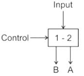
- a)Multiplexer
- b)De-multiplexer
- c)Combinational circuit
- d)Encoder
Correct answer is option 'B'. Can you explain this answer?
Name the following figure.
a)
Multiplexer
b)
De-multiplexer
c)
Combinational circuit
d)
Encoder
|
|
Sudhir Patel answered |
Multiplexer: Multiplexer is a device that has multiple inputs and single line output.
De-multiplexer: De-multiplexer is a device that has a signal inputs line and multiple line outputs.
The given figure has one input and two outputs. Hence it is De-multiplexer.
Combinational circuit:
- Combinational and sequential circuits are the digital circuits made using logic gates
- Present output depends on the present input only
- No feedback is present
- No memory is present
Encoder: Encoder is used to converter other codes to binary
What is the function of an enable input on a multiplexer chip?- a)To apply Vcc
- b)To connect ground
- c)To active the entire chip
- d)To active one half of the chip
Correct answer is option 'C'. Can you explain this answer?
What is the function of an enable input on a multiplexer chip?
a)
To apply Vcc
b)
To connect ground
c)
To active the entire chip
d)
To active one half of the chip
|
|
Sudhir Patel answered |
Enable input is used to active the chip, when enable is high the chip works (ACTIVE), when enable is low the chip does not work (MEMORY). However, Enable can be Active-High or Active-Low, indicating it is active either when it is connected to VCC or GND respectively.
It is possible for an enable or strobe input to undergo an expansion of two or more MUX ICs to the digital multiplexer with the proficiency of large number of ___________- a)Inputs
- b)Outputs
- c)Selection lines
- d)Enable lines
Correct answer is option 'A'. Can you explain this answer?
It is possible for an enable or strobe input to undergo an expansion of two or more MUX ICs to the digital multiplexer with the proficiency of large number of ___________
a)
Inputs
b)
Outputs
c)
Selection lines
d)
Enable lines
|
|
Ravi Singh answered |
It is possible for an enable or strobe input to undergo an expansion of two or more MUX ICs to the digital multiplexer with the proficiency of large number of inputs.
It is possible for an enable or strobe input to undergo an expansion of two or more MUX ICs to the digital multiplexer with the proficiency of large number of ___________- a)Inputs
- b)Outputs
- c)Selection lines
- d)Enable lines
Correct answer is option 'A'. Can you explain this answer?
It is possible for an enable or strobe input to undergo an expansion of two or more MUX ICs to the digital multiplexer with the proficiency of large number of ___________
a)
Inputs
b)
Outputs
c)
Selection lines
d)
Enable lines
|
|
Sudhir Patel answered |
It is possible for an enable or strobe input to undergo an expansion of two or more MUX ICs to the digital multiplexer with the proficiency of large number of inputs.
Select the word which can be replaced for the given sentence. Q. One who is employed to drive a car _______- a)Chauffeur
- b)rider
- c)driver
- d)sprinter
Correct answer is option 'A'. Can you explain this answer?
Select the word which can be replaced for the given sentence.
Q. One who is employed to drive a car _______
a)
Chauffeur
b)
rider
c)
driver
d)
sprinter
|
|
Manasa Reddy answered |
**Explanation:**
To determine the correct answer, let's analyze the given sentence:
"One who is employed to drive a car _______"
The sentence is asking for a word that describes someone who is employed to drive a car. Let's analyze the options:
a) Chauffeur: This word refers to a person employed to drive a private car. It is commonly used to describe a professional driver who drives luxury vehicles for their clients. This option fits the context of the sentence and is the correct answer.
b) Rider: This word generally refers to someone who rides a bicycle, motorcycle, or any other vehicle. It does not specifically describe someone employed to drive a car. Thus, this option is incorrect.
c) Driver: This word generally refers to someone who operates a vehicle. While it is a broad term that can include someone employed to drive a car, it does not specifically convey the idea of employment. Therefore, this option is not as precise as the correct answer.
d) Sprinter: This word refers to a person who specializes in running short distances at a high speed. It does not relate to driving a car, so it is not the correct answer.
Therefore, after analyzing the options and considering the context of the sentence, we can conclude that the correct answer is option 'A' - Chauffeur.
If the number of n selected input lines is equal to 2^m then it requires _____ select lines.- a)2
- b)m
- c)n
- d)2n
Correct answer is option 'B'. Can you explain this answer?
If the number of n selected input lines is equal to 2^m then it requires _____ select lines.
a)
2
b)
m
c)
n
d)
2n
|
|
Sarita Yadav answered |
If the number of n selected input lines is equal to 2^m then it requires m select lines to select one of m select lines.
_________ is the device having 1 input and N outputs.- a)Shift register
- b)Multiplexer
- c)De-multiplexer
- d)Counter
Correct answer is option 'C'. Can you explain this answer?
_________ is the device having 1 input and N outputs.
a)
Shift register
b)
Multiplexer
c)
De-multiplexer
d)
Counter
|
|
Sudhir Patel answered |
Demultiplexer (DEMUX) is used in digital signal processing, for enhancing the input signal. The input and output ratio in a DEMUX is given by;
1 : 2n, where n = 1, 2, 3, and so on.
Ex: 1 : 1, 1 : 2, 1 : 4, 1 : 8, etc.
Therefore, for one data input they have several (N) outputs.
The logic diagram shown in the figure represents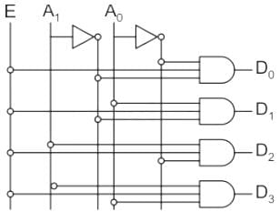
- a)1 to 4 Demultiplexer
- b)4 to 2 Encoder
- c)1 to 4 Decoder
- d)4 to 1 Multiplexer
Correct answer is option 'A'. Can you explain this answer?
The logic diagram shown in the figure represents
a)
1 to 4 Demultiplexer
b)
4 to 2 Encoder
c)
1 to 4 Decoder
d)
4 to 1 Multiplexer
|
|
Sudhir Patel answered |
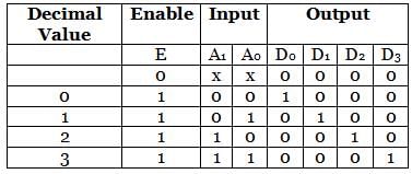
The given logic circuit represents 2 to 4 decoder and 1 to 4 line demultiplexer.
For the decoder, the inputs are A1 and A0, and the enable is input E.
For demultiplexer, input E provides the data, while other inputs accept the selected variables.
This can be verified from the table given below:
A basic multiplexer principle can be demonstrated through the use of a ___________- a)Single-pole relay
- b)DPDT switch
- c)Rotary switch
- d)Linear stepper
Correct answer is option 'C'. Can you explain this answer?
A basic multiplexer principle can be demonstrated through the use of a ___________
a)
Single-pole relay
b)
DPDT switch
c)
Rotary switch
d)
Linear stepper
|
|
Sarita Yadav answered |
A basic multiplexer principle can be demonstrated through the use of a rotary switch. Since its behaviour is similar to the multiplexer. There are around 10 digits out of which one is selected one at a time and fed to the output.
A digital multiplexer is a combinational circuit that selects ___________- a)One digital information from several sources and transmits the selected one
- b)Many digital information and convert them into one
- c)Many decimal inputs and transmits the selected information
- d)Many decimal outputs and accepts the selected information
Correct answer is option 'A'. Can you explain this answer?
A digital multiplexer is a combinational circuit that selects ___________
a)
One digital information from several sources and transmits the selected one
b)
Many digital information and convert them into one
c)
Many decimal inputs and transmits the selected information
d)
Many decimal outputs and accepts the selected information
|
|
Sarita Yadav answered |
A digital multiplexer is a combinational circuit that selects one digital information from several sources and transmits the selected information on a single output line depending on the status of the select lines. That is why it is also known as a data selector.
What is a multiplexer?- a)It is a type of decoder which decodes several inputs and gives one output
- b)A multiplexer is a device which converts many signals into one
- c)It takes one input and results into many output
- d)It is a type of encoder which decodes several inputs and gives one output
Correct answer is option 'B'. Can you explain this answer?
What is a multiplexer?
a)
It is a type of decoder which decodes several inputs and gives one output
b)
A multiplexer is a device which converts many signals into one
c)
It takes one input and results into many output
d)
It is a type of encoder which decodes several inputs and gives one output
|
|
Yash Patel answered |
A multiplexer (or MUX) is a device that selects one of several analog or digital input signals and forwards the selected input into a single line, depending on the active select lines.
Most demultiplexers facilitate which type of conversion?- a)Decimal-to-hexadecimal
- b)Single input, multiple outputs
- c)AC to DC
- d)Odd parity to even parity
Correct answer is option 'B'. Can you explain this answer?
Most demultiplexers facilitate which type of conversion?
a)
Decimal-to-hexadecimal
b)
Single input, multiple outputs
c)
AC to DC
d)
Odd parity to even parity
|
|
Sudhir Patel answered |
A demultiplexer sends a single input to multiple outputs, depending on the select lines. Demultiplexer converts single input into multiple outputs.
Which IC is used for the implementation of 1-to-16 DEMUX?- a)IC 74154
- b)IC 74155
- c)IC 74139
- d)IC 74138
Correct answer is option 'A'. Can you explain this answer?
Which IC is used for the implementation of 1-to-16 DEMUX?
a)
IC 74154
b)
IC 74155
c)
IC 74139
d)
IC 74138
|
|
Sudhir Patel answered |
IC 74154 is used for the implementation of 1-to-16 DEMUX, whose output is inverted input.
Chapter doubts & questions for Data Selectors & Multiplexers - Digital Circuits 2025 is part of Electronics and Communication Engineering (ECE) exam preparation. The chapters have been prepared according to the Electronics and Communication Engineering (ECE) exam syllabus. The Chapter doubts & questions, notes, tests & MCQs are made for Electronics and Communication Engineering (ECE) 2025 Exam. Find important definitions, questions, notes, meanings, examples, exercises, MCQs and online tests here.
Chapter doubts & questions of Data Selectors & Multiplexers - Digital Circuits in English & Hindi are available as part of Electronics and Communication Engineering (ECE) exam.
Download more important topics, notes, lectures and mock test series for Electronics and Communication Engineering (ECE) Exam by signing up for free.
Digital Circuits
76 videos|175 docs|70 tests
|
|
© EduRev
|
Education Revolution
|


|


Signup on EduRev and stay on top of your study goals
10M+ students crushing their study goals daily