


All Exams >
Electronics and Communication Engineering (ECE) >
Digital Circuits >
All Questions
All questions of Encoders & Decoders for Electronics and Communication Engineering (ECE) Exam
Decoder is constructed from ________________- a)Inverters
- b)AND gates
- c)Inverters and AND gates
- d)None of the mentioned
Correct answer is option 'C'. Can you explain this answer?
Decoder is constructed from ________________
a)
Inverters
b)
AND gates
c)
Inverters and AND gates
d)
None of the mentioned
|
|
Jaideep Chaudhary answered |
Explanation:
A decoder is a combinational logic circuit that converts binary information from n input lines to a maximum of 2^n unique output lines. It is used to decode a binary code of n bits to a set of 2^n unique outputs.
A decoder is constructed from inverters and AND gates. Inverters are used to complement the input signals, while AND gates are used to combine the complemented and non-complemented inputs to form the output signals.
Construction of a Decoder:
A decoder is constructed using the following steps:
1. Determine the number of input lines (n) and output lines (2^n) required for the desired decoding scheme.
2. Construct the truth table for the decoder. The truth table lists all possible combinations of inputs and their corresponding outputs.
3. Identify the output functions for each output line. The output functions are derived based on the desired decoding scheme and the truth table.
4. Use the output functions to construct the logic gates required for each output line. Inverters are used to complement the input signals, while AND gates are used to combine the complemented and non-complemented inputs.
5. Connect the logic gates together to form the decoder circuit. The inputs are connected to the inverters, and the outputs of the inverters are connected to the AND gates. The outputs of the AND gates represent the decoded output lines.
Advantages of using Inverters and AND gates:
1. Inverters are simple and easy to implement logic gates. They can be easily constructed using basic electronic components such as transistors or diodes.
2. AND gates are also simple and easy to implement logic gates. They can be constructed using basic electronic components such as transistors or diodes.
3. Using inverters and AND gates allows for a compact and efficient decoder design.
4. Inverters and AND gates can be easily cascaded together to construct decoders with larger numbers of input and output lines.
Conclusion:
In conclusion, a decoder is constructed from inverters and AND gates. Inverters are used to complement the input signals, while AND gates are used to combine the complemented and non-complemented inputs to form the output signals. This combination of inverters and AND gates allows for the efficient decoding of binary information.

DTMF stands for ________________- a)Dual Tone Magnetic Frequency
- b)Double Tone Magnetic Frequency
- c)Dual Tone Multiple Frequency
- d)Dual Tone Mechanical Frequency
Correct answer is option 'C'. Can you explain this answer?
DTMF stands for ________________
a)
Dual Tone Magnetic Frequency
b)
Double Tone Magnetic Frequency
c)
Dual Tone Multiple Frequency
d)
Dual Tone Mechanical Frequency
|
|
Sarita Yadav answered |
DTMF is the short form of Dual Tone Multiple Frequency.
How is an encoder different from a decoder?- a)The output of an encoder is a binary code for 1-of-N input
- b)The output of a decoder is a binary code for 1-of-N input
- c)The output of an encoder is a binary code for N-of-1 output
- d)The output of a decoder is a binary code for N-of-1 output
Correct answer is option 'A'. Can you explain this answer?
How is an encoder different from a decoder?
a)
The output of an encoder is a binary code for 1-of-N input
b)
The output of a decoder is a binary code for 1-of-N input
c)
The output of an encoder is a binary code for N-of-1 output
d)
The output of a decoder is a binary code for N-of-1 output
|
|
Madhavan Nair answered |
Encoder vs Decoder:
Encoder and decoder are digital circuits that perform different functions. An encoder is a circuit that converts an active input signal into a coded output signal. In contrast, a decoder is a circuit that converts a coded input signal into an active output signal. Let's dive into the differences between the two:
Output of an Encoder:
The output of an encoder is a binary code for 1-of-N input. Here's what this means:
- An encoder has N input lines and 2^N output lines.
- When a signal is active on one of the input lines, the encoder produces a binary code on its output lines that represents the active input line.
- The binary code is typically in the form of a 1-of-N code, which means that only one of the output lines is active at a time, and the rest are inactive.
Output of a Decoder:
The output of a decoder is a binary code for N-of-1 output. Here's what this means:
- A decoder has 2^N input lines and N output lines.
- When a binary code is applied to the input lines, the decoder activates the corresponding output line.
- The binary code is typically in the form of a N-of-1 code, which means that only one of the input lines is active at a time, and the rest are inactive.
Conclusion:
In summary, an encoder converts an active input signal into a coded output signal, while a decoder converts a coded input signal into an active output signal. The key difference between the two is the type of binary code that they produce. An encoder produces a 1-of-N code, while a decoder produces a N-of-1 code.
Which of the following are building blocks of encoders?- a)NOT gate
- b)OR gate
- c)AND gate
- d)NAND gate
Correct answer is option 'B'. Can you explain this answer?
Which of the following are building blocks of encoders?
a)
NOT gate
b)
OR gate
c)
AND gate
d)
NAND gate
|
|
Sarita Yadav answered |
Encoders are made up of three OR gates.
___________ converts binary-coded information to unique outputs such as decimal, octal digits, etc.- a)Decoder
- b)Demultiplexing
- c)Multiplexing
- d)Encoder
Correct answer is option 'A'. Can you explain this answer?
___________ converts binary-coded information to unique outputs such as decimal, octal digits, etc.
a)
Decoder
b)
Demultiplexing
c)
Multiplexing
d)
Encoder
|
|
Maya Banerjee answered |
Understanding Decoders
Decoders are essential components in digital electronics, used to convert binary-coded information into recognizable outputs.
Function of a Decoder
- A decoder takes a binary input and activates one specific output line corresponding to that input.
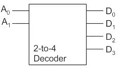
- For instance, a 2-to-4 decoder takes 2 input bits and generates 4 unique outputs, where only one output is HIGH (active) at any time.
Types of Outputs
- Decoders are versatile and can produce outputs in various numeral systems:
- Decimal: Converts binary to base-10 numbers.
- Octal: Converts binary to base-8 numbers.
- Hexadecimal: Converts binary to base-16 numbers.
Applications of Decoders
- Used in memory address decoding in microprocessors.
- Facilitate data routing in communication systems.
- Enable control functions in complex digital systems.
Comparison with Other Options
- Demultiplexing: Distributes a single input signal to multiple outputs but does not convert binary codes.
- Multiplexing: Combines multiple input signals into one output line, which is the opposite of decoding.
- Encoder: Converts input signals from multiple sources into a binary format, essentially performing the reverse function of a decoder.
Conclusion
The correct answer to the question is option 'A' because decoders uniquely convert binary-coded information into various numeral outputs, making them indispensable in digital systems.
Decoders are essential components in digital electronics, used to convert binary-coded information into recognizable outputs.
Function of a Decoder
- A decoder takes a binary input and activates one specific output line corresponding to that input.
- For instance, a 2-to-4 decoder takes 2 input bits and generates 4 unique outputs, where only one output is HIGH (active) at any time.
Types of Outputs
- Decoders are versatile and can produce outputs in various numeral systems:
- Decimal: Converts binary to base-10 numbers.
- Octal: Converts binary to base-8 numbers.
- Hexadecimal: Converts binary to base-16 numbers.
Applications of Decoders
- Used in memory address decoding in microprocessors.
- Facilitate data routing in communication systems.
- Enable control functions in complex digital systems.
Comparison with Other Options
- Demultiplexing: Distributes a single input signal to multiple outputs but does not convert binary codes.
- Multiplexing: Combines multiple input signals into one output line, which is the opposite of decoding.
- Encoder: Converts input signals from multiple sources into a binary format, essentially performing the reverse function of a decoder.
Conclusion
The correct answer to the question is option 'A' because decoders uniquely convert binary-coded information into various numeral outputs, making them indispensable in digital systems.
A decoder converts n inputs to __________ outputs.- a)n
- b)n2
- c)2n
- d)nn
Correct answer is option 'C'. Can you explain this answer?
A decoder converts n inputs to __________ outputs.
a)
n
b)
n2
c)
2n
d)
nn
|
|
Preethi Tiwari answered |
The correct answer is option 'C', which states that a decoder converts n inputs to 2^n outputs. Let's understand why this answer is correct by breaking it down into the following points:
1. Definition of a decoder:
- A decoder is a digital circuit that takes a binary input of n bits and produces 2^n possible output combinations.
- It is the opposite of an encoder, which converts 2^n inputs into n outputs.
2. Understanding the input:
- In the given question, it is stated that a decoder converts n inputs.
- Here, 'n' represents the number of input lines or bits that the decoder takes as input.
3. Understanding the output:
- The question asks about the number of outputs produced by the decoder.
- The answer option 'C' states that the decoder produces 2^n outputs.
- Here, '2^n' represents the total number of possible output combinations that can be generated from 'n' input lines.
4. Explanation:
- To understand why the decoder produces 2^n outputs, let's consider an example. Suppose we have a 2-input decoder with input lines A and B.
- The decoder will have 2^2 = 4 possible combinations of inputs: (00, 01, 10, 11).
- For each input combination, the decoder will produce a unique output combination.
- In this case, the decoder will have 4 outputs: Y0, Y1, Y2, and Y3.
- So, for 'n' input lines, the decoder will have 2^n possible combinations and hence, 2^n outputs.
5. Conclusion:
- Based on the above explanation, it is clear that a decoder converts 'n' inputs to 2^n outputs.
- Therefore, option 'C' is the correct answer to the given question.
If two inputs are active on a priority encoder, which will be coded on the output?- a)The lower value
- b)The higher value
- c)Neither of the inputs
- d)Both of the inputs
Correct answer is option 'B'. Can you explain this answer?
If two inputs are active on a priority encoder, which will be coded on the output?
a)
The lower value
b)
The higher value
c)
Neither of the inputs
d)
Both of the inputs
|
|
Sudhir Patel answered |
An encoder is a combinational circuit encoding the information of 2n input lines to n output lines, thus producing the binary equivalent of the input. If two inputs are active on a priority encoder, the input of higher value will be coded in the output.
An encoder has _________ input lines _________ output lines.- a)2n, n
- b)n2, 2
- c)n, 2n
- d)n, n2
Correct answer is option 'A'. Can you explain this answer?
An encoder has _________ input lines _________ output lines.
a)
2n, n
b)
n2, 2
c)
n, 2n
d)
n, n2
|
|
Sudhir Patel answered |
Encoder:
- It is a combinational circuit which converts decimal number into binary number.
- It consists 2n input lines and n output lines.
- They do not have any select lines.
How many OR gates are required for an octal-to-binary encoder?- a)3
- b)2
- c)8
- d)10
Correct answer is option 'A'. Can you explain this answer?
How many OR gates are required for an octal-to-binary encoder?
a)
3
b)
2
c)
8
d)
10
|
|
Ashwini Dasgupta answered |
Octal-to-binary Encoder:
An octal-to-binary encoder is a combinational circuit that converts an octal input into its binary equivalent. It has 8 input lines (3 bits) and 3 output lines (binary representation).
Solution:
To design an octal-to-binary encoder, we need to consider the input and output requirements. Since the encoder has 8 input lines, we need to use 8 OR gates to implement it.
Explanation:
1. Inputs: An octal input has 3 bits (8 possibilities: 000 to 111), so we need 8 input lines.
2. Outputs: The binary representation of an octal digit requires 3 bits. Since there are 8 octal digits (0 to 7), we need 3 output lines to represent the binary equivalent.
3. Truth Table: The octal-to-binary encoder truth table will have 8 rows (for 8 inputs) and 3 columns (for 3 outputs). Each row of the truth table represents the binary equivalent of the corresponding octal digit.
- For example, the truth table for input 0 (000) will have the output as 000, the truth table for input 1 (001) will have the output as 001, and so on.
4. Implementation: Each output line of the encoder requires an OR gate. Since there are 3 output lines, we need 3 OR gates.
- Each OR gate takes 8 inputs from the octal input lines and produces a single output for the corresponding bit of the binary representation.
- The output of each OR gate will be connected to its corresponding output line of the encoder.
5. Simplification: Since there are no specific requirements mentioned in the question, we assume a simple implementation using individual OR gates for each output line.
- More complex implementations using fewer gates are possible, but they are beyond the scope of this question.
6. Answer: Based on the above explanation, we require 8 OR gates to implement an octal-to-binary encoder.
Therefore, the correct answer is option 'A' - 3 OR gates are required for an octal-to-binary encoder.
Which of the following represents a number of output lines for a decoder with 4 input lines?- a)15
- b)16
- c)17
- d)18
Correct answer is option 'B'. Can you explain this answer?
Which of the following represents a number of output lines for a decoder with 4 input lines?
a)
15
b)
16
c)
17
d)
18
|
|
Meghana Chakraborty answered |
Answer:
A decoder is a combinational circuit that converts binary information from 'n' input lines to a maximum of 2^n unique output lines. The number of output lines for a decoder with 'n' input lines can be calculated using the formula 2^n.
In this case, we are given that the decoder has 4 input lines. So, the number of output lines can be calculated as 2^4, which is equal to 16.
Explanation:
A decoder is a digital circuit that takes binary inputs and produces a unique output line for each possible combination of input values. The number of input lines in a decoder determines the number of unique combinations it can represent.
In general, a decoder with 'n' input lines can represent 2^n unique combinations. This is because each input line can have two possible values, either 0 or 1. So, for 'n' input lines, there are 2^n possible combinations.
In this case, the decoder has 4 input lines. So, the number of unique combinations it can represent is 2^4, which is equal to 16. Therefore, the number of output lines for this decoder is 16.
Conclusion:
The correct answer is option 'B', which represents 16 output lines for a decoder with 4 input lines.
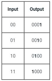
How many outputs will a decimal-to-BCD encoder have?- a)4
- b)8
- c)12
- d)16
Correct answer is option 'A'. Can you explain this answer?
How many outputs will a decimal-to-BCD encoder have?
a)
4
b)
8
c)
12
d)
16
|
|
Kalyan Roy answered |
Question Analysis:
The question asks about the number of outputs that a decimal-to-BCD (Binary Coded Decimal) encoder will have. To answer this question, we need to understand the concept of BCD encoding.
BCD Encoding:
BCD is a binary representation of decimal numbers, where each decimal digit is represented by a 4-bit binary code. In BCD encoding, the decimal numbers 0 to 9 are represented by their corresponding 4-bit binary codes.
Explanation:
A decimal-to-BCD encoder takes a decimal input and converts it into its BCD equivalent. The BCD output represents the individual digits of the decimal number in binary form.
To determine the number of outputs of a decimal-to-BCD encoder, we need to consider the maximum decimal digit that can be encoded. Since BCD is a 4-bit representation, it can encode decimal digits from 0 to 9.
Number of Decimal Digits:
The maximum number of decimal digits is determined by the largest decimal number that can be encoded. In BCD, the largest decimal number is 9. Therefore, the number of decimal digits is 1.
Number of Outputs:
Since we have one decimal digit, and each decimal digit is represented by a 4-bit BCD code, the number of outputs will be equal to the number of bits required to represent the decimal digits.
The BCD encoder will have 4 outputs because each decimal digit is represented by 4 bits in BCD encoding.
Answer:
Therefore, the correct answer is option A) 4.
Direction: Given question consists of two statements, one labeled as the 'Assertion (A)' and the other as 'Reason (R)'. You are to examine these two statements carefully and select the answers to these items using the codes given below.Assertion (A): A de-multiplexer cannot be used as a decoder.Reason (R): A de-multiplexer selects one of many outputs, whereas a decoder selects an output corresponding to the coded input.- a)Both A and R are individually true and R is the correct explanation of A
- b)Both A and R are individually true but R is NOT the correct explanation of A
- c)A is true but R is false
- d)A is false but R is true
Correct answer is option 'D'. Can you explain this answer?
Direction: Given question consists of two statements, one labeled as the 'Assertion (A)' and the other as 'Reason (R)'. You are to examine these two statements carefully and select the answers to these items using the codes given below.
Assertion (A): A de-multiplexer cannot be used as a decoder.
Reason (R): A de-multiplexer selects one of many outputs, whereas a decoder selects an output corresponding to the coded input.
a)
Both A and R are individually true and R is the correct explanation of A
b)
Both A and R are individually true but R is NOT the correct explanation of A
c)
A is true but R is false
d)
A is false but R is true
|
|
Devika Shah answered |
Explanation:
Assertion (A): A de-multiplexer cannot be used as a decoder.
- A de-multiplexer is used to route data from one input to multiple outputs based on the control signals.
- It has one input line and multiple output lines.
Reason (R): A de-multiplexer selects one of many outputs, whereas a decoder selects an output corresponding to the coded input.
- A decoder is used to convert coded inputs into one of many outputs.
- It has multiple input lines and one or more output lines.
Explanation:
- The assertion is false because a de-multiplexer can be used as a decoder by connecting specific control signals to select the desired output.
- The reason is true as it correctly explains the difference between a de-multiplexer and a decoder.
- A de-multiplexer can function as a decoder when the control signals are appropriately configured to select the desired output based on the input code.
- Therefore, the correct answer is option 'D' i.e., A is false but R is true.
A _________ is a multiple-input, multiple-output logic circuit which converts coded inputs into coded outputs, where the input and output code are different.- a)decoder
- b)demultiplexer
- c)multiplexer
- d)encoder
Correct answer is option 'A'. Can you explain this answer?
A _________ is a multiple-input, multiple-output logic circuit which converts coded inputs into coded outputs, where the input and output code are different.
a)
decoder
b)
demultiplexer
c)
multiplexer
d)
encoder
|
|
Yash Patel answered |
Encoder:
An encoder has 2n input lines and n output lines. In the encoder, the output lines generate the binary code corresponding to the input value which is active high.
Decoder:
It is a multi-input and multi-output logic circuit that converts coded inputs into coded outputs where input and output codes are different. Input code has fewer bits than output code. There is one to one mapping from input to output.
Multiplexer:
It is a digital switch. It allows digital information from several sources to be routed onto a single output line. A basic multiplexer has several data input lines and a single output line. The selection of a particular input line is controlled by selection lines. It is many to one mapping and provides the digital equivalent of an analog selector switch. Therefore it is the correct answer
Demultiplexer:
It is a circuit that receives information on a single line and transmits information on one of the 2n output lines. Selection of output line is controlled by values of n selection lines.
If we record any music in any recorder, such types of process is called ___________- a)Multiplexing
- b)Encoding
- c)Decoding
- d)Demultiplexing
Correct answer is option 'B'. Can you explain this answer?
If we record any music in any recorder, such types of process is called ___________
a)
Multiplexing
b)
Encoding
c)
Decoding
d)
Demultiplexing
|
|
Sreemoyee Banerjee answered |
Encoding in Music Recording Process
Introduction:
In the context of music recording, encoding refers to the process of converting analog audio signals into a digital format. This enables the audio to be stored, processed, and transmitted in a more efficient and versatile manner. Let's delve into the details of encoding in the music recording process.
Process:
The process of encoding involves several key steps:
1. Analog to Digital Conversion:
- The first step in encoding is to convert the analog audio signals, which are continuous waveforms, into digital data.
- This is achieved using an analog-to-digital converter (ADC), which samples the audio signal at regular intervals and measures its amplitude.
- The ADC assigns binary values to these amplitude measurements, creating a digital representation of the original analog signal.
2. Quantization:
- Once the audio signal is sampled and measured, it needs to be quantized to a specific bit depth.
- Quantization involves dividing the amplitude range into discrete levels or steps.
- The bit depth determines the number of possible amplitude levels and directly influences the dynamic range and fidelity of the digital audio.
3. Pulse Code Modulation (PCM):
- PCM is a widely used method for encoding digital audio signals.
- In PCM, the digital audio samples are represented as binary codes.
- Each sample is assigned a binary value based on its amplitude and the quantization levels.
- These binary codes form a stream of digital data that represents the original audio signal.
4. Data Compression:
- In some cases, data compression techniques may be applied to reduce the size of the digital audio file.
- Lossless compression algorithms preserve all the original audio data, while lossy compression algorithms discard some data that is considered less perceptible.
- Compression helps in reducing storage requirements and enables efficient transmission over networks or the internet.
5. Storage and Transmission:
- The encoded digital audio can now be stored on various storage media such as hard drives, CDs, or flash drives.
- It can also be transmitted over networks or the internet to be played back on different devices.
Conclusion:
In summary, encoding in the music recording process involves converting analog audio signals into digital data using an ADC, quantizing the data, applying pulse code modulation, and potentially compressing the digital audio. This process enables efficient storage, processing, and transmission of music in various digital formats. Therefore, the correct answer to the given question is option 'B' - Encoding.
A decoder converts n inputs to __________ outputs.- a)n
- b)n2
- c)2n
- d)nn
Correct answer is option 'C'. Can you explain this answer?
A decoder converts n inputs to __________ outputs.
a)
n
b)
n2
c)
2n
d)
nn
|
|
Yash Patel answered |
Decoder is a circuit with n input lines and 2n output lines.
How many inputs will a decimal-to-BCD encoder have?- a)4
- b)8
- c)10
- d)16
Correct answer is option 'C'. Can you explain this answer?
How many inputs will a decimal-to-BCD encoder have?
a)
4
b)
8
c)
10
d)
16
|
|
Aashna Pillai answered |
Decimal-to-BCD Encoder:
In a decimal-to-BCD (Binary Coded Decimal) encoder, the purpose is to convert a decimal number into its equivalent BCD representation. BCD is a binary representation of a decimal number, where each decimal digit is represented by a 4-bit binary code.
Binary Coded Decimal:
BCD uses a 4-bit binary representation for each decimal digit, allowing the representation of decimal numbers from 0 to 9. The BCD codes for the decimal digits are as follows:
0 - 0000
1 - 0001
2 - 0010
3 - 0011
4 - 0100
5 - 0101
6 - 0110
7 - 0111
8 - 1000
9 - 1001
Inputs to a Decimal-to-BCD Encoder:
To convert a decimal number to BCD, the encoder takes the decimal number as input. The number of inputs required in a decimal-to-BCD encoder depends on the maximum decimal number that needs to be converted.
Let's consider an example:
If we want to convert decimal numbers from 0 to 9 into BCD, we need a 4-bit BCD representation for each decimal digit. Since the maximum decimal number is 9, we need 4 inputs to represent all the possible decimal digits (0 to 9).
Answer:
In the given question, the correct answer is option 'C' - 10 inputs. This is because the decimal-to-BCD encoder will have 10 inputs to represent all the decimal digits from 0 to 9.
The number of inputs required in a decimal-to-BCD encoder is equal to the maximum decimal number that needs to be converted. In this case, we are considering decimal numbers from 0 to 9, so 10 inputs are required.
Therefore, option 'C' is the correct answer.
In a decoder, if the input lines are 4 then number of maximum output lines will be:- a)2
- b)16
- c)4
- d)8
Correct answer is option 'B'. Can you explain this answer?
In a decoder, if the input lines are 4 then number of maximum output lines will be:
a)
2
b)
16
c)
4
d)
8
|
|
Kalyan Roy answered |
Decoder and Output Lines:
In digital electronics, a decoder is a combinational logic circuit that converts coded inputs into coded outputs. It is used to decode the information from one format to another. The number of output lines in a decoder depends on the number of input lines and the logic used in the circuit.
Calculation:
In this question, we are given that the number of input lines is 4. Let's assume that each input line can be either 0 or 1, so there are two possible values for each input line. Therefore, the total number of possible combinations of input values is 2^4 = 16.
Output Lines:
Since a decoder converts coded inputs into coded outputs, the number of output lines should be equal to the number of possible combinations of input values. In this case, there are 16 possible combinations of input values, so the number of maximum output lines will also be 16.
Answer:
Therefore, the correct answer is option B) 16.
A _________ is a multiple-input, multiple-output logic circuit which converts coded inputs into coded outputs, where the input and output code are different.- a)decoder
- b)demultiplexer
- c)multiplexer
- d)encoder
Correct answer is option 'A'. Can you explain this answer?
A _________ is a multiple-input, multiple-output logic circuit which converts coded inputs into coded outputs, where the input and output code are different.
a)
decoder
b)
demultiplexer
c)
multiplexer
d)
encoder
|
|
Maya Banerjee answered |
Understanding Decoders
A decoder is an essential component in digital circuits that transforms binary data from multiple inputs into a unique output. It is pivotal in various applications, including data routing and memory addressing.
Functionality of a Decoder
- Input and Output Codes: A decoder takes coded inputs and produces coded outputs, where the two codes differ. For example, a 2-to-4 decoder has 2 input lines and can activate one of the 4 output lines based on the binary value of the inputs.
- Multiple Inputs and Outputs: As a multiple-input, multiple-output circuit, a decoder's design allows it to handle complex encoding schemes, making it suitable for various applications.
Comparison with Other Circuits
- Encoder: Unlike a decoder, an encoder compresses multiple inputs into fewer outputs. It converts active inputs into a binary code, which is the opposite function of a decoder.
- Multiplexer: A multiplexer selects one of many input signals and forwards it to a single output line. It serves a different purpose than a decoder, which is focused on output selection based on input codes.
- Demultiplexer: A demultiplexer takes a single input and channels it to one of many outputs, also different from the fundamental operation of a decoder.
Applications of Decoders
- Memory Addressing: Decoders are extensively used in memory devices to select specific memory locations based on binary addresses.
- Data Routing: In communication systems, decoders facilitate the correct routing of data to designated outputs, ensuring efficient signal processing.
Conclusion
In conclusion, the correct answer is option 'A' because a decoder serves the specific function of converting coded inputs into coded outputs where both codes differ, distinguishing it from encoders, multiplexers, and demultiplexers.
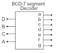
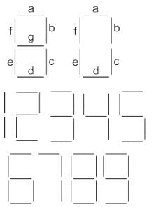
The number of input lines in a common BCD to seven segment decoder is _____.- a)8
- b)2
- c)16
- d)4
Correct answer is option 'D'. Can you explain this answer?
The number of input lines in a common BCD to seven segment decoder is _____.
a)
8
b)
2
c)
16
d)
4
|
|
Sudhir Patel answered |
- In BCD to 7-segment Decoder, the outputs of a digital circuit are often displayed as decimal digits.
- BCD to 7-segment decoder is a combinational circuit that converts a BCD number into signals that are required for the display of the value of that number on a seven-segment display.
- The number of input lines is 4.
Which of the following represents a number of output lines for a decoder with 4 input lines?- a)15
- b)16
- c)17
- d)18
Correct answer is option 'B'. Can you explain this answer?
Which of the following represents a number of output lines for a decoder with 4 input lines?
a)
15
b)
16
c)
17
d)
18
|
|
Sarita Yadav answered |
For n input lined decoder will have 2n output lines.
Which of the following can be represented for decoder?- a)Sequential circuit
- b)Combinational circuit
- c)Logical circuit
- d)None of the mentioned
Correct answer is option 'B'. Can you explain this answer?
Which of the following can be represented for decoder?
a)
Sequential circuit
b)
Combinational circuit
c)
Logical circuit
d)
None of the mentioned
|
|
Yash Patel answered |
Combinational circuit in which output depends only on the state of inputs.
ln the circuit shown the device connected to Y5 can have an address in the range: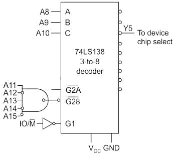
- a)2000 - 20FF
- b)2D00 - 2DFF
- c)2E00 - 2EFF
- d)FD00 - FDFF
Correct answer is option 'D'. Can you explain this answer?
ln the circuit shown the device connected to Y5 can have an address in the range:
a)
2000 - 20FF
b)
2D00 - 2DFF
c)
2E00 - 2EFF
d)
FD00 - FDFF
|
|
Sudhir Patel answered |
Concept:
The simple decoder is shown below:
Addressing is done based on the inputs and their respective logic circuit connected to the address decoders.
Calculation:
In the given question the chip select for Y5 is 101.
A10A9A8 are used for that chip select so A10A9A8 = 101.
A7 ⋯ A0 are initially zeroes and at the final address these will be all 1’s.
To get the active high output for the NAND gate all the inputs must be 1 always.
The total addressing range is shown below:
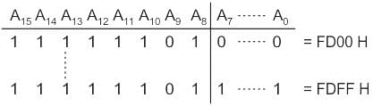
FD00H to FDFFH
Match the following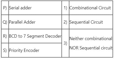
- a)P → 1, Q → 2, R → 1, S → 2
- b)P → 2, Q → 1, R → 1, S → 1
- c)P → 1, Q → 1, R → 3, S → 1
- d)P → 2, Q → 1, R → 3, S → 2
Correct answer is option 'B'. Can you explain this answer?
Match the following
a)
P → 1, Q → 2, R → 1, S → 2
b)
P → 2, Q → 1, R → 1, S → 1
c)
P → 1, Q → 1, R → 3, S → 1
d)
P → 2, Q → 1, R → 3, S → 2
|
|
Sudhir Patel answered |
Sequential circuit :
- Sequential circuits are those circuits whose output depends on present output depends on present input and past output.
- Sequential circuits contains memory elements.
- Sequential circuits are constructed using Flip flops
- examples: Counters, Shift registers, Serial adder
Combinational circuits :
- Combinational circuits are those circuits whose present output depends only on the present input.
- Combinational circuits do not contain memory elements.
- Examples: adders, subtractions, Decoder, Encoder, multiplexers
Combinational circuit: Parallel Adder, BCD to 7 Segment Decoder, Priority Encoder
Sequential circuit: Serial adder,
P → 2, Q → 1, R → 1, S → 1
Which of the following is a decoder IC?- a)7890
- b)8870
- c)4047
- d)4041
Correct answer is option 'B'. Can you explain this answer?
Which of the following is a decoder IC?
a)
7890
b)
8870
c)
4047
d)
4041
|
|
Yash Patel answered |
8870 is a DTMF decoder circuit, which decodes DTMF tune and produces corresponding output.
The discrepancy of 0 output due to all inputs being 0 or D0, being 0 is resolved by using additional input known as ___________- a)Enable
- b)Disable
- c)Strobe
- d)Clock
Correct answer is option 'A'. Can you explain this answer?
The discrepancy of 0 output due to all inputs being 0 or D0, being 0 is resolved by using additional input known as ___________
a)
Enable
b)
Disable
c)
Strobe
d)
Clock
|
|
Sudhir Patel answered |
Such problems are resolved by using enable input, which behaves as active if it gets 0 as input since it is an active-low pin.
Can an encoder be a transducer?- a)Yes
- b)No
- c)May or may not be
- d)Both are not even related slightly
Correct answer is option 'A'. Can you explain this answer?
Can an encoder be a transducer?
a)
Yes
b)
No
c)
May or may not be
d)
Both are not even related slightly
|
|
Sudhir Patel answered |
Of course, a transducer is a device that has the capability to emit data as well as to accept. Transducer converts signal from one form of energy to another.
Invalid BCD can be made to valid BCD by adding with _______________- a)0101
- b)0110
- c)0111
- d)1001
Correct answer is option 'B'. Can you explain this answer?
Invalid BCD can be made to valid BCD by adding with _______________
a)
0101
b)
0110
c)
0111
d)
1001
|
|
Yash Patel answered |
Invalid BCD are numbers greater than 1001, and they can be made valid BCD by adding with 0110.
BCD to seven segment conversion is a ________________- a)Decoding process
- b)Encoding process
- c)Comparing process
- d)None of the mentioned
Correct answer is option 'A'. Can you explain this answer?
BCD to seven segment conversion is a ________________
a)
Decoding process
b)
Encoding process
c)
Comparing process
d)
None of the mentioned
|
|
Sarita Yadav answered |
BCD to seven segment code conversion can be treated as a decoding process.
Decoder is constructed from ________________- a)Inverters
- b)AND gates
- c)Inverters and AND gates
- d)None of the mentioned
Correct answer is option 'C'. Can you explain this answer?
Decoder is constructed from ________________
a)
Inverters
b)
AND gates
c)
Inverters and AND gates
d)
None of the mentioned
|
|
Sarita Yadav answered |
Decoder circuits are constructed from Inverters and AND gates.
Chapter doubts & questions for Encoders & Decoders - Digital Circuits 2025 is part of Electronics and Communication Engineering (ECE) exam preparation. The chapters have been prepared according to the Electronics and Communication Engineering (ECE) exam syllabus. The Chapter doubts & questions, notes, tests & MCQs are made for Electronics and Communication Engineering (ECE) 2025 Exam. Find important definitions, questions, notes, meanings, examples, exercises, MCQs and online tests here.
Chapter doubts & questions of Encoders & Decoders - Digital Circuits in English & Hindi are available as part of Electronics and Communication Engineering (ECE) exam.
Download more important topics, notes, lectures and mock test series for Electronics and Communication Engineering (ECE) Exam by signing up for free.
Digital Circuits
76 videos|175 docs|70 tests
|
|
© EduRev
|
Education Revolution
|


|


Signup on EduRev and stay on top of your study goals
10M+ students crushing their study goals daily