


All Exams >
EmSAT Achieve >
Physics for EmSAT Achieve >
All Questions
All questions of Transformers for EmSAT Achieve Exam
How can eddy current loss be minimised in Transformer?- a)By using iron core
- b)By using air core
- c)By using steel core
- d)By using laminated iron core
Correct answer is option 'D'. Can you explain this answer?
How can eddy current loss be minimised in Transformer?
a)
By using iron core
b)
By using air core
c)
By using steel core
d)
By using laminated iron core

|
Arien Instructors answered |
- Eddy current losses in a transformer are a form of power loss due to the induction of circulating currents in the core material when it is subjected to alternating magnetic fields.
- These losses contribute to the overall inefficiencies in a transformer and generate unwanted heat.
However, there are several strategies to minimize eddy current losses in transformers:
- Laminated Cores:
- The core of the transformer is made from thin sheets of electrical steel, laminated and insulated from each other by a thin layer of insulating material. This construction increases the electrical resistance to the flow of eddy currents perpendicular to the laminations, thereby reducing the magnitude of these currents and the resulting losses.
- The thinner the laminations, the lower the eddy current losses, but this comes with increased manufacturing costs.
- High-quality core material:
- Using high-grade silicon steel, or electrical steel, with specific properties that reduce hysteretic and eddy current losses.
- Silicon steel improves the electrical resistivity of the core material, further reducing the eddy currents.
- Amorphous steel, though more expensive, offers even lower loss characteristics and is used in high-efficiency transformers.
- Silicon steel improves the electrical resistivity of the core material, further reducing the eddy currents.
- Optimal Operating Frequency:
- Eddy current losses increase with the square of the frequency. While this is a limitation in applications with a fixed supply frequency (e.g., 50 Hz or 60 Hz mains power), in applications where the frequency is controllable (such as in some types of electronic transformers), operating at the most efficient frequency can reduce these losses.
- Reduced Core Flux Density:
- Operating the transformer at a lower magnetic flux density can also reduce eddy current losses, as these losses are proportional to the square of the flux density. However, reducing flux density might require a larger core or a different core material to maintain the same level of performance, which could increase costs and physical size.
- Improved Core Design:
- The design of the transformer core can be optimized to reduce pathways for eddy currents.
- This includes both the shape of the core and the arrangement of the laminations. Techniques such as step-lap and cross-lap designs in the lamination stacks can help reduce eddy currents by aligning the magnetic domains more effectively.
- Use of grain-oriented steel laminations:
- The use of grain-oriented (GO) silicon steel, where the magnetic properties are optimized in one direction, can further reduce losses if the grain orientation is aligned with the direction of the magnetic flux.

Energy lost due to hysteresis during each cycle in the core of a transformer working at 50 Hz is 6 J. What will be the power loss due to hysteresis?- a)300 W
- b)200 W
- c)100 W
- d)600 W
Correct answer is option 'A'. Can you explain this answer?
Energy lost due to hysteresis during each cycle in the core of a transformer working at 50 Hz is 6 J. What will be the power loss due to hysteresis?
a)
300 W
b)
200 W
c)
100 W
d)
600 W
|
|
Issa Al Ghafri answered |
Calculation of Power Loss due to Hysteresis:
Given:
Energy lost per cycle = 6 J
Frequency (f) = 50 Hz
Formula:
Power = Energy / Time
Calculation:
- Energy lost per second (Power) = 6 J * 50 Hz = 300 J/s = 300 W
Therefore, the power loss due to hysteresis in the transformer core is 300 W, which corresponds to option 'A'.
Given:
Energy lost per cycle = 6 J
Frequency (f) = 50 Hz
Formula:
Power = Energy / Time
Calculation:
- Energy lost per second (Power) = 6 J * 50 Hz = 300 J/s = 300 W
Therefore, the power loss due to hysteresis in the transformer core is 300 W, which corresponds to option 'A'.
For a 20 - kVA transformer, the iron and copper losses at full load are 300 W and 250 W, respectively. What is the transformer efficiency under full load at unity power factor?- a)48.66%
- b)98.76%
- c)98.52%
- d)97.32%
Correct answer is option 'D'. Can you explain this answer?
For a 20 - kVA transformer, the iron and copper losses at full load are 300 W and 250 W, respectively. What is the transformer efficiency under full load at unity power factor?
a)
48.66%
b)
98.76%
c)
98.52%
d)
97.32%
|
|
Arien Instructors answered |
Given:
kVA rating (kva) = 20
Iron loss (iron_loss) = 300 W
Copper loss (copper_loss) = 250 W
Calculations:
Iron loss (iron_loss) = 300 W
Copper loss (copper_loss) = 250 W
Calculations:
Total Losses:
total_loss = iron_loss + copper_loss
total_loss = 300 W + 250 W
total_loss = 550 W
Apparent Power Output (Sout):
total_loss = 300 W + 250 W
total_loss = 550 W
Apparent Power Output (Sout):
We are considering full load, so Sout is equal to the kVA rating converted to VA.
Sout_va = kva * 1000 (conversion factor from kVA to VA)
Sout_va = 20 kVA * 1000 VA/kVA
Sout_va = 20000 VA
Output Power (Pout):
Sout_va = kva * 1000 (conversion factor from kVA to VA)
Sout_va = 20 kVA * 1000 VA/kVA
Sout_va = 20000 VA
Output Power (Pout):
At unity power factor (unity PF), all the apparent power is transferred as real power (Pout).
Pout_w = Sout_va (since PF = 1)
Pout_w = 20000 VA
Efficiency:
Pout_w = Sout_va (since PF = 1)
Pout_w = 20000 VA
Efficiency:
efficiency = (Pout_w / (Pout_w + total_loss)) * 100
efficiency = (20000 W / (20000 W + 550 W)) * 100
Result:
efficiency = (20000 W / (20000 W + 550 W)) * 100
Result:
efficiency ≈ 97.32%
Therefore, the efficiency of the 20 kVA transformer at full load and unity power factor is approximately 97.32%.
Therefore, the efficiency of the 20 kVA transformer at full load and unity power factor is approximately 97.32%.
Which is to be short circuited on performing short circuit test on a transformer?- a)Low Voltage Side
- b)High Voltage Side
- c)Primary side
- d)Secondary side
Correct answer is option 'A'. Can you explain this answer?
Which is to be short circuited on performing short circuit test on a transformer?
a)
Low Voltage Side
b)
High Voltage Side
c)
Primary side
d)
Secondary side
|
|
Safiya Omar Al Haddad answered |
Short Circuit Test on a Transformer
Short circuit test is performed on a transformer to determine its impedance and losses under short circuit conditions. When the short circuit test is conducted, the low voltage side of the transformer is to be short circuited.
Reason for Short Circuiting Low Voltage Side
- The low voltage side of the transformer is short circuited because the primary winding on this side has fewer turns compared to the high voltage side. This means that the current flowing through the primary winding is higher, leading to a more significant short circuit current.
- Short circuiting the low voltage side allows for a more accurate measurement of the impedance and losses of the transformer under short circuit conditions.
- The short circuit test helps in determining the equivalent circuit parameters of the transformer, such as the resistance and reactance of the windings. These parameters are crucial in understanding the performance of the transformer under different operating conditions.
Impact of Short Circuit Test
- Performing the short circuit test on the low voltage side helps in assessing the transformer's ability to withstand short circuit conditions and ensures its reliability and safety.
- The test also helps in determining the efficiency of the transformer and identifying any potential issues that may arise during short circuit events.
In conclusion, short circuit test on a transformer involves short circuiting the low voltage side to accurately measure the impedance and losses of the transformer under short circuit conditions. This test is essential for evaluating the transformer's performance and ensuring its safe operation.
In order to minimize the inrush current in a single-phase transformer, the supply switch should be closed at the instant when:- a)supply voltage is 1/2 times the maximum voltage
- b)supply voltage is 1/√2 times the maximum voltage
- c)supply voltage is maximum
- d)supply voltage is zero
Correct answer is option 'C'. Can you explain this answer?
In order to minimize the inrush current in a single-phase transformer, the supply switch should be closed at the instant when:
a)
supply voltage is 1/2 times the maximum voltage
b)
supply voltage is 1/√2 times the maximum voltage
c)
supply voltage is maximum
d)
supply voltage is zero
|
|
Arien Instructors answered |
- Magnetizing inrush current in transformer is the current which is drawn by a transformer at the time of energizing it.
- To have minimum inrush current in the transformer the switch-on instant should be at maximum input voltage
- This inrush current is transient in nature and exists for few milliseconds.
- The inrush current may be up to 10 times higher than the normal rated current of the transformer.
- Although the magnitude of inrush current is high it generally does not create any permanent fault in the transformer as it exists for a very small time.
- But still, inrush current in a power transformer is a problem, because it interferes with the operation of circuits as they have been designed to function.
- Some effects of high inrush current include nuisance fuse or breaker interruptions, as well as arcing and failure of primary circuit components, such as switches. Another side effect of high inrush is the injection of noise.
A transformer has positive voltage regulation when its load power factor is:- a)zero
- b)leading
- c)lagging
- d)unity
Correct answer is option 'C'. Can you explain this answer?
A transformer has positive voltage regulation when its load power factor is:
a)
zero
b)
leading
c)
lagging
d)
unity
|
|
Arien Instructors answered |
Voltage regulation for the transformer is given by the ratio of change in secondary terminal voltage from no load to full load to no load secondary voltage.
Voltage regulation =E2−V2 / E2
It can also be expressed as,
Regulation =I2R02cosϕ2±I2X02sinϕ2 / E2
+ sign is used for lagging loads
Under load conditions, the efficiency of two identical transformers can be measured by:- a)High potential test
- b)Blocked Rotor test
- c)Sumpner’s test
- d)No load test
Correct answer is option 'C'. Can you explain this answer?
Under load conditions, the efficiency of two identical transformers can be measured by:
a)
High potential test
b)
Blocked Rotor test
c)
Sumpner’s test
d)
No load test
|
|
Arien Instructors answered |
- The efficiency of two identical transformers under load conditions can be determined by performing a back-to-back test.
- In this test, the two transformers are connected in parallel, and the primary windings of both transformers are connected to the same source.
- The secondary windings are then connected to a load.
- The efficiency of two identical transformers under load conditions can be measured and compared using a method known as the back-to-back test, also referred to as the Sumpner's test.
- This method is particularly effective because it allows the assessment of the transformer efficiency under load conditions without the necessity to supply the full load power from the external circuit, thus saving energy and reducing the requirements for high power sources for testing.
- Advantages:
- Energy-efficient, as most of the load power is circulated internally.
- Reduced requirements for a high-capacity power source for testing under full-load conditions.
- Allows assessment of efficiency under simulated full-load conditions without the need for actual full-power dissipation.
- Limitations:
- It mainly provides information on steady-state efficiency and losses, without insights into transient behaviors or other dynamic characteristics.
- Accurate for similar types of transformers but might not fully replicate all operational conditions.
A step-up transformer converts ________ into a ________.- a)low voltage at low current, high voltage at high current
- b)high voltage at low current, low voltage at high current
- c)high voltage at high current, low voltage at low current
- d)low voltage at high current, high voltage at low current
Correct answer is option 'D'. Can you explain this answer?
A step-up transformer converts ________ into a ________.
a)
low voltage at low current, high voltage at high current
b)
high voltage at low current, low voltage at high current
c)
high voltage at high current, low voltage at low current
d)
low voltage at high current, high voltage at low current
|
|
Arien Instructors answered |
- As in the step-up transformer, the number of coils in the secondary coil is more than that in the primary coil. So the electrical potential increases.
- A step-up transformer converts low voltage at high current into a high voltage at low current. So option 4 is correct.
Generally the no-load losses of an electrical machine is represented in its equivalent circuit by a- a)Parallel resistance with a low value
- b)Series resistance with a low value
- c)Parallel resistance with a high value
- d)Series resistance with a high value
Correct answer is option 'C'. Can you explain this answer?
Generally the no-load losses of an electrical machine is represented in its equivalent circuit by a
a)
Parallel resistance with a low value
b)
Series resistance with a low value
c)
Parallel resistance with a high value
d)
Series resistance with a high value
|
|
Arien Instructors answered |
When the load is not connected to the electric machine, the machine draws a low value of current to keep the machine active or running
- The current which is taken by the machine is called no-load current
- Current is drawn by the core of the machine
- The equivalent circuit is represented by a high value of resistance in parallel.
- The power factor of the machine will be very low.
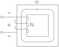
A single-phase 111-V, 50-Hz supply is connected to a coil with 200 turns of a coil-core assembly as shown in the given figure. Find the magnitude of maximum flux in the core.
- a)10 mWb
- b)2.5 mWb
- c)1 mWb
- d)25 mWb
Correct answer is option 'B'. Can you explain this answer?
A single-phase 111-V, 50-Hz supply is connected to a coil with 200 turns of a coil-core assembly as shown in the given figure. Find the magnitude of maximum flux in the core.
a)
10 mWb
b)
2.5 mWb
c)
1 mWb
d)
25 mWb
|
|
Arien Instructors answered |
E = 111 V, f = 50 Hz, N = 200
111 = 4.44 × 50 × 200 × ϕm
ϕm = 111 / (4.44 × 50 × 200)
= 2.5 mWb
Chapter doubts & questions for Transformers - Physics for EmSAT Achieve 2025 is part of EmSAT Achieve exam preparation. The chapters have been prepared according to the EmSAT Achieve exam syllabus. The Chapter doubts & questions, notes, tests & MCQs are made for EmSAT Achieve 2025 Exam. Find important definitions, questions, notes, meanings, examples, exercises, MCQs and online tests here.
Chapter doubts & questions of Transformers - Physics for EmSAT Achieve in English & Hindi are available as part of EmSAT Achieve exam.
Download more important topics, notes, lectures and mock test series for EmSAT Achieve Exam by signing up for free.
Physics for EmSAT Achieve
208 videos|329 docs|212 tests
|
|
© EduRev
|
Education Revolution
|


|


Signup to see your scores
go up
within 7 days!
within 7 days!
Takes less than 10 seconds to signup