


All Exams >
Civil Engineering (CE) >
GATE Civil Engineering (CE) 2026 Mock Test Series >
All Questions
All questions of Design of Steel Structures for Civil Engineering (CE) Exam


For an I-beam, shape factor is 1.12. The factor of safety in bending is 1.5. if the allowable stress is increased by 20% for wind and earthquake loads, then the load factor is - a)1.10
- b)1.25
- c)1.35
- d)1.40
Correct answer is option 'D'. Can you explain this answer?
For an I-beam, shape factor is 1.12. The factor of safety in bending is 1.5. if the allowable stress is increased by 20% for wind and earthquake loads, then the load factor is
a)
1.10
b)
1.25
c)
1.35
d)
1.40
|
|
Sanvi Kapoor answered |
With increase in allowable stress, the factor of safety will reduce to 1.5/1.2 = 1.25.
∴ Load Factor = FS x shape factor
= 1.25 x 1.12
= 1.40
A steel plate is 300 mm wide and 10 mm thick. A rivet of nominal diameter 18 mm is driven. The net sectional area of the plate is- a)1800 mm2
- b)2805 mm2
- c)2820 mm2
- d)3242 mm2
Correct answer is option 'B'. Can you explain this answer?
A steel plate is 300 mm wide and 10 mm thick. A rivet of nominal diameter 18 mm is driven. The net sectional area of the plate is
a)
1800 mm2
b)
2805 mm2
c)
2820 mm2
d)
3242 mm2

|
Sankar Rane answered |
Net sectional area of the plate is given by,
Anet = (B - nd) x t
= [300-1 x (18 + 1.5)] x 10
= 2805 mm2
Anet = (B - nd) x t
= [300-1 x (18 + 1.5)] x 10
= 2805 mm2
What is the ratio of the yield stress in power driven shop rivets relative to the permissible bearing stress of mild steel?- a)1.0
- b)0.8
- c)0.6
- d)0.4
Correct answer is option 'B'. Can you explain this answer?
What is the ratio of the yield stress in power driven shop rivets relative to the permissible bearing stress of mild steel?
a)
1.0
b)
0.8
c)
0.6
d)
0.4

|
Anshul Kumar answered |
The yield stress in power drive rivets is 200MPa and bearing stress of mild steel is 250MPa.
Thus, ratio
= 200/250
=0.8
Thus, ratio
= 200/250
=0.8
The maximum longitudinal pitch allowed in bolted joints of tension members is- a)16 times the diameter of the bolt
- b)32 times the diameter of the bolt
- c)16 times the thickness of the plate
- d)32 times the thickness of the plate
Correct answer is option 'C'. Can you explain this answer?
The maximum longitudinal pitch allowed in bolted joints of tension members is
a)
16 times the diameter of the bolt
b)
32 times the diameter of the bolt
c)
16 times the thickness of the plate
d)
32 times the thickness of the plate
|
|
Devansh Banerjee answered |
Maximum longitudinal pitch in bolted joints of tension members
The maximum longitudinal pitch allowed in bolted joints of tension members is an important consideration in the design of steel structures. It is defined as the distance between the centers of adjacent bolts along the direction of the applied load.
Formula
The maximum longitudinal pitch can be calculated using the following formula:
Maximum longitudinal pitch = 16 x t
Where t is the thickness of the plate.
Explanation
The maximum longitudinal pitch is limited to prevent the occurrence of excessive deformation, bending, or buckling of the connected plates. The value of 16 times the thickness of the plate is based on experimental and theoretical studies of bolted connections, and it has been found to provide a safe and reliable limit for most practical situations.
The maximum longitudinal pitch applies to tension members, which are members that are subjected to axial tension forces. These members include bolts, rods, cables, and other structural elements that carry tensile loads.
Conclusion
In conclusion, the maximum longitudinal pitch allowed in bolted joints of tension members is 16 times the thickness of the plate. This value should be used in the design of bolted connections to ensure the structural integrity and safety of steel structures.
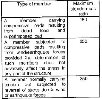
A tension member, if subjected to possible reversal of stress due to wind or earthquake the slenderness ratio of the member should not exceed- a)180
- b)300
- c)250
- d)350
Correct answer is option 'D'. Can you explain this answer?
A tension member, if subjected to possible reversal of stress due to wind or earthquake the slenderness ratio of the member should not exceed
a)
180
b)
300
c)
250
d)
350

|
Sandeep Sen answered |
Slenderness Ratio for Tension Members
A tension member in a structure is a component that is designed to resist axial tensile forces. Examples of tension members include cables, rods, and tie-rods. When designing a tension member, one of the important considerations is its slenderness ratio.
Definition of Slenderness Ratio
Slenderness ratio is defined as the ratio of the effective length of a member to its least radius of gyration. It is a measure of the member's ability to resist buckling under axial compression. For a tension member, the slenderness ratio is still an important factor to consider, especially if there is a possibility of reversal of stress due to wind or earthquake.
Limitation of Slenderness Ratio for Tension Members
The maximum slenderness ratio for a tension member is limited to prevent buckling under axial compression. However, when a tension member is subjected to possible reversal of stress due to wind or earthquake, the slenderness ratio should not exceed a certain limit. According to the Indian Standard Code of Practice for Structural Steel, the maximum slenderness ratio for tension members subjected to possible reversal of stress is 350.
Conclusion
In conclusion, when designing a tension member in a structure, it is important to consider its slenderness ratio. For tension members that may be subjected to reversal of stress due to wind or earthquake, the maximum slenderness ratio should not exceed 350, according to the Indian Standard Code of Practice for Structural Steel.
A tie member consists of ISA 100 × 75 × 8 longer leg is connected to a gusset plate. The gross cross sectional area of connected and unconnected leg are _______ mm2 respectively.- a)768 and 568
- b)344 and 288
- c)976 and 654
- d)1206 and 743
Correct answer is option 'A'. Can you explain this answer?
A tie member consists of ISA 100 × 75 × 8 longer leg is connected to a gusset plate. The gross cross sectional area of connected and unconnected leg are _______ mm2 respectively.
a)
768 and 568
b)
344 and 288
c)
976 and 654
d)
1206 and 743
|
|
Muskaan Sen answered |
Understanding the Tie Member
A tie member, specifically an ISA (Indian Standard Angle) with dimensions 100 × 75 × 8, has specific properties that need to be analyzed for its cross-sectional area.
Dimensions Breakdown
- Long leg: 100 mm
- Short leg: 75 mm
- Thickness: 8 mm
Gross Cross-Sectional Area Calculation
To calculate the gross cross-sectional areas of the connected and unconnected legs, we use the following formulas:
- Area of the long leg (connected):
- Area = Length × Thickness
- Area = 100 mm × 8 mm = 800 mm²
- Area of the short leg (unconnected):
- Area = Length × Thickness
- Area = 75 mm × 8 mm = 600 mm²
However, the gross area also accounts for the reduction due to the corner cut-out, which is approximately 32 mm² for each leg.
Final Areas Adjustment
- Connected leg (long leg):
- Gross Area = 800 mm² - 32 mm² = 768 mm²
- Unconnected leg (short leg):
- Gross Area = 600 mm² - 32 mm² = 568 mm²
Conclusion
Thus, the gross cross-sectional area of the connected and unconnected leg are 768 mm² and 568 mm², respectively. This aligns with option 'A', confirming it as the correct answer.
The order of elongation which a specimen of mild steel undergoes before fracture is- a)0.1%
- b)1%
- c)10%
- d)100%
Correct answer is option 'C'. Can you explain this answer?
The order of elongation which a specimen of mild steel undergoes before fracture is
a)
0.1%
b)
1%
c)
10%
d)
100%
|
|
Hiral Sharma answered |
For mild steel
(i) Proportional limit (190 - 220) N/mm2
(ii) Yield strength (230 - 250) N/mm2
(iii) Ultimate strength (410 - 530) N/mm2
(iv) Fracture strength (250 - 300) N/mm2
(v) Elongation at fracture (23 - 35)% Thus the order of elongation is 10%
(i) Proportional limit (190 - 220) N/mm2
(ii) Yield strength (230 - 250) N/mm2
(iii) Ultimate strength (410 - 530) N/mm2
(iv) Fracture strength (250 - 300) N/mm2
(v) Elongation at fracture (23 - 35)% Thus the order of elongation is 10%
The plastic section modulus for a rectangular section of width b and depth d is- a)bd2/3
- b)bd2/4
- c)bd2/6
- d)bd2/12
Correct answer is option 'B'. Can you explain this answer?
The plastic section modulus for a rectangular section of width b and depth d is
a)
bd2/3
b)
bd2/4
c)
bd2/6
d)
bd2/12
|
|
Kavya Mehta answered |
Plastic Section Modulus for Rectangular Section
Plastic section modulus is used to calculate the bending capacity of a cross-section of a structural member. In the case of a rectangular section, the plastic section modulus is given by:
Zp = bd2/4
where b is the width of the section and d is the depth of the section.
Explanation of the Formula
To understand the formula for plastic section modulus of a rectangular section, let's consider a beam that is subject to bending. When a beam is subjected to bending, the top and bottom fibers of the beam are in compression and tension, respectively. At some point, the stress in the extreme fibers reaches the yield strength of the material, and plastic deformation begins to occur.
The plastic section modulus is a measure of the ability of a cross-section to resist plastic deformation. It is defined as the ratio of the moment of inertia of the cross-section to the distance from the extreme fiber to the neutral axis. For a rectangular section, the distance from the extreme fiber to the neutral axis is equal to half the depth of the section, i.e., d/2.
The moment of inertia of a rectangular section is given by:
I = bd3/12
Substituting this expression into the formula for plastic section modulus gives:
Zp = I/(d/2) = bd3/12/(d/2) = bd2/4
Therefore, the plastic section modulus for a rectangular section of width b and depth d is given by:
Zp = bd2/4
Conclusion
The plastic section modulus for a rectangular section is an important parameter in the design of structural members. The formula for plastic section modulus of a rectangular section is derived based on the moment of inertia of the section and the distance from the extreme fiber to the neutral axis. The plastic section modulus is a measure of the ability of a cross-section to resist plastic deformation and is used to calculate the bending capacity of a structural member.
Which one of the following stresses is independent of yield stress as a permissible stress for steel members?- a)Axial tensile stress
- b)Maximum shear stress
- c)Bearing stress
- d)Stress in slab base
Correct answer is option 'D'. Can you explain this answer?
Which one of the following stresses is independent of yield stress as a permissible stress for steel members?
a)
Axial tensile stress
b)
Maximum shear stress
c)
Bearing stress
d)
Stress in slab base
|
|
Neha Mukherjee answered |
Permissible values
Axial tensile stress = 0.6fy
Bearing stress = 0.75fy
Maximum shear stress = 0.45fy
Stress in slab base = 185 MPa for all type of steels.
Axial tensile stress = 0.6fy
Bearing stress = 0.75fy
Maximum shear stress = 0.45fy
Stress in slab base = 185 MPa for all type of steels.
Consider the following statements regarding tensile test diagrams for carbon steels with varying carbon contents:
As the carbon content increases
1. the ultimate strength of steel decreases
2. the elongation before fracture increases
3. the ductility of the metal decreases
4. the ultimate strength increasesWhich of these statements are correct?- a)3 and 4
- b)1 and 3
- c)1,2 and 3
- d)1 and 2
Correct answer is option 'A'. Can you explain this answer?
Consider the following statements regarding tensile test diagrams for carbon steels with varying carbon contents:
As the carbon content increases
1. the ultimate strength of steel decreases
2. the elongation before fracture increases
3. the ductility of the metal decreases
4. the ultimate strength increases
As the carbon content increases
1. the ultimate strength of steel decreases
2. the elongation before fracture increases
3. the ductility of the metal decreases
4. the ultimate strength increases
Which of these statements are correct?
a)
3 and 4
b)
1 and 3
c)
1,2 and 3
d)
1 and 2
|
|
Mehul Choudhury answered |
Carbon has the maximum influence on the mechanical properties of steel. Iron-carbon alloys containing up to 2 per cent carbon are called carbon steel while those having more than 2% are called cast steel. With increase in carbon the tensile strength of steel increases but the ductility falls.
The allowable shear stress in the web of mild steel beam decreases withwhere 'h' is height and ‘t is thickness- a)decrease in h/t ratio
- b)increase in h/t ratio
- c)decrease in thickness
- d)increase in height
Correct answer is option 'B'. Can you explain this answer?
The allowable shear stress in the web of mild steel beam decreases with
where 'h' is height and ‘t is thickness
a)
decrease in h/t ratio
b)
increase in h/t ratio
c)
decrease in thickness
d)
increase in height
|
|
Meghana Desai answered |
According to I.S. 800 - 1984 the maximum permissible shear stress should not exceed the value of  The permissible average shear stress
  on a web whose depth does not exceed 85 times its thickness, is equal to
The allowable shear stress in the web of a mild steel beam decreases with increase in hit ratio. And for same h/t ratio allowable shear stress decreases with increase in spacing of stiffeners.
The permissible average shear stress on a web whose depth does not exceed 85 times its thickness, is equal to The allowable shear stress in the web of a mild steel beam decreases with increase in hit ratio. And for same h/t ratio allowable shear stress decreases with increase in spacing of stiffeners.
Slenderness ratio of the splices for compression members is- a)0
- b)145
- c)180
- d)350
Correct answer is option 'A'. Can you explain this answer?
Slenderness ratio of the splices for compression members is
a)
0
b)
145
c)
180
d)
350
|
|
Tanishq Menon answered |
Splices used in compression members are assumed to act as short columns with zero slender ness ratio.
The plastic hinge formed in a collapse mechanism are 4 and the indeterminacy is 3. The collapse is- a)Partial
- b)Complete
- c)Over complete
- d)Under complete
Correct answer is option 'B'. Can you explain this answer?
The plastic hinge formed in a collapse mechanism are 4 and the indeterminacy is 3. The collapse is
a)
Partial
b)
Complete
c)
Over complete
d)
Under complete
|
|
Navya Kaur answered |
If the number of plastic hinges in the collapse mechanism are less than (r + 1) the collapse is called partial collapse. In such a case, part of the structure may fail making it useless as a whole. If the number of plastic hinges in the collapse mechanism are (r + 1) the collapse is called complete collapse. Such a mechanism has only one degree of freedom. If the number of plastic hinges developed are more than (r + 1), the collapse is called over complete collapse. In such a case there are two or more mechanisms for which the corresponding value of the load is the same, this load value being the actual coljapse load.
If the degree of indeterminacy is r, and the number of plastic hinges developed is N then,
N < (r + 1) Partial collapse
N = r + 1 Complete collapse .
N > r + 1 Overcomplete collapse
If the degree of indeterminacy is r, and the number of plastic hinges developed is N then,
N < (r + 1) Partial collapse
N = r + 1 Complete collapse .
N > r + 1 Overcomplete collapse
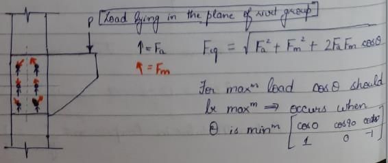
When the axis of load lies in the plane of rivet group, then the most heavily loaded rivet will be the one which.where, Fa is the load shared by each rivet due to axial load and Fm is the shearing load due to moment in any rivet- a)is at the CG of the rivet group
- b)is at the minimum distance from CG of the rivet group
- c)gives the maximum angle between the two forces Fa and Fm
- d)gives the minimum angle between the two forces Fa and Fm
Correct answer is option 'D'. Can you explain this answer?
When the axis of load lies in the plane of rivet group, then the most heavily loaded rivet will be the one which.
where, Fa is the load shared by each rivet due to axial load and Fm is the shearing load due to moment in any rivet
a)
is at the CG of the rivet group
b)
is at the minimum distance from CG of the rivet group
c)
gives the maximum angle between the two forces Fa and Fm
d)
gives the minimum angle between the two forces Fa and Fm
|
|
Pallabi Kulkarni answered |
What is the permissible tensile stress in bolts used for column bases (fy is the yield stress of the steel)?- a)120N/mm2
- b)150N/mm2
- c)0.6fy
- d)0.4fy
Correct answer is option 'A'. Can you explain this answer?
What is the permissible tensile stress in bolts used for column bases (fy is the yield stress of the steel)?
a)
120N/mm2
b)
150N/mm2
c)
0.6fy
d)
0.4fy
|
|
Snehal Tiwari answered |
Permissible tensile stresses in bolts used for column bases is 120 N/mm2.
An equal angle of area A has been attached to the support by means of a lug angle. If allowable stress in tension is f, what is the load carrying capacity of the member?- a)0.5fA
- b)0.85fA
- c)0.9fA
- d)1.0fA
Correct answer is option 'D'. Can you explain this answer?
An equal angle of area A has been attached to the support by means of a lug angle. If allowable stress in tension is f, what is the load carrying capacity of the member?
a)
0.5fA
b)
0.85fA
c)
0.9fA
d)
1.0fA
|
|
Pankaj Kapoor answered |
Strength of member = allowable tensile stress x
Net area of the angle
Net area = Gross Area - deduction for holes.
Net area of the angle
Net area = Gross Area - deduction for holes.
A cantilever arm is to be attached to a column. Which one among the following is the best connection?- a)Framed connection
- b)Seated connection
- c)Stiffened seated connection
- d)End plate connection
Correct answer is option 'D'. Can you explain this answer?
A cantilever arm is to be attached to a column. Which one among the following is the best connection?
a)
Framed connection
b)
Seated connection
c)
Stiffened seated connection
d)
End plate connection
|
|
Tanishq Rane answered |
The beam column connections expected to resist and transfer end reactions only are termed as shear connections or flexible connections. These permit free rotation of the beam end and do not have any moment restraint. Bracket connections, seat connections (unstiffened and stiffened) and framed connections are of flexible type.
The other type of connections which do not permit any relative rotation between the beam and column and are expected to resist moment in addition to end reactions are termed as moment connections or rigid connections. For cantilever arm both moment and end reaction is to be transferred without rotation and therefore rigid connections would be the best choice. Clip angle connection, split beam connection and bracket connection (end plate connection) are rigid connections.
The other type of connections which do not permit any relative rotation between the beam and column and are expected to resist moment in addition to end reactions are termed as moment connections or rigid connections. For cantilever arm both moment and end reaction is to be transferred without rotation and therefore rigid connections would be the best choice. Clip angle connection, split beam connection and bracket connection (end plate connection) are rigid connections.
A plate used for connecting two or more structural members intersecting each other is termed as- a)Template
- b)Baseplate
- c)Gusset plate
- d)Shoe plate
Correct answer is option 'C'. Can you explain this answer?
A plate used for connecting two or more structural members intersecting each other is termed as
a)
Template
b)
Baseplate
c)
Gusset plate
d)
Shoe plate
|
|
Samridhi Choudhary answered |
Base plates are provided to distribute the load of a column on greater area.
Failure of tension member is considered when either of following statement is true
1. Excessive elongation in member.
2. Rupture of critical section.
3. Buckling of member.
4. Shear block failure of end connection.- a)1, 2 and 3
- b)2, 3 and 4
- c)1, 3 and 4
- d)1, 2 and 4
Correct answer is option 'D'. Can you explain this answer?
Failure of tension member is considered when either of following statement is true
1. Excessive elongation in member.
2. Rupture of critical section.
3. Buckling of member.
4. Shear block failure of end connection.
1. Excessive elongation in member.
2. Rupture of critical section.
3. Buckling of member.
4. Shear block failure of end connection.
a)
1, 2 and 3
b)
2, 3 and 4
c)
1, 3 and 4
d)
1, 2 and 4
|
|
Sakshi Basak answered |
The three criterion for failure has been considered in new code. Buckling takes place in compression members and not in tension members.
Consider the following statements:
Lug angles are used to
1. increase the lengths of the end connections of angle section.
2. decrease the lengths of the end connections of angle section.
3. increase the lengths of the end connections of channel section.
4. decrease the lengths of the end connections of channel section.Which of these statements are correct?- a)1 and 2
- b)2 and 4
- c)1,3 and 4
- d)1, 2 and 3
Correct answer is option 'B'. Can you explain this answer?
Consider the following statements:
Lug angles are used to
1. increase the lengths of the end connections of angle section.
2. decrease the lengths of the end connections of angle section.
3. increase the lengths of the end connections of channel section.
4. decrease the lengths of the end connections of channel section.
Lug angles are used to
1. increase the lengths of the end connections of angle section.
2. decrease the lengths of the end connections of angle section.
3. increase the lengths of the end connections of channel section.
4. decrease the lengths of the end connections of channel section.
Which of these statements are correct?
a)
1 and 2
b)
2 and 4
c)
1,3 and 4
d)
1, 2 and 3
|
|
Shilpa Pillai answered |
Lug angles are sometimes used to reduce the length of the connections. However their main purpose is to accommodate more number of rivets so that size of the gusset plate may be reduced.
According to IS Specifications, the maximum pitch of rivets in compression is
(where t is thickness of thinnest outside plate or angle)
- a)lesser of 200 mm and 12 t
- b)lesser of 200 mm and 16 t
- c)lesser of 300 mm and 32 t
- d)lesser of 300 mm and 24 t
Correct answer is option 'A'. Can you explain this answer?
According to IS Specifications, the maximum pitch of rivets in compression is
(where t is thickness of thinnest outside plate or angle)
a)
lesser of 200 mm and 12 t
b)
lesser of 200 mm and 16 t
c)
lesser of 300 mm and 32 t
d)
lesser of 300 mm and 24 t
|
|
Hiral Sharma answered |
Maximum pitch of rivets in compression = 12t or 200 mm whichever is less
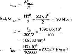
A cantilever steel beam of 3 m span carries a uniformly distributed load of 20 kN/m inclusive of self-weight. The beam comprises of ISLB200@198 N/m, flange = 100 mm x 7.3 mm; web thickness = 5.4 mm; Ixx= 1696.6 cm4; Iyy = 115.4 cm4. What is the maximum bending stress in the beam ?- a)132.62 N/mm2
- b)530.47 N/mm2
- c)1949.74 N/mm2
- d)3899.48 N/mm2
Correct answer is option 'B'. Can you explain this answer?
A cantilever steel beam of 3 m span carries a uniformly distributed load of 20 kN/m inclusive of self-weight. The beam comprises of ISLB200@198 N/m, flange = 100 mm x 7.3 mm; web thickness = 5.4 mm; Ixx= 1696.6 cm4; Iyy = 115.4 cm4. What is the maximum bending stress in the beam ?
a)
132.62 N/mm2
b)
530.47 N/mm2
c)
1949.74 N/mm2
d)
3899.48 N/mm2
|
|
Prashanth Mehra answered |
The maximum bending stress is given by,
The thickness of lacing bars for single lacing, system should not be less thanwhere l = length between the inner end of connections.- a)l/40
- b)l/50
- c)l/60
- d)l/70
Correct answer is option 'A'. Can you explain this answer?
The thickness of lacing bars for single lacing, system should not be less than
where l = length between the inner end of connections.
a)
l/40
b)
l/50
c)
l/60
d)
l/70
|
|
Swara Gupta answered |
Minimum thickness of lacing bars,
 for single lacing
 for double lacing riveted or welded at intersection.
for single lacing for double lacing riveted or welded at intersection.In a simply supported beam of span l, each end is restrained against torsion, compression flange being unrestrained. According to IS : 800, the effective length of the compression flange will be equal to- a)l
- b)0.85l
- c)0.75l
- d)0.70l
Correct answer is option 'A'. Can you explain this answer?
In a simply supported beam of span l, each end is restrained against torsion, compression flange being unrestrained. According to IS : 800, the effective length of the compression flange will be equal to
a)
l
b)
0.85l
c)
0.75l
d)
0.70l
|
|
Rajeev Menon answered |
a) l. According to IS:800 (Indian Standard: Code of Practice for General Construction in Steel), the effective length of the compression flange of a simply supported beam of span l, with each end restrained against torsion and the compression flange unrestrained, is equal to l. The effective length of the compression flange is used to calculate the design moment of the beam and the size of the compression flange required to resist the applied loads. The effective length is based on the assumption that the compression flange is able to develop its full strength and that the beam is able to resist the applied loads without buckling. The effective length may be adjusted based on the specific conditions of the beam and the applied loads.
Which of the following is not a compression member?- a)Strut
- b)Tie
- c)Rafter
- d)Boom
Correct answer is option 'B'. Can you explain this answer?
Which of the following is not a compression member?
a)
Strut
b)
Tie
c)
Rafter
d)
Boom
|
|
Shalini Deshpande answered |
Strut is a compression member used in the roof truss and bracing.
Rafter or principal rafter is a top chord member in a roof truss.
Boom is the principal compression member in a crane.
Tie rods are sag rods provided at the crown of truss used in industrial sheds. These cut as tension members and resist the tangential components from the two sides of roof truss.
Rafter or principal rafter is a top chord member in a roof truss.
Boom is the principal compression member in a crane.
Tie rods are sag rods provided at the crown of truss used in industrial sheds. These cut as tension members and resist the tangential components from the two sides of roof truss.
Which one among the following is the correct ratio of effective length to actual length of a discontinuous angle strut, if ends are welded?- a)0.65
- b)0.85
- c)1.0 .
- d)1.2
Correct answer is option 'B'. Can you explain this answer?
Which one among the following is the correct ratio of effective length to actual length of a discontinuous angle strut, if ends are welded?
a)
0.65
b)
0.85
c)
1.0 .
d)
1.2
|
|
Aniket Mehta answered |
For single angle discontinuous,
(i) One rivet or bolt - Effective length is the distance between the centres of end fastenings
(ii) Two or more rivets or welding - Effective length is 0.85 times the distance between node points.
(i) One rivet or bolt - Effective length is the distance between the centres of end fastenings
(ii) Two or more rivets or welding - Effective length is 0.85 times the distance between node points.
If the thickness of plate to be connected by a rivet is 16 mm, then suitable size of rivet as per Unwin’s formula will be- a)16 mm
- b)20 mm
- c)24 mm
- d)27 mm
Correct answer is option 'C'. Can you explain this answer?
If the thickness of plate to be connected by a rivet is 16 mm, then suitable size of rivet as per Unwin’s formula will be
a)
16 mm
b)
20 mm
c)
24 mm
d)
27 mm
|
|
Sankar Dasgupta answered |
According to Unwin’s formula nominal diameter of rivet is given by,
What is the number of plastic hinges formed if an indeterminate beam with redundancy R is to become determinate?- a)R - 1
- b)R
- c)R + 1
- d)R + 2
Correct answer is option 'B'. Can you explain this answer?
What is the number of plastic hinges formed if an indeterminate beam with redundancy R is to become determinate?
a)
R - 1
b)
R
c)
R + 1
d)
R + 2
|
|
Lakshmi Datta answered |
The number of plastic hinges required to make an indeterminate beam determinate is R where R is the degree of redundancy. However, for the complete collapse of the beam (R + 1) plastic hinges will be required.
As per IS: 800. The maximum bending moment for design of purlins can be taken as- a)WL/6
- b)WL/8
- c)WL/10
- d)WL/12
Correct answer is option 'C'. Can you explain this answer?
As per IS: 800. The maximum bending moment for design of purlins can be taken as
a)
WL/6
b)
WL/8
c)
WL/10
d)
WL/12
|
|
Abhay Kapoor answered |
Design of Purlins as per IS: 800
IS: 800 is the Indian Standard code for general construction in steel. It provides guidelines for the design of steel structures including purlins.
Purlins are horizontal members that support roof covering and transfer loads to the primary frame. The maximum bending moment is an important parameter for the design of purlins.
Formula for Maximum Bending Moment
The maximum bending moment for design of purlins can be calculated using the following formula:
Mmax = WL/10
where,
Mmax = maximum bending moment
W = total weight of roofing material per unit length (including self-weight)
L = span of purlin
Explanation
The maximum bending moment for design of purlins is calculated based on the weight of the roofing material per unit length and the span of the purlin.
The formula Mmax = WL/10 indicates that the maximum bending moment is equal to one-tenth of the total weight of the roofing material per unit length multiplied by the span of the purlin.
Option C, WL/10, is the correct answer as per IS: 800.
In case of single angles in tension connected by one leg only, the net effective area as per IS : 800 is
Where a is net sectional area of connected leg and b is area of the outstanding leg.- a)gross area-area of holes
- b)

- c)

- d)

Correct answer is option 'B'. Can you explain this answer?
In case of single angles in tension connected by one leg only, the net effective area as per IS : 800 is
Where a is net sectional area of connected leg and b is area of the outstanding leg.
Where a is net sectional area of connected leg and b is area of the outstanding leg.
a)
gross area-area of holes
b)
c)
d)
|
|
Madhurima Banerjee answered |

Consider the following statements in respect of design of web and flange splices
1. Flange splice shall be designed for actual BM at the section
2. Flange splice shall be designed to resist the actual shear at the section
3. Web splice shall be designed to resist the actual shear at the section
4. Web splice shall be designed for actual BM
Which of these statements are correct- a)1 and 3
- b)1 and 4
- c)2 and 4
- d)1, 3 and 4
Correct answer is option 'A'. Can you explain this answer?
Consider the following statements in respect of design of web and flange splices
1. Flange splice shall be designed for actual BM at the section
2. Flange splice shall be designed to resist the actual shear at the section
3. Web splice shall be designed to resist the actual shear at the section
4. Web splice shall be designed for actual BM
Which of these statements are correct
1. Flange splice shall be designed for actual BM at the section
2. Flange splice shall be designed to resist the actual shear at the section
3. Web splice shall be designed to resist the actual shear at the section
4. Web splice shall be designed for actual BM
Which of these statements are correct
a)
1 and 3
b)
1 and 4
c)
2 and 4
d)
1, 3 and 4
|
|
Avinash Mehta answered |
The correct answer is option 'A', 1 and 3.
When designing web and flange splices in a steel beam, it's important to consider the loads and stresses that will be acting on the splice.
Flange splice shall be designed for actual BM (bending moment) at the section: This means that the flange splice should be designed to be able to resist the bending moment that is actually present at the specific section where the splice is located.
Flange splice shall be designed to resist the actual shear at the section: This statement is incorrect. The flange splices are designed to resist the BM and not shear force.
Web splice shall be designed to resist the actual shear at the section: This is correct. The web splice should be designed to be able to resist the shear force that is actually present at the specific section where the splice is located.
Web splice shall be designed for actual BM: This statement is incorrect. The web splice is designed to resist the shear force and not the BM.
The flange splice is designed to resist the BM which is acting on the flange while the web splice is designed to resist the shear force acting on the web.
If 20 mm rivets are used in lacing bars, then the minimum width of lacing bar should be- a)40 mm
- b)60 mm
- c)80 mm
- d)100 mm
Correct answer is option 'B'. Can you explain this answer?
If 20 mm rivets are used in lacing bars, then the minimum width of lacing bar should be
a)
40 mm
b)
60 mm
c)
80 mm
d)
100 mm
|
|
Pallabi Chavan answered |
Minimum width of lacing bar
To determine the minimum width of the lacing bar, we need to consider the size of the rivets used in the lacing bars.
Given:
Size of the rivets used in lacing bars = 20 mm
Explanation:
The minimum width of the lacing bar is determined by the number of rivets that can be accommodated in the width.
To calculate the number of rivets that can be accommodated in the width, we divide the width by the size of the rivets.
Let's consider the options given:
a) 40 mm:
If the lacing bar width is 40 mm, the number of rivets that can be accommodated is 40/20 = 2 rivets.
b) 60 mm:
If the lacing bar width is 60 mm, the number of rivets that can be accommodated is 60/20 = 3 rivets.
c) 80 mm:
If the lacing bar width is 80 mm, the number of rivets that can be accommodated is 80/20 = 4 rivets.
d) 100 mm:
If the lacing bar width is 100 mm, the number of rivets that can be accommodated is 100/20 = 5 rivets.
Conclusion:
From the above calculations, it can be observed that the minimum width of the lacing bar should be 60 mm (Option B) in order to accommodate 3 rivets with a size of 20 mm each.
Two ISMC 400 are placed back to back at a spacing of 300 mm and carry an axial ioad.of 160 kN. As per IS : 800 1984 its lacing system should be designed to resist a transverse shear of- a)1.6 kN
- b)4.00 kN
- c)8 kN
- d)16.0 kN
Correct answer is option 'B'. Can you explain this answer?
Two ISMC 400 are placed back to back at a spacing of 300 mm and carry an axial ioad.of 160 kN. As per IS : 800 1984 its lacing system should be designed to resist a transverse shear of
a)
1.6 kN
b)
4.00 kN
c)
8 kN
d)
16.0 kN
|
|
Ananya Sharma answered |
Given information:
- Two ISMC 400 sections are placed back to back.
- The spacing between the sections is 300 mm.
- The axial load carried by the sections is 160 kN.
Objective:
To determine the transverse shear force that the lacing system should be designed to resist.
Formula:
The transverse shear force can be calculated using the formula:
Transverse shear force (V) = (axial load / spacing) / 2
Calculation:
Given that the axial load is 160 kN and the spacing is 300 mm (or 0.3 m), we can calculate the transverse shear force as follows:
V = (160 kN / 0.3 m) / 2
V = 266.67 kN
Answer:
Therefore, the lacing system should be designed to resist a transverse shear force of 4.00 kN (option B).
In a truss design, snow load need not be considered when roof is steeper than- a)10°
- b)15°
- c)30°
- d)45°
Correct answer is option 'D'. Can you explain this answer?
In a truss design, snow load need not be considered when roof is steeper than
a)
10°
b)
15°
c)
30°
d)
45°
|
|
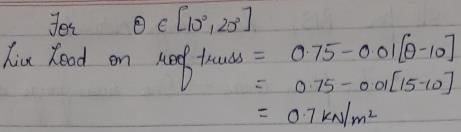
Raghav Mukherjee answered |
Snow load need not be considered when the roof is steeper than 10/12 pitch (40 degrees).
When vertical intermediate stiffeners are subjected to bending moments due to eccentricity of vertical loads, their moment of inertia (cm4) is increased by
Where,
M = the applied bending moment kN-m
D = overall depth of girder in mm
E = Young’s modulus in MPa
t = thickness of web, mm- a)125MD2/Et
- b)150MD2/Et
- c)175MD2/Et
- d)225MD2/Et
Correct answer is option 'B'. Can you explain this answer?
When vertical intermediate stiffeners are subjected to bending moments due to eccentricity of vertical loads, their moment of inertia (cm4) is increased by
Where,
M = the applied bending moment kN-m
D = overall depth of girder in mm
E = Young’s modulus in MPa
t = thickness of web, mm
Where,
M = the applied bending moment kN-m
D = overall depth of girder in mm
E = Young’s modulus in MPa
t = thickness of web, mm
a)
125MD2/Et
b)
150MD2/Et
c)
175MD2/Et
d)
225MD2/Et
|
|
Sravya Rane answered |
's modulus of the material in GPa
t = thickness of the stiffener in mm
y = distance from the neutral axis to the centroid of the stiffener in mm
The moment of inertia (I) of the stiffener can be calculated using the parallel axis theorem:
I_stiffener = I_stiffener' + A_stiffener * y^2
Where:
I_stiffener' = moment of inertia of the stiffener about its own centroid (cm^4)
A_stiffener = area of the stiffener (cm^2)
The moment of inertia of the stiffener about its own centroid can be calculated using the following formula:
I_stiffener' = (t * D^3) / 12
The area of the stiffener can be calculated by multiplying its thickness (t) by the depth of the girder (D), minus twice the distance from the neutral axis to the centroid of the stiffener (2y):
A_stiffener = t * (D - 2y)
Substituting the values of I_stiffener' and A_stiffener into the equation for I_stiffener:
I_stiffener = (t * D^3) / 12 + t * (D - 2y) * y^2
When the stiffener is subjected to bending moments due to eccentricity of vertical loads, the moment of inertia (I_stiffener) is increased.
The maximum permissible span of asbestos cement sheets is- a)650 mm
- b)810 mm
- c)1250 mm
- d)1680 mm
Correct answer is option 'D'. Can you explain this answer?
The maximum permissible span of asbestos cement sheets is
a)
650 mm
b)
810 mm
c)
1250 mm
d)
1680 mm
|
|
Arnab Saini answered |
Asbestos Cement Sheets
Asbestos cement sheets are commonly used as roofing and cladding material in industrial and agricultural buildings. These sheets are made by mixing asbestos fibers and cement together, which gives them strength, durability, and resistance to fire, weather, and insects.
Maximum Permissible Span
The maximum permissible span of asbestos cement sheets is the distance between two supports that the sheet can span without sagging or breaking. This span depends on various factors like the thickness and quality of the sheet, the load it will bear, the wind and snow load in the area, and the temperature and humidity conditions.
The maximum permissible span of asbestos cement sheets is calculated based on the deflection limit of L/180, where L is the span of the sheet. This means that the sheet should not deflect more than 1/180th of its length, which ensures that it remains stable and does not crack or break.
Answer
The maximum permissible span of asbestos cement sheets is 1680 mm or 1.68 meters. This means that any distance between two supports greater than 1.68 meters will cause the sheet to sag or break, which can be dangerous and expensive to repair. Therefore, it is important to choose the right thickness and quality of the sheet and install it properly with adequate supports and fasteners to ensure its safety and longevity.
Purlins are provided, in industrial buildings, over roof trusses to carry dead loads, live loads and wind loads. As per IS code, what are they assumed to be?- a)Simply supported
- b)Cantilever
- c)Continuous
- d)Fixed
Correct answer is option 'C'. Can you explain this answer?
Purlins are provided, in industrial buildings, over roof trusses to carry dead loads, live loads and wind loads. As per IS code, what are they assumed to be?
a)
Simply supported
b)
Cantilever
c)
Continuous
d)
Fixed
|
|
Aashna Chakraborty answered |
Purlins are assumed to be continuous beams.
A prismatic beam (shape factor, $) fixed at both ends carries UDL throughout the span. What is the ratio of collapse load to yield load?- a)

- b)

- c)

- d)

Correct answer is option 'A'. Can you explain this answer?
A prismatic beam (shape factor, $) fixed at both ends carries UDL throughout the span. What is the ratio of collapse load to yield load?
a)
b)
c)
d)
|
|
Srestha Datta answered |
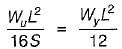
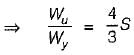
The collapse load for a prismatic beam fixed at both ends and caries UDL throughout the span is given by,
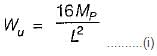
where Mp is its plastic moment.
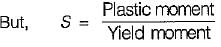
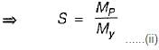
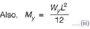
Substituting value of S from (ii) in (iii), we get,
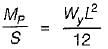
Substituting value of Mp from (i), we get,
The external wind pressure acting on a roof depends on- a)degree of permeability of roof
- b)slope of roof
- c)both (a) and (b)
- d)None of the above
Correct answer is option 'B'. Can you explain this answer?
The external wind pressure acting on a roof depends on
a)
degree of permeability of roof
b)
slope of roof
c)
both (a) and (b)
d)
None of the above
|
|
Pallabi Chavan answered |
External wind pressure on a roof
The external wind pressure acting on a roof is an important consideration in the design and construction of buildings. It is crucial to understand the factors that influence this pressure in order to ensure the stability and safety of the structure. Two significant factors that affect the external wind pressure on a roof are the degree of permeability of the roof and the slope of the roof.
Degree of permeability of the roof
The permeability of a roof refers to its ability to allow air to pass through it. Roofs can be classified as either permeable or impermeable based on their construction. Permeable roofs are designed to allow some air to pass through them, while impermeable roofs are designed to be airtight.
The degree of permeability of the roof affects the external wind pressure because it determines the airflow patterns around the roof. In the case of a permeable roof, some air can pass through it, which can reduce the pressure difference between the windward and leeward sides of the roof. This can result in a lower external wind pressure acting on the roof.
On the other hand, an impermeable roof does not allow air to pass through it, creating a higher pressure difference between the windward and leeward sides. This can lead to a higher external wind pressure on the roof.
Slope of the roof
The slope of the roof also influences the external wind pressure. A roof with a steep slope presents a larger surface area to the wind, which can result in higher wind forces acting on it. The increased wind forces can lead to higher external wind pressures on the roof.
Conversely, a roof with a shallow slope presents a smaller surface area to the wind, resulting in lower wind forces and external wind pressures.
Conclusion
In conclusion, the external wind pressure acting on a roof is influenced by both the degree of permeability of the roof and the slope of the roof. While the degree of permeability affects the airflow patterns around the roof, the slope of the roof determines the surface area exposed to the wind. Therefore, option (b) - the slope of the roof - is the correct answer to the question. Understanding these factors is crucial in designing and constructing roofs that can withstand external wind pressures and ensure the stability of the structure.
The internal pressure coefficient on walls for buildings with large permeability is taken as- a)±0,2
- b)±0.5
- c)±0.7
- d)0
Correct answer is option 'C'. Can you explain this answer?
The internal pressure coefficient on walls for buildings with large permeability is taken as
a)
±0,2
b)
±0.5
c)
±0.7
d)
0
|
|
Sreemoyee Joshi answered |
It includes both interna! as well as external pressure.
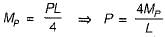
A load P is applied at the middle of a simply supported beam of span L. If the beam is made of ductile material, and Mp is the plastic moment, what is the ultimate value of P?- a)Mp/4L
- b)2Mp/L
- c)2.5Mp/L
- d)4 Mp/L
Correct answer is option 'D'. Can you explain this answer?
A load P is applied at the middle of a simply supported beam of span L. If the beam is made of ductile material, and Mp is the plastic moment, what is the ultimate value of P?
a)
Mp/4L
b)
2Mp/L
c)
2.5Mp/L
d)
4 Mp/L
|
|
Janhavi Datta answered |
The simply supported beam is a determinate one, hence one plastic hinge will be required for its complete collapse. This plastic hinge will be,
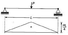
formed under the load. Hence the maximum bending moment can at the most reach to the plastic moment M
∴
formed under the load. Hence the maximum bending moment can at the most reach to the plastic moment M
p
.∴
An electric pole 5 m high is fixed into the foundation. It carries a wire at the top and is free to move sideways. The effective length of the pole is- a)3.25 m
- b)4,0m
- c)5.0 m
- d)10.0 m
Correct answer is option 'B'. Can you explain this answer?
An electric pole 5 m high is fixed into the foundation. It carries a wire at the top and is free to move sideways. The effective length of the pole is
a)
3.25 m
b)
4,0m
c)
5.0 m
d)
10.0 m
|
|
Milan Ghosh answered |
It is equivalent to a compression member whose one end is fixed against rotation and position and the other and neither restrained against rotation nor fixed in position in the direction perpendicular to wire. So effective length = 2L = 10 m.
In the direction of wire, the pole is hinged at wire end so effective length = 0.8L = 4.0 m.
In the direction of wire, the pole is hinged at wire end so effective length = 0.8L = 4.0 m.
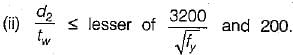
The intermediate transverse stiffener is needed in plate girder when (d/tw) of web is
where d = depth of web;
tw = thickness of web plate- a)>85
- b)<85
- c)>120
- d)= 60
Correct answer is option 'A'. Can you explain this answer?
The intermediate transverse stiffener is needed in plate girder when (d/tw) of web is
where d = depth of web;
tw = thickness of web plate
where d = depth of web;
tw = thickness of web plate
a)
>85
b)
<85
c)
>120
d)
= 60
|
|
Bhargavi Sengupta answered |
IS : 800-1984 recommends the provision of web stiffeners as follows:
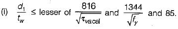
No stiffener is required
No stiffener is required
Vertical stiffeners are provided.
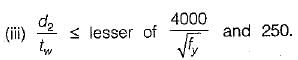
Vertical stiffeners and one horizontal stiffener at a distance from the compression flange equal to two-fifths of the distance from the compression flange to the neutral axis are provided.
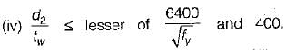
The requirement is the same as in (iii) plus a horizontal stiffener at the neutral axis, where d2 = 2 x clear distance from compression flange angles or plate or tongue plate to the neutral axis.
A 6 mm thick mild steel plate is connected to an 8 mm thick plate by 16 mm diameter shop rivets. What is-the number of rivets required to carry an 80 kN load?- a)2
- b)3
- c)4
- d)6
Correct answer is option 'C'. Can you explain this answer?
A 6 mm thick mild steel plate is connected to an 8 mm thick plate by 16 mm diameter shop rivets. What is-the number of rivets required to carry an 80 kN load?
a)
2
b)
3
c)
4
d)
6
|
|
Poulomi Khanna answered |
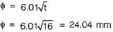
For shop rivets permissible stresses are, In shearing, τs = 100 MPa
In bearing, σb = 300 MPa
The gross diameter of hole (D)
.= 16 + 1.5 = 17.5 mm
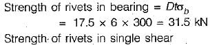
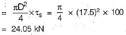
∴ Rivet value = 24.05 kN
Hence, number of rivets required
In bearing, σb = 300 MPa
The gross diameter of hole (D)
.= 16 + 1.5 = 17.5 mm
∴ Rivet value = 24.05 kN
Hence, number of rivets required
The type of stress induced in the foundation bolts fixing a column to its footing is- a)pure compression
- b)bearing
- c)pure tension
- d)bending
Correct answer is option 'C'. Can you explain this answer?
The type of stress induced in the foundation bolts fixing a column to its footing is
a)
pure compression
b)
bearing
c)
pure tension
d)
bending
|
|
Harsh Khanna answered |
The axial force from column needs to be transferred from column to footing and thus, mainly type of stress induced in the foundation bolts is pure tension.
If the thickness of thinnest outside plate is 10 mm, then the maximum pitch of rivets in tension will be taken as- a)120 mm
- b)160 mm
- c)200 mm
- d)300 mm
Correct answer is option 'B'. Can you explain this answer?
If the thickness of thinnest outside plate is 10 mm, then the maximum pitch of rivets in tension will be taken as
a)
120 mm
b)
160 mm
c)
200 mm
d)
300 mm
|
|
Diya Sarkar answered |
Maximum Pitch of Rivets in Tension
- The pitch of rivets is the distance between the centers of two adjacent rivets.
- In tension members, the pitch of rivets is limited to prevent the development of stress concentrations that may lead to failure.
- The maximum pitch of rivets in tension is given by the formula:
Max pitch = 16t, where t is the thickness of the thinnest outside plate.
- Therefore, if the thickness of the thinnest outside plate is 10 mm, the maximum pitch of rivets in tension will be:
Max pitch = 16 x 10 = 160 mm.
- Hence, the correct answer is option B, which is 160 mm.
Minimum spacing of vertical stiffeners is limited to
where d is the distance between flange angles.- a)D/4
- b)D/3
- c)D/2
- d)2D/3
Correct answer is option 'B'. Can you explain this answer?
Minimum spacing of vertical stiffeners is limited to
where d is the distance between flange angles.
where d is the distance between flange angles.
a)
D/4
b)
D/3
c)
D/2
d)
2D/3
|
|
Anmol Roy answered |
Vertical stiffeners are provided at the spacing of 0.33 of to 1.5 d where d is the distance between the flanges ignoring fillets and if horizontal stiffeners are also provided d is the maximum clear depth of the web. Spacing can be reduced near the supports where the shear force is large compared to the centre of the girder.
Chapter doubts & questions for Design of Steel Structures - GATE Civil Engineering (CE) 2026 Mock Test Series 2025 is part of Civil Engineering (CE) exam preparation. The chapters have been prepared according to the Civil Engineering (CE) exam syllabus. The Chapter doubts & questions, notes, tests & MCQs are made for Civil Engineering (CE) 2025 Exam. Find important definitions, questions, notes, meanings, examples, exercises, MCQs and online tests here.
Chapter doubts & questions of Design of Steel Structures - GATE Civil Engineering (CE) 2026 Mock Test Series in English & Hindi are available as part of Civil Engineering (CE) exam.
Download more important topics, notes, lectures and mock test series for Civil Engineering (CE) Exam by signing up for free.
GATE Civil Engineering (CE) 2026 Mock Test Series
33 docs|280 tests
|

Signup to see your scores go up within 7 days!
Study with 1000+ FREE Docs, Videos & Tests
10M+ students study on EduRev
|
© EduRev
|
Education Revolution
|


|


Signup to see your scores
go up
within 7 days!
within 7 days!
Takes less than 10 seconds to signup