


All Exams >
Electrical Engineering (EE) >
Analog and Digital Electronics >
All Questions
All questions of Data Selectors and Multiplexers for Electrical Engineering (EE) Exam
It is possible for an enable or strobe input to undergo an expansion of two or more MUX ICs to the digital multiplexer with the proficiency of large number of _______- a)Inputs
- b)Outputs
- c)Selection lines
- d)Enable lines
Correct answer is option 'A'. Can you explain this answer?
It is possible for an enable or strobe input to undergo an expansion of two or more MUX ICs to the digital multiplexer with the proficiency of large number of _______
a)
Inputs
b)
Outputs
c)
Selection lines
d)
Enable lines
|
|
Ashutosh Majumdar answered |
Answer:
To understand the answer to this question, let's first discuss the basic concept of a digital multiplexer.
A digital multiplexer, also known as a data selector, is a combinational circuit that selects one of many input signals and routes it to a single output line based on the control inputs. It is widely used in various electronic applications, such as data transmission, signal routing, and digital communication systems.
A multiplexer can have multiple inputs, outputs, and selection lines. The selection lines determine which input signal gets routed to the output line. The number of selection lines in a multiplexer is determined by the number of input lines and is given by the equation:
n = log2(N)
Where n is the number of selection lines and N is the number of input lines. For example, if we have 4 input lines, we would need 2 selection lines (n = log2(4) = 2).
In the given question, it is mentioned that an enable or strobe input undergoes an expansion of two or more multiplexer ICs. This means that multiple multiplexer ICs are cascaded together to form a larger multiplexer.
When multiple multiplexer ICs are cascaded, the enable or strobe input of each IC is connected in parallel. This allows the enable or strobe input to control the operation of all the cascaded ICs simultaneously.
By expanding the multiplexer using multiple ICs, we can increase the number of inputs that can be selected. Each IC will have a certain number of inputs, outputs, and selection lines. By cascading multiple ICs together, we can effectively increase the number of inputs of the multiplexer.
However, it is important to note that the number of outputs and selection lines remains the same, as these are determined by the individual ICs. Only the number of inputs can be increased by cascading multiple ICs.
Therefore, the correct answer to the given question is option 'A' - Inputs.

Which is the major functioning responsibility of the multiplexing combinational circuit?- a)Decoding the binary information
- b)Generation of all minterms in an output function with OR-gate
- c)Generation of selected path between multiple sources and a single destination
- d)Encoding of binary information
Correct answer is option 'C'. Can you explain this answer?
Which is the major functioning responsibility of the multiplexing combinational circuit?
a)
Decoding the binary information
b)
Generation of all minterms in an output function with OR-gate
c)
Generation of selected path between multiple sources and a single destination
d)
Encoding of binary information

|
Isha Bajaj answered |
The major functioning responsibility of a multiplexing combinational circuit is the generation of a selected path between multiple sources and a single destination. Let's break down this answer in detail:
1. What is a multiplexing combinational circuit?
A multiplexing combinational circuit is a digital circuit that allows multiple input signals to be transmitted over a single transmission line or channel. It uses a combination of logic gates to select and route the desired input signal to the output.
2. Understanding the options:
a) Decoding the binary information:
Decoding refers to the process of converting a binary code into a more meaningful form. While decoding can be a part of the multiplexing process, it is not the major functioning responsibility of the circuit.
b) Generation of all minterms in an output function with OR-gate:
A minterm is a product term in Boolean algebra that represents a specific combination of input variables. While generating minterms can be a part of the multiplexing process, it is not the major functioning responsibility of the circuit.
c) Generation of selected path between multiple sources and a single destination:
This is the correct answer. The main purpose of a multiplexing combinational circuit is to select and route the desired input signal to a single output destination. It allows multiple sources to share a common transmission line or channel, enabling efficient communication.
d) Encoding of binary information:
Encoding refers to the process of converting meaningful data into a coded form. While encoding can be a part of the multiplexing process, it is not the major functioning responsibility of the circuit.
3. Importance of selecting a path:
In many applications, especially in communication systems, there is a need to transmit multiple signals over limited resources. Multiplexing allows efficient utilization of these resources by selecting and routing the desired signals to their respective destinations. By choosing the appropriate path, the multiplexing combinational circuit ensures that the desired signal reaches the destination without interference or loss.
4. How the circuit works:
The multiplexing combinational circuit uses logic gates, such as AND gates and OR gates, to select the desired input signal based on control signals. These control signals determine which input signal is routed to the output. By manipulating the control signals, different input signals can be selected and transmitted at different times, effectively sharing the transmission line or channel.
In conclusion, the major functioning responsibility of a multiplexing combinational circuit is to generate a selected path between multiple sources and a single destination. It allows efficient utilization of resources and enables the transmission of multiple signals over a common transmission line or channel.
The output Q4 of this 1-to-8 demultiplexer is ____________
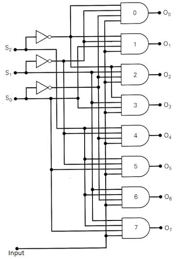
- a)Q2.(Q1)’.Q0.I
- b)Q2.Q1.(Q0)’.I
- c)Q2.(Q1)’.(Q0)’.I
- d)Q2.(Q1).Q0.I
Correct answer is option 'C'. Can you explain this answer?
The output Q4 of this 1-to-8 demultiplexer is ____________
a)
Q2.(Q1)’.Q0.I
b)
Q2.Q1.(Q0)’.I
c)
Q2.(Q1)’.(Q0)’.I
d)
Q2.(Q1).Q0.I
|
|
Pooja Patel answered |
The output Y4 = Q2.(Q1)’.(Q0)’.I. since the bit combinations of 4 are 100.
What is the function of an enable input on a multiplexer chip?- a)To apply Vcc
- b)To connect ground
- c)To active the entire chip
- d)To active one half of the chip
Correct answer is option 'C'. Can you explain this answer?
What is the function of an enable input on a multiplexer chip?
a)
To apply Vcc
b)
To connect ground
c)
To active the entire chip
d)
To active one half of the chip
|
|
Siddharth Khanna answered |
The function of an enable input on a multiplexer chip is to activate or deactivate the entire chip. When the enable input is high (or active), the multiplexer chip is enabled and can perform its intended function. On the other hand, when the enable input is low (or inactive), the multiplexer chip is disabled and its outputs are in a high-impedance state.
When the enable input is active, the multiplexer chip acts as a data selector, allowing one of multiple inputs to be selected and routed to the output. The selection of the input is determined by the control inputs of the chip.
Below is a detailed explanation of the function of the enable input on a multiplexer chip:
1. Multiplexer Basics:
- A multiplexer, also known as a data selector, is a digital circuit that selects one of many inputs and routes it to a single output.
- It is commonly represented by the symbol ⊕ or MUX.
2. Enable Input:
- The enable input on a multiplexer chip is denoted as EN or E, and it controls the activation of the chip.
- The enable input is typically an active-high input, meaning that when it is high (logic 1), the chip is enabled.
3. Chip Activation:
- When the enable input is active (high), the multiplexer chip is enabled and can perform its function.
- The chip becomes operational, and its outputs are determined by the control inputs and the selected input.
- The selected input is determined by the control inputs, such as address lines or select inputs.
4. Chip Deactivation:
- When the enable input is inactive (low), the multiplexer chip is disabled.
- The chip enters a high-impedance state, which means that its outputs are effectively disconnected and do not drive any signal.
- This high-impedance state prevents any interference or conflicts with other circuitry that may be connected to the outputs of the disabled chip.
5. Usefulness of Enable Input:
- The enable input is useful in applications where the activation or deactivation of the multiplexer chip needs to be controlled.
- It allows for greater flexibility in circuit design by providing the ability to enable or disable the chip as needed.
In summary, the enable input on a multiplexer chip is responsible for activating or deactivating the entire chip. When the enable input is high, the chip is enabled and can perform its function of selecting and routing one of multiple inputs to the output. When the enable input is low, the chip is disabled, and its outputs are in a high-impedance state.
Which IC is used for the implementation of 1-to-16 DEMUX?- a)IC 74154
- b)IC 74155
- c)IC 74139
- d)IC 74138
Correct answer is option 'A'. Can you explain this answer?
Which IC is used for the implementation of 1-to-16 DEMUX?
a)
IC 74154
b)
IC 74155
c)
IC 74139
d)
IC 74138
|
|
Mihir Chawla answered |
IC 74154 is used for the implementation of 1-to-16 DEMUX.
Explanation:
1-to-16 DEMUX is a digital circuit which takes one input and distributes it across the 16 output lines based on the input binary address. It is used in various applications such as memory addressing, data routing, and selection of input/output lines.
IC 74154 is a 4-to-16 decoder/demultiplexer IC with active-low outputs. It has 4 select inputs (A, B, C, D) and 16 output lines. Each output line corresponds to a unique combination of the select inputs. When a particular combination of select inputs is enabled, the corresponding output line goes low while all other output lines remain high.
To implement a 1-to-16 DEMUX using IC 74154, we can connect the input to one of the select inputs (e.g. A) and tie the remaining select inputs (B, C, D) to ground. This enables the output line corresponding to the input address (A=1) while keeping all other output lines high.
Therefore, IC 74154 is the correct choice for implementing a 1-to-16 DEMUX due to its multiple output lines and select inputs, making it suitable for addressing and routing applications.
Which of the following circuits can be used as a series to parallel converter?- a)Encoder
- b)Decoder
- c)De-multiplexer
- d)Multiplexer
Correct answer is option 'C'. Can you explain this answer?
Which of the following circuits can be used as a series to parallel converter?
a)
Encoder
b)
Decoder
c)
De-multiplexer
d)
Multiplexer
|
|
Sanskriti Desai answered |
Series to Parallel Converter:
A series to parallel converter is a circuit that takes a series input and converts it into a parallel output. This type of converter is commonly used in various applications where the input needs to be distributed to multiple outputs.
Options:
a) Encoder: An encoder is a circuit that converts multiple inputs into a coded output. It is used in applications such as data compression, error detection, and data transmission. It does not perform the function of converting a series input into a parallel output, so it cannot be used as a series to parallel converter.
b) Decoder: A decoder is a circuit that performs the reverse operation of an encoder. It takes a coded input and converts it into multiple outputs. Like an encoder, it does not convert a series input into a parallel output, so it cannot be used as a series to parallel converter.
c) De-multiplexer: A de-multiplexer, also known as a demux, is a circuit that takes a single input and directs it to one of several outputs based on control signals. It has multiple outputs, making it suitable for converting a series input into a parallel output. Therefore, a de-multiplexer can be used as a series to parallel converter.
d) Multiplexer: A multiplexer, also known as a mux, is a circuit that combines multiple inputs into a single output based on control signals. It does not convert a series input into a parallel output, so it cannot be used as a series to parallel converter.
Conclusion:
The correct option is c) De-multiplexer, as it can be used as a series to parallel converter by directing a series input to multiple parallel outputs based on control signals.
In 1-to-4 multiplexer, if C1 = 0 & C2 = 1, then the output will be ___________- a)Y0
- b)Y1
- c)Y2
- d)Y3
Correct answer is option 'B'. Can you explain this answer?
In 1-to-4 multiplexer, if C1 = 0 & C2 = 1, then the output will be ___________
a)
Y0
b)
Y1
c)
Y2
d)
Y3
|
|
Swati Tiwari answered |
If C1 = 0 in a 1-to-4 multiplexer, it means that the control input C1 is set to logic 0.
In a 1-to-4 multiplexer, there are two control inputs, C1 and C0, which select one of the four input lines to be connected to the output line. The control inputs are usually binary, meaning they can have a value of 0 or 1.
When C1 = 0, it specifies that the 0th input line is selected. This means that the output of the multiplexer will be the same as the signal on the 0th input line. The other input lines (1st, 2nd, and 3rd) are not connected to the output in this case.
Which combinational circuit is renowned for selecting a single input from multiple inputs & directing the binary information to output line?- a)Data Selector
- b)Data distributor
- c)Both data selector and data distributor
- d)DeMultiplexer
Correct answer is option 'A'. Can you explain this answer?
Which combinational circuit is renowned for selecting a single input from multiple inputs & directing the binary information to output line?
a)
Data Selector
b)
Data distributor
c)
Both data selector and data distributor
d)
DeMultiplexer
|
|
Arpita Banerjee answered |
The multiplexer (MUX) circuit is renowned for selecting a single input from multiple inputs.
In a multiplexer the output depends on its ___________- a)Data inputs
- b)Select inputs
- c)Select outputs
- d)Enable pin
Correct answer is option 'B'. Can you explain this answer?
In a multiplexer the output depends on its ___________
a)
Data inputs
b)
Select inputs
c)
Select outputs
d)
Enable pin
|
|
Sanaya Basu answered |
Multiplexer
A multiplexer, also known as a data selector, is a combinational circuit that selects one of many input signals and forwards it to a single output line. It is commonly used in digital systems to route data from multiple sources to a single destination.
Function of a Multiplexer
The function of a multiplexer is to select one of the input lines and connect it to the output line based on the select inputs. The number of select inputs determines the number of input lines a multiplexer can have. For example, a 2-input multiplexer has one select input and two data inputs, while a 4-input multiplexer has two select inputs and four data inputs.
Output Dependency
The output of a multiplexer depends on its select inputs. The select inputs determine which data input is connected to the output. When the select inputs change, the output of the multiplexer may also change.
Select Inputs
The select inputs of a multiplexer are used to control which data input is selected. The select inputs are binary inputs, meaning they can have two possible values: 0 and 1. The number of select inputs determines the number of data inputs that can be selected.
Example
Let's consider a 2-input multiplexer with inputs A and B, and a select input S. The output of the multiplexer is denoted as Y.
- When S = 0, the data input A is selected and connected to the output Y.
- When S = 1, the data input B is selected and connected to the output Y.
So, the output of the multiplexer depends on the select input S. If S = 0, the output is based on input A, and if S = 1, the output is based on input B.
Conclusion
In conclusion, the output of a multiplexer depends on its select inputs. The select inputs control which data input is selected and connected to the output. The select inputs are binary inputs, and their values determine the output of the multiplexer. Thus, the correct answer is option B - select inputs.
One multiplexer can take the place of ___________- a)Several SSI logic gates
- b)Combinational logic circuits
- c)Several Ex-NOR gates
- d)Several SSI logic gates or combinational logic circuits
Correct answer is option 'D'. Can you explain this answer?
One multiplexer can take the place of ___________
a)
Several SSI logic gates
b)
Combinational logic circuits
c)
Several Ex-NOR gates
d)
Several SSI logic gates or combinational logic circuits
|
|
Pooja Patel answered |
A multiplexer (or MUX) is a device that selects one of several analog or digital input signals and forwards the selected input into a single line, depending on the active select lines. Since many operational behaviour can be performed by using a multiplexer. Whereas, a combinational circuit is a combination of many logic gates which makes the circuit more complex.
What is a multiplexer?- a)It is a type of decoder which decodes several inputs and gives one output
- b)A multiplexer is a device which converts many signals into one
- c)It takes one input and results into many output
- d)It is a type of encoder which decodes several inputs and gives one output
Correct answer is option 'B'. Can you explain this answer?
What is a multiplexer?
a)
It is a type of decoder which decodes several inputs and gives one output
b)
A multiplexer is a device which converts many signals into one
c)
It takes one input and results into many output
d)
It is a type of encoder which decodes several inputs and gives one output
|
|
Prerna Tiwari answered |
Explanation:
A multiplexer is a device that combines multiple signals into one output signal. It is also known as a data selector, as it selects one of several input signals and forwards the selected signal to the output. The number of input signals can be two or more, and the selection of the input signal can be done through a control signal.
Working Principle:
The working principle of a multiplexer is based on the Boolean expression. A multiplexer has n input lines and one output line. The control signal selects which input to send to the output. The control signal is converted into a binary number, which is used to select one of the input lines.
Types of Multiplexers:
There are different types of multiplexers, including:
1. 2:1 Multiplexer: It has two input lines and one output line.
2. 4:1 Multiplexer: It has four input lines and one output line.
3. 8:1 Multiplexer: It has eight input lines and one output line.
Applications:
Multiplexers are used in various applications, including:
1. Communication systems: Multiplexers are used in communication systems to combine multiple signals into a single output signal.
2. Computer memory: Multiplexers are used in computer memory to select a particular memory cell.
3. Data transmission: Multiplexers are used in data transmission systems to select a particular data stream.
4. Digital circuit design: Multiplexers are used in digital circuit design to select an input signal based on a control signal.
Conclusion:
In conclusion, a multiplexer is a device that combines multiple signals into one output signal. It is widely used in various applications, including communication systems, computer memory, data transmission, and digital circuit design.
How many AND gates are required for a 1-to-8 multiplexer?- a)2
- b)6
- c)8
- d)5
Correct answer is option 'C'. Can you explain this answer?
How many AND gates are required for a 1-to-8 multiplexer?
a)
2
b)
6
c)
8
d)
5
|
|
Pooja Patel answered |
The number of AND gates required will be equal to the number of outputs in a demultiplexer, which are 8.
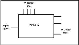
Most demultiplexers facilitate which type of conversion?- a)Decimal-to-hexadecimal
- b)Single input, multiple outputs
- c)AC to DC
- d)Odd parity to even parity
Correct answer is option 'B'. Can you explain this answer?
Most demultiplexers facilitate which type of conversion?
a)
Decimal-to-hexadecimal
b)
Single input, multiple outputs
c)
AC to DC
d)
Odd parity to even parity
|
|
Pooja Patel answered |
A demultiplexer sends a single input to multiple outputs, depending on the select lines. Demultiplexer converts single input into multiple outputs.
Why is a demultiplexer called a data distributor?- a)The input will be distributed to one of the outputs
- b)One of the inputs will be selected for the output
- c)The output will be distributed to one of the inputs
- d)Single input to Single Output
Correct answer is option 'A'. Can you explain this answer?
Why is a demultiplexer called a data distributor?
a)
The input will be distributed to one of the outputs
b)
One of the inputs will be selected for the output
c)
The output will be distributed to one of the inputs
d)
Single input to Single Output
|
|
Pooja Patel answered |
A demultiplexer sends a single input to multiple outputs, depending on the select lines. For one input, the demultiplexer gives several outputs. That is why it is called a data distributor.
The enable input is also known as ___________- a)Select input
- b)Decoded input
- c)Strobe
- d)Sink
Correct answer is option 'C'. Can you explain this answer?
The enable input is also known as ___________
a)
Select input
b)
Decoded input
c)
Strobe
d)
Sink
|
|
Pooja Patel answered |
The enable input is also known as strobe which is used to cascade two or more multiplexer ICs to construct a multiplexer with a larger number of inputs. Enable input activates the multiplexer to operate.
The word demultiplex means ___________- a)One into many
- b)Many into one
- c)Distributor
- d)One into many as well as Distributor
Correct answer is option 'D'. Can you explain this answer?
The word demultiplex means ___________
a)
One into many
b)
Many into one
c)
Distributor
d)
One into many as well as Distributor
|
|
Pooja Patel answered |
The word demultiplex means “one into many” and distributor. A demultiplexer sends a single input to multiple outputs, depending on the select lines. It is clear from the diagram:
In 1-to-4 demultiplexer, how many select lines are required?- a)2
- b)3
- c)4
- d)5
Correct answer is option 'A'. Can you explain this answer?
In 1-to-4 demultiplexer, how many select lines are required?
a)
2
b)
3
c)
4
d)
5
|
|
Pooja Patel answered |
The formula for total no. of outputs is given by 2n, where n is the no. of select lines. Therefore, for 1:4 demultiplexer, 2 select lines are required.
A digital multiplexer is a combinational circuit that selects ___________- a)One digital information from several sources and transmits the selected one
- b)Many digital information and convert them into one
- c)Many decimal inputs and transmits the selected information
- d)Many decimal outputs and accepts the selected information
Correct answer is option 'A'. Can you explain this answer?
A digital multiplexer is a combinational circuit that selects ___________
a)
One digital information from several sources and transmits the selected one
b)
Many digital information and convert them into one
c)
Many decimal inputs and transmits the selected information
d)
Many decimal outputs and accepts the selected information
|
|
Palak Verma answered |
Introduction:
A digital multiplexer is a combinational circuit that is used to select one digital information from multiple sources and transmit the selected one. It is commonly known as a data selector or data multiplexer. The selection of the input data is based on the control signals provided to the circuit.
Explanation:
A digital multiplexer has multiple input lines, one output line, and several control signals. The number of input lines in a multiplexer depends on the number of sources from which the digital information is received. The control signals determine which input line is selected and transmitted to the output line.
Working:
The operation of a digital multiplexer can be understood with the help of its truth table. Let's consider a 4:1 multiplexer with 4 input lines (D0, D1, D2, D3), 1 output line (Y), and 2 control signals (S0, S1).
- The control signals (S0, S1) determine which input line is selected and transmitted to the output line.
- For example, if (S0, S1) = (0, 0), the input line D0 is selected and transmitted to the output line.
- Similarly, for (S0, S1) = (0, 1), D1 is selected; for (S0, S1) = (1, 0), D2 is selected; and for (S0, S1) = (1, 1), D3 is selected.
- The selected input is then transmitted to the output line Y.
Benefits:
A digital multiplexer offers several benefits in digital circuit design:
- It reduces the complexity of circuitry by enabling the selection of one digital information from multiple sources using a single circuit.
- It saves space on integrated circuits by eliminating the need for separate circuits for each input source.
- It reduces the number of interconnections required in a circuit, leading to improved reliability and reduced power consumption.
Conclusion:
In conclusion, a digital multiplexer is a combinational circuit that selects one digital information from several sources and transmits the selected one. It is an essential component in digital circuit design, providing flexibility, simplicity, and efficiency in data selection and transmission.
Which of the following statements about the demultiplexers is INCORRECT ?- a)1-line to 8-line demultiplexer consist of eight AND gates, all of them connected to a single line data input.
- b)It takes single input and distributes it over several outputs.
- c)It is used as anti-clock demultiplexers in synchronous data transmission systems in the receivers and security monitoring systems etc.
- d)It takes one input data source and selectively distributes it to 1-of-N output channels just like a multi-position switch.
Correct answer is option 'C'. Can you explain this answer?
Which of the following statements about the demultiplexers is INCORRECT ?
a)
1-line to 8-line demultiplexer consist of eight AND gates, all of them connected to a single line data input.
b)
It takes single input and distributes it over several outputs.
c)
It is used as anti-clock demultiplexers in synchronous data transmission systems in the receivers and security monitoring systems etc.
d)
It takes one input data source and selectively distributes it to 1-of-N output channels just like a multi-position switch.
|
|
Kajal Yadav answered |
Demultiplexers:
A demultiplexer, also known as a demux, is a combinational logic circuit that takes a single input and distributes it over several outputs based on the control signals. It is the opposite of a multiplexer, which takes multiple inputs and selects one output based on the control signals. Demultiplexers are commonly used in data transmission systems, security monitoring systems, and other applications.
Statement Analysis:
Let's analyze each statement to determine which one is incorrect.
Statement a:
1-line to 8-line demultiplexer consists of eight AND gates, all of them connected to a single-line data input.
This statement is correct. In a 1-line to 8-line demultiplexer, there are eight output lines and one input line. Each output line is connected to an AND gate with the input line. The control signals determine which output line will receive the input.
Statement b:
A demultiplexer takes a single input and distributes it over several outputs.
This statement is correct. The purpose of a demultiplexer is to take a single input and distribute it to multiple outputs based on the control signals. It acts as a reverse of a multiplexer.
Statement c:
A demultiplexer is used as anti-clock demultiplexers in synchronous data transmission systems in receivers and security monitoring systems, etc.
This statement is incorrect. There is no such thing as an "anti-clock demultiplexer." This term is not commonly used in the context of demultiplexers. The use of demultiplexers in synchronous data transmission systems and security monitoring systems is correct, but the term "anti-clock" is not appropriate.
Statement d:
A demultiplexer takes one input data source and selectively distributes it to 1-of-N output channels, just like a multi-position switch.
This statement is correct. A demultiplexer functions similarly to a multi-position switch. It takes a single input and selectively distributes it to one of the N output channels based on the control signals.
Conclusion:
Based on the analysis, the incorrect statement is option 'C'. There is no such thing as an "anti-clock demultiplexer," and the term is not commonly used in the context of demultiplexers.
A basic multiplexer principle can be demonstrated through the use of a ________- a)Single-pole relay
- b)DPDT switch
- c)Rotary switch
- d)Linear stepper
Correct answer is option 'C'. Can you explain this answer?
A basic multiplexer principle can be demonstrated through the use of a ________
a)
Single-pole relay
b)
DPDT switch
c)
Rotary switch
d)
Linear stepper
|
|
Vaishnavi Nair answered |
Understanding Multiplexers
A multiplexer (MUX) is an electronic device that selects one of many input signals and forwards the selected input to a single output line. The basic principle behind multiplexers can be demonstrated effectively using a rotary switch.
Why a Rotary Switch?
- Multiple Inputs: A rotary switch allows for multiple positions, each corresponding to a different input. This mimics the MUX's ability to handle various input signals.
- Selection Mechanism: By rotating the switch, users can select which input is connected to the output. This is analogous to how a multiplexer uses control signals to determine which input to forward.
- Simplicity: Rotary switches are straightforward in design and operation, making them ideal for educational demonstrations of the MUX concept.
Comparative Analysis with Other Options
- Single-pole Relay: While relays can switch circuits, they typically handle only one input at a time and lack the multi-input functionality of a MUX.
- DPDT Switch: Although a DPDT (Double Pole Double Throw) switch can route signals, it does not provide the same level of multi-input selection as a rotary switch.
- Linear Stepper: Stepper motors are used for precise control of rotation and position but do not serve the purpose of switching multiple inputs to a single output.
Conclusion
In summary, a rotary switch effectively demonstrates the principle of a multiplexer due to its ability to select from multiple inputs and direct a single output. This makes it the most suitable choice among the given options for illustrating MUX functionality.
The IC 74LS138 is a ____.- a)8 bit adder
- b)8 line demultiplexer
- c)8 bit subtractor
- d)8 line multiplexer
Correct answer is option 'B'. Can you explain this answer?
The IC 74LS138 is a ____.
a)
8 bit adder
b)
8 line demultiplexer
c)
8 bit subtractor
d)
8 line multiplexer
|
|
Dipika Basak answered |
The IC 74LS138 is an 8-line demultiplexer. Let's break down the answer and understand why option 'B' is the correct answer.
1. What is a demultiplexer?
- A demultiplexer, also known as a demux, is a combinational logic circuit that takes a single input and distributes it to one of several possible outputs based on the control signals.
2. Understanding the IC 74LS138:
- The IC 74LS138 is a specific type of demultiplexer that is commonly used in digital circuits.
- It has 3 input pins, A, B, and C, which are used to select the output line.
- The demultiplexer has 8 output pins, Y0 to Y7, which correspond to 8 possible outputs.
- The demultiplexer also has an active low enable input, called E1, which is used to enable or disable the demultiplexer operation.
3. Function of the IC 74LS138:
- The demultiplexer takes in a 3-bit binary input (A, B, and C) and uses these inputs to select one of the 8 output lines.
- The selected output line is then activated, while all other output lines remain inactive.
- The demultiplexer operates based on the combination of the input signals and the enable input.
- When the enable input (E1) is low (0), the demultiplexer is enabled and the selected output line is activated.
- When the enable input is high (1), the demultiplexer is disabled and none of the output lines are activated.
4. Applications of the IC 74LS138:
- The demultiplexer is widely used in digital circuits for various applications such as data routing, address decoding, memory interfacing, and signal distribution.
- It is commonly used in microprocessors and microcontrollers to decode address lines and select specific memory or peripheral devices.
- It can be used to implement complex logic functions by combining multiple demultiplexers.
In conclusion, the IC 74LS138 is an 8-line demultiplexer that takes a 3-bit binary input and selects one of the 8 output lines based on the input signals and the enable input. It is widely used in digital circuits for various applications including address decoding and data routing.
How many select lines are required for a 1-to-8 demultiplexer?- a)2
- b)3
- c)4
- d)5
Correct answer is option 'B'. Can you explain this answer?
How many select lines are required for a 1-to-8 demultiplexer?
a)
2
b)
3
c)
4
d)
5
|
|
Pooja Patel answered |
The formula for total no. of outputs is given by 2n, where n is the no. of select lines. In this case n = 3 since 23 = 8.
Name the following figure.
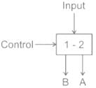
- a)Multiplexer
- b)De-multiplexer
- c)Combinational circuit
- d)Encoder
Correct answer is option 'B'. Can you explain this answer?
Name the following figure.
a)
Multiplexer
b)
De-multiplexer
c)
Combinational circuit
d)
Encoder
|
|
Pooja Patel answered |
Multiplexer: Multiplexer is a device that has multiple inputs and single line output.
De-multiplexer: De-multiplexer is a device that has a signal inputs line and multiple line outputs.
The given figure has one input and two outputs. Hence it is De-multiplexer.
De-multiplexer: De-multiplexer is a device that has a signal inputs line and multiple line outputs.
The given figure has one input and two outputs. Hence it is De-multiplexer.
Combinational circuit:
- Combinational and sequential circuits are the digital circuits made using logic gates
- Present output depends on the present input only
- No feedback is present
- No memory is present
Encoder: Encoder is used to converter other codes to binary
In a 1 to 4 De-multiplexer, how many select input lines are required?- a)2
- b)3
- c)4
- d)5
Correct answer is option 'A'. Can you explain this answer?
In a 1 to 4 De-multiplexer, how many select input lines are required?
a)
2
b)
3
c)
4
d)
5
|
|
Pooja Patel answered |
DEMUX:
A demultiplexer (or demux) is a device that takes a single input line and routes it to one of several digital output lines.
It consists of 2n outputs and has n selection lines, which are used to select which output line to send the input. It is also called as a data distributor.
A demultiplexer (or demux) is a device that takes a single input line and routes it to one of several digital output lines.
It consists of 2n outputs and has n selection lines, which are used to select which output line to send the input. It is also called as a data distributor.
If the number of n selected input lines is equal to 2m then it requires _____ select lines.- a)2
- b)m
- c)n
- d)2n
Correct answer is option 'B'. Can you explain this answer?
If the number of n selected input lines is equal to 2m then it requires _____ select lines.
a)
2
b)
m
c)
n
d)
2n
|
|
Pooja Patel answered |
If the number of n selected input lines is equal to 2m then it requires m select lines to select one of m select lines.
Chapter doubts & questions for Data Selectors and Multiplexers - Analog and Digital Electronics 2025 is part of Electrical Engineering (EE) exam preparation. The chapters have been prepared according to the Electrical Engineering (EE) exam syllabus. The Chapter doubts & questions, notes, tests & MCQs are made for Electrical Engineering (EE) 2025 Exam. Find important definitions, questions, notes, meanings, examples, exercises, MCQs and online tests here.
Chapter doubts & questions of Data Selectors and Multiplexers - Analog and Digital Electronics in English & Hindi are available as part of Electrical Engineering (EE) exam.
Download more important topics, notes, lectures and mock test series for Electrical Engineering (EE) Exam by signing up for free.
Analog and Digital Electronics
135 videos|167 docs|71 tests
|
|
© EduRev
|
Education Revolution
|


|


Signup to see your scores
go up
within 7 days!
within 7 days!
Takes less than 10 seconds to signup