


All Exams >
Mechanical Engineering >
Design of Machine Elements >
All Questions
All questions of Riveted, Bolted & Welded Joints for Mechanical Engineering Exam
Themit consists of a finely divided mixture of iron oxide and copper.- a)True
- b)False
Correct answer is option 'B'. Can you explain this answer?
Themit consists of a finely divided mixture of iron oxide and copper.
a)
True
b)
False
|
|
Sagnik Choudhary answered |
Explanation: Thermite is a mixture of iron oxide and copper.

All welding processes require pressure along with heat.- a)All welding processes require pressure along with heat.
- b)All welding processes require pressure along with heat.a) Yesb ) No, fusion doesn’t require
- c)Can’t be stated
- d)None of the listed
Correct answer is option 'B'. Can you explain this answer?
All welding processes require pressure along with heat.
a)
All welding processes require pressure along with heat.
b)
All welding processes require pressure along with heat.a) Yesb ) No, fusion doesn’t require
c)
Can’t be stated
d)
None of the listed

|
Samarth Ghoshal answered |
Explanation: Welding processes involving only heat and no pressure are called the fusion welding processes.
A component is attached to a horizontal column by means of three identical rivets as shown in figure. The maximum permissible shear stress for the rivets is N mm . The magnitude of maximum force is __________ kN.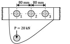
- a) 16.0
- b) 17.2
Correct answer is between ' 16.0, 17.2'. Can you explain this answer?
A component is attached to a horizontal column by means of three identical rivets as shown in figure. The maximum permissible shear stress for the rivets is N mm . The magnitude of maximum force is __________ kN.
a)
16.0
b)
17.2

|
Pathways Academy answered |

Primary direct force,
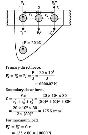
= 6666.67 N
Secondary shear force,

For maximum load,
P1” = P3” = c.r
= 125 x 80 = 10000N
Resultant shear force,
P = P1’ + P1” = 6666.67 + 10000
= 16666.67 N
= 16.7 kN
A circular beam, 50 mm in diameter, is welded to a support by means of a fillet weld as shown in figure. The size of the weld, if the permissible shear stress in the weld is limited to 100N/mm2, is (in mm)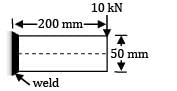
- a) 4 mm
- b) 6 mm
- c) 8 mm
- d) 12 mm
Correct answer is option 'C'. Can you explain this answer?
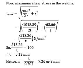
A circular beam, 50 mm in diameter, is welded to a support by means of a fillet weld as shown in figure. The size of the weld, if the permissible shear stress in the weld is limited to 100N/mm2, is (in mm)
a)
4 mm
b)
6 mm
c)
8 mm
d)
12 mm

|
Manish Aggarwal answered |
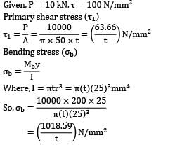
Given, P = 10 kN,T = 100 N/mm2
Primarily shear stress (T1)

Bending stress ( b)
b)
b)
Where, I = πtr3 = π(t)(25)3mm4
Now, maximum shear stress in the weld is;

∴ t = 5.13 mm
Filler material is used in electric resistance welding.- a)Yes
- b)No filler material used
- c)Depends on the type of welding
- d)None of the listed
Correct answer is option 'B'. Can you explain this answer?
Filler material is used in electric resistance welding.
a)
Yes
b)
No filler material used
c)
Depends on the type of welding
d)
None of the listed
|
|
Gayatri Dasgupta answered |
Explanation: No filler material is used. Only the heat released from resistance of metallic parts to current is used for melting the adjoining parts.
Which of the following isn’t a main part of rivet?- a)Head
- b)Shank
- c)Point
- d)Thread
Correct answer is option 'D'. Can you explain this answer?
Which of the following isn’t a main part of rivet?
a)
Head
b)
Shank
c)
Point
d)
Thread
|
|
Saranya Saha answered |
Explanation: There aren’t any threads in rivets.
A bracket, as shown in figure, is welded to a plate. The welds are of same sizeThe value of permissible force per mm of the weld length is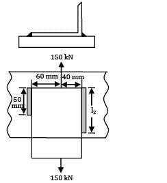

- a) 1 kN
- b) 1.5 kN
- c) 3 kN
- d) 1.2 kN
Correct answer is option 'D'. Can you explain this answer?
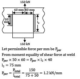
A bracket, as shown in figure, is welded to a plate. The welds are of same size
The value of permissible force per mm of the weld length is
a)
1 kN
b)
1.5 kN
c)
3 kN
d)
1.2 kN

|
Gate Funda answered |

Let permissible force per mm be Pper
From moment equality of shear force at weld
Pper x 50 x 60 = Pper x l2 x 40
l2 = 75 mm
A cast iron bracket, supporting the transmission shaft and the belt pulley, is fixed to the steel structure by means of four bolts as shown in Fig. There are two bolts atA and two bolts atB. The tensions in slack and tight sides of the belt are 5 kN and 10 kN respectively. The belt tensions act in a vertically downward direction. The distances are as follows,l1 = 50 mm, l2 = 150 mm, l = 200 mm The maximum permissible tensile stress in any bolt is 60 N/mm2 . Determine the size of the bolts (in mm2 )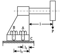
- a) 145
- b) 170
- c) 150
- d) 135
Correct answer is option 'C'. Can you explain this answer?
A cast iron bracket, supporting the transmission shaft and the belt pulley, is fixed to the steel structure by means of four bolts as shown in Fig. There are two bolts at
A and two bolts at
B. The tensions in slack and tight sides of the belt are 5 kN and 10 kN respectively. The belt tensions act in a vertically downward direction. The distances are as follows,
l1 = 50 mm, l2 = 150 mm, l = 200 mm The maximum permissible tensile stress in any bolt is 60 N/mm2 . Determine the size of the bolts (in mm2 )
a)
145
b)
170
c)
150
d)
135

|
Telecom Tuners answered |
Given,P = (5 + 10) kN,
l = 200 mm
 t)max = 60 N/mm2
Tensile stress due to the tendency of bracket to tilt about ‘C’

P1= Cl1, P2 = Cl2
Pl = 2P1l1 + 2P2l2 = 2(Cl1)l1 + 2(Cl2)l2

The maximum force will act on bolts denoted by 2
P2 = Cl2
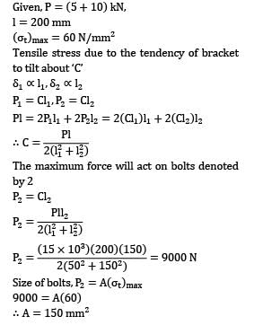
Size of bolts, P2 = A( t)max
t)max
t)max9000 = A(60)
∴A = 150 mm2
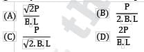
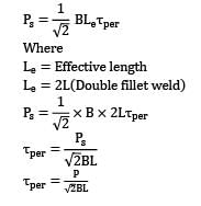
A double fillet welded joint with parallel fillet weld of length L and leg B is subjected to a tensile force P. Assuming uniform stress distribution, the shear stress in the weld is given by- a)

- b)

- c)
- d)

Correct answer is option 'C'. Can you explain this answer?
A double fillet welded joint with parallel fillet weld of length L and leg B is subjected to a tensile force P. Assuming uniform stress distribution, the shear stress in the weld is given by
a)
b)
c)
d)
|
|
Avinash Sharma answered |

Where
Le = Effective length
Le = 2L(Double fillet weld)
.
A circular shaft, 40 mm in diameter, is welded to the support by means of circumferential fillet weld. It is subjected to a torsional moment of 3000 Nm. Permissible shear stress in weld is limited to N mm . The size of weld is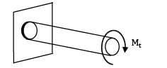
- a) 8 mm
- b) 6 mm
- c) 14 mm
- d) 12 mm
Correct answer is option 'D'. Can you explain this answer?
A circular shaft, 40 mm in diameter, is welded to the support by means of circumferential fillet weld. It is subjected to a torsional moment of 3000 Nm. Permissible shear stress in weld is limited to N mm . The size of weld is
a)
8 mm
b)
6 mm
c)
14 mm
d)
12 mm
|
|
Telecom Tuners answered |
Torsional shear stress in the weld
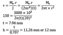
t = 7.96 mm

A shaft of 100 mm diameter is welded to a flat plate by a fillet weld of weld size 16 mm as shown in figure. If the allowable shear stress for the weld material is 50 MPa, the maximum torque the shaft can withstand to avoid weld failure is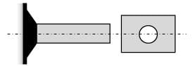
- a) 3.8 丌 kNm
- b) 2.8 丌 kNm
- c) 1.8 丌 kNm
- d) 0.8 丌 kNm
Correct answer is option 'B'. Can you explain this answer?
A shaft of 100 mm diameter is welded to a flat plate by a fillet weld of weld size 16 mm as shown in figure. If the allowable shear stress for the weld material is 50 MPa, the maximum torque the shaft can withstand to avoid weld failure is
a)
3.8 丌 kNm
b)
2.8 丌 kNm
c)
1.8 丌 kNm
d)
0.8 丌 kNm

|
Cstoppers Instructors answered |


= 2.8268π kNm
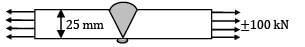
Two plates, 25 mm thick, are welded together by means of a reinforced butt weld and subjected to a completely reversed axial load of 土100kN as shown in figure. The throat of the weld is 25 mm. The ultimate tensile strength of the weld metal is 450N/mm2. The surface finish of the weld is equivalent to that of forged component and the reliability is 90%. The length of the weld is[Assume factor of safety is 2.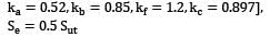
- a) 90 mm
- b) 100 mm
- c) 110 mm
- d) 120 mm
Correct answer is option 'C'. Can you explain this answer?
Two plates, 25 mm thick, are welded together by means of a reinforced butt weld and subjected to a completely reversed axial load of 土100kN as shown in figure. The throat of the weld is 25 mm. The ultimate tensile strength of the weld metal is 450N/mm2. The surface finish of the weld is equivalent to that of forged component and the reliability is 90%. The length of the weld is
[Assume factor of safety is 2.
a)
90 mm
b)
100 mm
c)
110 mm
d)
120 mm
|
|
Cstoppers Instructors answered |
Given, P =  kN, h = 25 mm
kN, h = 25 mmSut = 450N/mm2, R = 90%, FOS = 2
Endurance limit, Se = ka,kb,kc,kd,S’e
For 90% Reliability,kc = 0.897
kd = Modifying factor to account for stress concentration

S’e = 0.5 Sut = 225 MPa
Se = 0.52 x 0.85 x 0.897 x 0.83 x 225
= 74.04 MPa
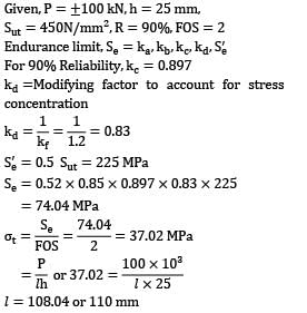
l =108.04 or 110 mm
If the tearing efficiency of a riveted joint is 60%, then the ratio of rivet hole diameter to the pitch of rivets is __________.- a) 0.2
- b) 0.33
- c) 0.4
- d) 0.5
Correct answer is option 'C'. Can you explain this answer?
If the tearing efficiency of a riveted joint is 60%, then the ratio of rivet hole diameter to the pitch of rivets is __________.
a)
0.2
b)
0.33
c)
0.4
d)
0.5
|
|
Meera Bose answered |
Explanation:
Tearing efficiency of a riveted joint:
- Tearing efficiency is the ratio of the net sectional area of the plate to the gross sectional area of the plate.
- It is given as 60%.
Ratio of rivet hole diameter to pitch of rivets:
- The pitch of rivets is the distance between the centerlines of two adjacent rivets in a row.
- Let the diameter of the rivet hole be 'd' and the pitch of rivets be 'p'.
- The net sectional area of the plate is reduced due to the presence of the rivet holes.
- The net sectional area of the plate is (π/4)(d^2) less than the gross sectional area of the plate.
- The tearing efficiency can be expressed as:
Tearing efficiency = [(Gross sectional area - π/4 * d^2) / Gross sectional area] * 100
Given that tearing efficiency = 60%, we have:
60 = [(1 - π/4 * d^2 / Gross sectional area) * 100
Solving for d/p, we get:
d/p = √(4/π * (1 - 0.6))
d/p = √(4/π * 0.4)
d/p = √(1.273)
d/p ≈ 1.13
Therefore, the ratio of rivet hole diameter to the pitch of rivets is approximately 0.4. Hence, the correct answer is option 'C'.
Rails in the field are generally welded by using- a)Thermit welding
- b)Gas welding
- c)Electric arc welding
- d)Forge welding
Correct answer is option 'A'. Can you explain this answer?
Rails in the field are generally welded by using
a)
Thermit welding
b)
Gas welding
c)
Electric arc welding
d)
Forge welding
|
|
Amrita Chauhan answered |
Explanation: Wherever it is uneconomical to carry welding equipments, thermit welding is used.
If force act in a direction parallel to the direction of weld, then fillet weld is called as?- a)Transverse
- b)Longitudinal
- c)Parallel
- d)Longitudinal or Parallel
Correct answer is option 'D'. Can you explain this answer?
If force act in a direction parallel to the direction of weld, then fillet weld is called as?
a)
Transverse
b)
Longitudinal
c)
Parallel
d)
Longitudinal or Parallel

|
Ishaan Kulkarni answered |
Explanation: Parallel fillet weld consist of force acting in a direction of weld.
Hard peening is- a)Hammering the weld across the length while the joint is hot
- b)Hammering the weld along the length while the joint is hot
- c)Hammering the weld along the length while the joint is cold
- d)Hammering the weld across the length while the joint is cold
Correct answer is option 'B'. Can you explain this answer?
Hard peening is
a)
Hammering the weld across the length while the joint is hot
b)
Hammering the weld along the length while the joint is hot
c)
Hammering the weld along the length while the joint is cold
d)
Hammering the weld across the length while the joint is cold
|
|
Hrishikesh Chakraborty answered |
Explanation: Hammering is doe to relieve stresses and inducing compressive stresses to improve the fatigue strength of the joint.
Are the bolts 2 and 3 under same force?- a)Yes
- b)No
- c)Depends on nature of force whether it is of shear or bending in nature
- d)Can’t be determined
Correct answer is option 'B'. Can you explain this answer?
Are the bolts 2 and 3 under same force?
a)
Yes
b)
No
c)
Depends on nature of force whether it is of shear or bending in nature
d)
Can’t be determined

|
Nilanjan Rane answered |
D) Can't be determined without more information
The question does not provide enough information to determine whether bolts 2 and 3 are under the same force. The nature of the force, whether it is shear or bending, can affect how the force is distributed among the bolts.
The question does not provide enough information to determine whether bolts 2 and 3 are under the same force. The nature of the force, whether it is shear or bending, can affect how the force is distributed among the bolts.
The amount by which the two rods to be joined are drawn together is called as?- a)Draw
- b)Portray
- c)Lead
- d)Pitch
Correct answer is option 'A'. Can you explain this answer?
The amount by which the two rods to be joined are drawn together is called as?
a)
Draw
b)
Portray
c)
Lead
d)
Pitch
|
|
Nandini Basak answered |
Answer:
The correct answer is option 'A', draw.
When two rods are joined together, they are usually subjected to an external force or pressure to bring them closer and create a secure connection. The amount by which the two rods are drawn together is called "draw".
Explanation:
In mechanical engineering, joining two rods together can be achieved through various methods such as welding, brazing, or using mechanical fasteners like bolts or screws. In each of these methods, the rods need to be brought together to create a tight joint.
The process of drawing the rods together involves applying force or pressure to overcome any gaps or misalignments between the rods. This force or pressure can be applied through different means depending on the joining method used.
- Welding: In welding, the rods are heated to a molten state, and a filler material is added to create a strong bond between them. During the welding process, the rods are typically clamped or held tightly together using fixtures or clamps to ensure proper alignment. The force applied to bring the rods together is referred to as draw.
- Brazing: Similar to welding, brazing involves heating the rods and using a filler material to join them. In brazing, the rods are usually held together using a jig or clamp, and the force applied to bring them together is called draw.
- Mechanical fastening: When using bolts or screws to join two rods, the force applied to bring the rods together is also referred to as draw. The bolts or screws are tightened using a wrench or other tools, which creates the necessary force to bring the rods into contact and create a secure joint.
In summary, draw refers to the amount of force or pressure applied to bring two rods together during the joining process. It ensures proper alignment and eliminates any gaps or misalignments between the rods, resulting in a secure and durable joint.
Lozenge joint is a kind of lap joint.- a)True
- b)False
Correct answer is option 'B'. Can you explain this answer?
Lozenge joint is a kind of lap joint.
a)
True
b)
False
|
|
Rajat Khanna answered |
Explanation:
Lozenge Joint:
A lozenge joint is a type of lap joint that is used to connect two pieces of material together, typically in woodworking or metalworking. It is named after the diamond-like shape that the joint creates. The lozenge joint is formed by cutting a groove or channel into one piece of material and then fitting the other piece into the groove, creating a flush and secure connection.
Lap Joint:
A lap joint is a type of joint where two pieces of material overlap each other. It is a simple and commonly used joint in woodworking, metalworking, and other applications. The lap joint provides strength and stability by increasing the surface area of contact between the two pieces of material.
Difference between Lozenge Joint and Lap Joint:
The key difference between a lozenge joint and a lap joint is the shape of the joint. While a lozenge joint forms a diamond-like shape, a lap joint does not have any specific shape and can vary depending on the design and requirements of the joint.
Correct Answer:
The correct answer is option 'B' (False) because a lozenge joint is not a type of lap joint. Although both joints are used to connect two pieces of material together, they have different shapes and characteristics. A lozenge joint forms a diamond-like shape, while a lap joint does not have a specific shape. Therefore, a lozenge joint cannot be considered a kind of lap joint.
In summary, a lozenge joint and a lap joint are two different types of joints used in various applications. While a lozenge joint forms a diamond-like shape, a lap joint does not have a specific shape. The statement that a lozenge joint is a kind of lap joint is false.
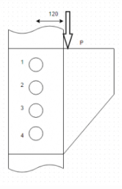
Find the bending stress in the top weld is if thickness of weld is t. Given P=15kN and e=120mm.- a)230/t
- b)360/t
- c)200/t
- d)None of the liste
Correct answer is option 'B'. Can you explain this answer?
Find the bending stress in the top weld is if thickness of weld is t. Given P=15kN and e=120mm.
a)
230/t
b)
360/t
c)
200/t
d)
None of the liste
|
|
Dipika Bose answered |
Explanation: σ=My/I or M=15000×120, y=50 and I=250000t.
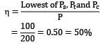
The shear strength, tensile strength and compressive strength of a rivet joint are 100 N, 120 N and 150 N respectively. If strength of the unriveted plate is 200 N, the efficiency of rivet joint is
- a) 60%
- b) 75%
- c) 80%
- d) 50%
Correct answer is option 'D'. Can you explain this answer?
The shear strength, tensile strength and compressive strength of a rivet joint are 100 N, 120 N and 150 N respectively. If strength of the unriveted plate is 200 N, the efficiency of rivet joint is
unriveted plate is 200 N, the efficiency of rivet joint isa)
60%
b)
75%
c)
80%
d)
50%
|
|
Zoya Sharma answered |
Shear strength, PS = 100 N
Tensile strength, Pt = 120 N
Compressive strength, Pc = 190 N
Strength of unriveted plate, P = 200 N
Efficiency of riveted joint is defined as ratio of the strength of riveted joint to the strength of unriveted solid plate.

Two steel rods connected by cotter joint are subjected to 50 kN load each. What is the minimum diameter required of the rods? (Given: Yielding Stress= 400N/mm² ; Factor of Safety=6)- a)31mm
- b)35mm
- c)36mm
- d)40mm
Correct answer is option 'A'. Can you explain this answer?
Two steel rods connected by cotter joint are subjected to 50 kN load each. What is the minimum diameter required of the rods? (Given: Yielding Stress= 400N/mm² ; Factor of Safety=6)
a)
31mm
b)
35mm
c)
36mm
d)
40mm

|
Moumita Dasgupta answered |
To calculate the minimum diameter required for the rods, we need to consider the yield stress of the material and the load applied.
Given:
Yielding Stress = 400 N/mm^2
Load on each rod = 50 kN = 50,000 N
The formula to calculate the minimum diameter required is:
d = sqrt((4 * F) / (π * σ))
Where:
d = diameter of the rod
F = load on each rod
σ = yielding stress
Substituting the values:
d = sqrt((4 * 50,000) / (π * 400))
Calculating further:
d = sqrt(200,000 / (π * 400))
d = sqrt(500 / π)
d ≈ 12.65 mm
Therefore, the minimum diameter required for the rods is approximately 12.65 mm.
The bracket welded to the vertical plate by means of two fillet welds. Calculate the bending stress in the welds if P=40kN, leg=4mm and e=400mm.- a)None of the listed
- b)34N/mm²
- c)24 N/mm²
- d)44 N/mm²
Correct answer is option 'B'. Can you explain this answer?
The bracket welded to the vertical plate by means of two fillet welds. Calculate the bending stress in the welds if P=40kN, leg=4mm and e=400mm.
a)
None of the listed
b)
34N/mm²
c)
24 N/mm²
d)
44 N/mm²
|
|
Samarth Chaudhary answered |
Explanation: σ=My/I where y=250mm,I=2xtx500ᵌ/12 where t=4/.707.
Among gas and electric arc welding, which has the higher rate of heating?- a)Gas welding
- b)Electric arc welding
- c)Gas welding and electric arc welding have equal rate of heating
- d)Cannot be determined
Correct answer is option 'B'. Can you explain this answer?
Among gas and electric arc welding, which has the higher rate of heating?
a)
Gas welding
b)
Electric arc welding
c)
Gas welding and electric arc welding have equal rate of heating
d)
Cannot be determined
|
|
Ameya Kaur answered |
Explanation: Gas welding has a gas temperature of about 3200’C while arc temperature is about 40000’C.
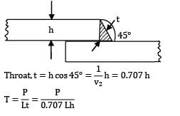
Relation between throat and leg for a parallel fillet weld is- a)t =h Cos (45’)
- b)h =t Cos (45’)
- c)h= t
- d)None of the listed
Correct answer is option 'A'. Can you explain this answer?
Relation between throat and leg for a parallel fillet weld is
a)
t =h Cos (45’)
b)
h =t Cos (45’)
c)
h= t
d)
None of the listed
|
|
Isha Nambiar answered |
Explanation: Throat is the minimum cross section of the weld and that plane lies at 45’ for a parallel fillet weld.
A shaft of diameter D is welded to a plate as shown in figure. A torque T is applied at the free end. If the maximum shear stress produced is given by . Where h is the leg length of weld, then the value of n is __________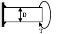
- a) 2.7
- b) 2.9
Correct answer is between ' 2.7, 2.9'. Can you explain this answer?
A shaft of diameter D is welded to a plate as shown in figure. A torque T is applied at the free end. If the maximum shear stress produced is given by . Where h is the leg length of weld, then the value of n is __________
a)
2.7
b)
2.9
|
|
Sarita Yadav answered |

J = lxx + Iyy
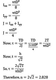

Therefore,n = 2
In a single V-butt welds, the angle between edges is kept about- a) 20 to 400
- b) 40 to 60O
- c) 70 to 90O
- d) 10 to 20O
Correct answer is option 'B'. Can you explain this answer?
In a single V-butt welds, the angle between edges is kept about
a)
20 to 400
b)
40 to 60O
c)
70 to 90O
d)
10 to 20O
|
|
Neha Joshi answered |
In a single V-butt weld, the angle between the edges is kept about. to 60о
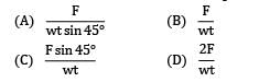
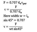
to 60о Two metal plates of thickness ‘t’ and width ‘w’ are joined by a fillet weld of as shown in given figure.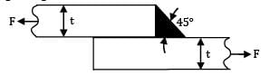 When subjected to a pulling force ‘F’, the stress induced in the weld will be
- a)

- b)

- c)

- d)
Correct answer is option 'A'. Can you explain this answer?
Two metal plates of thickness ‘t’ and width ‘w’ are joined by a fillet weld of as shown in given figure.
When subjected to a pulling force ‘F’, the stress induced in the weld will be
a)
b)
c)
d)

|
Pioneer Academy answered |
Strength of a fillet weld is given by

Here width w = le
Sin 45o = 0.707
Calculate the diameter of the rivets by crushing consideration if permissible compression stress in rivets is 120N/mm², thickness of plate 3mm and P=15kN.- a)10.4mm
- b)11.5mm
- c)9.2mm
- d)8.6mm
Correct answer is option 'A'. Can you explain this answer?
Calculate the diameter of the rivets by crushing consideration if permissible compression stress in rivets is 120N/mm², thickness of plate 3mm and P=15kN.
a)
10.4mm
b)
11.5mm
c)
9.2mm
d)
8.6mm
|
|
Vaibhav Khanna answered |
Introduction
To calculate the diameter of rivets based on crushing considerations, we will use the given values: permissible compression stress, thickness of the plate, and the load applied.
Given Data
- Permissible compression stress (σ) = 120 N/mm²
- Thickness of plate (t) = 3 mm
- Load (P) = 15 kN = 15,000 N
Calculating the Required Area
The area required to support the load can be calculated using the formula:
Area (A) = Load (P) / Permissible stress (σ)
- A = 15,000 N / 120 N/mm²
- A = 125 mm²
Finding the Diameter of the Rivet
The area of a rivet is given by the formula:
A = (π/4) * d²
Where d is the diameter of the rivet.
Rearranging the formula to find the diameter:
d = √(4A/π)
Substituting the area calculated:
- d = √(4 * 125 mm² / π)
- d = √(500 / π)
- d ≈ 10.4 mm
Conclusion
Thus, the diameter of the rivets, considering crushing, should be approximately 10.4 mm. Therefore, the correct answer is option 'A'.
This calculation ensures that the rivets can safely bear the applied load without exceeding the permissible compression stress.
If number of rivets subjected to single shear per pitch length is 2 and those subjected to double shear per pitch length are 3, then find the shear resistance of rivets is diameter of rivets is 20mm and permissible shear 60N/mm².- a)None of the listed
- b)146.1kN
- c)150.7kN
- d)140.2kN
Correct answer is option 'C'. Can you explain this answer?
If number of rivets subjected to single shear per pitch length is 2 and those subjected to double shear per pitch length are 3, then find the shear resistance of rivets is diameter of rivets is 20mm and permissible shear 60N/mm².
a)
None of the listed
b)
146.1kN
c)
150.7kN
d)
140.2kN
|
|
Sharmila Chauhan answered |
Shear Resistance Calculation for Rivets:
Given data:
- Number of rivets subjected to single shear per pitch length = 2
- Number of rivets subjected to double shear per pitch length = 3
- Diameter of rivets = 20mm
- Permissible shear stress = 60N/mm²
Calculations:
1. Area of each rivet in single shear = π*(diameter/2)² = π*(20/2)² = 314.16 mm²
2. Area of each rivet in double shear = 2*π*(diameter/2)² = 2*π*(20/2)² = 628.32 mm²
Shear resistance for single shear:
- Number of rivets in single shear per pitch length = 2
- Total shear resistance in single shear = Number of rivets * Area of each rivet * Permissible shear stress
- Total shear resistance in single shear = 2 * 314.16 * 60 = 37700.8 N
Shear resistance for double shear:
- Number of rivets in double shear per pitch length = 3
- Total shear resistance in double shear = Number of rivets * Area of each rivet * Permissible shear stress
- Total shear resistance in double shear = 3 * 628.32 * 60 = 113197.2 N
Total shear resistance of rivets:
- Total shear resistance = Shear resistance for single shear + Shear resistance for double shear
- Total shear resistance = 37700.8 + 113197.2 = 150898 N = 150.7 kN
Therefore, the shear resistance of the rivets is 150.7 kN. Hence, the correct answer is option 'C'.
Aircraft body is usually fabricated by- a) welding
- b) precasting
- c) riveting
- d) casting
Correct answer is option 'C'. Can you explain this answer?
Aircraft body is usually fabricated by
a)
welding
b)
precasting
c)
riveting
d)
casting
|
|
Sarita Yadav answered |
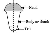
Rivet is a short cylindrical bar with a head with it. It consists of three parts
(A) Head
(B) Body/shank
(C) Tail
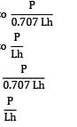
A single parallel fillet weld of total length L and weld size h subjected to a tensile load P, will have what design stress?- a) Tensile is equal to

- b) Tensile is equal to

- c) Shea! and equal to

- d) Shea! and equal to
Correct answer is option 'C'. Can you explain this answer?
A single parallel fillet weld of total length L and weld size h subjected to a tensile load P, will have what design stress?
a)
Tensile is equal to
b)
Tensile is equal to
c)
Shea! and equal to
d)
Shea! and equal to
|
|
Cstoppers Instructors answered |

The circumferential joint of a boiler of diameter 1 m is made of lap joint with rivet diameter of 20 mm. If the allowable shear stress for the material of the rivet is 50 MPa and the boiler has to withstand an internal pressure of 2.5 MPa, then the minimum number of rivets required to prevent the failure of the joint is- a) 150
- b) 125
- c) 100
- d) 75
Correct answer is option 'B'. Can you explain this answer?
The circumferential joint of a boiler of diameter 1 m is made of lap joint with rivet diameter of 20 mm. If the allowable shear stress for the material of the rivet is 50 MPa and the boiler has to withstand an internal pressure of 2.5 MPa, then the minimum number of rivets required to prevent the failure of the joint is
a)
150
b)
125
c)
100
d)
75
|
|
Zoya Sharma answered |

A cylindrical pressure vessel with a 2m wide inside diameter is subjected to internal steam pressure of 1.5Mpa. Calculate the thickness of the plate required if corrosion allowance is considered as 2mm. The permissible value of tensile stress is 80N/mm².- a)15mm
- b)19mm
- c)21mm
- d)17mm
Correct answer is option 'C'. Can you explain this answer?
A cylindrical pressure vessel with a 2m wide inside diameter is subjected to internal steam pressure of 1.5Mpa. Calculate the thickness of the plate required if corrosion allowance is considered as 2mm. The permissible value of tensile stress is 80N/mm².
a)
15mm
b)
19mm
c)
21mm
d)
17mm
|
|
Gaurav Kapoor answered |
Explanation: t=PD/2σ + CA or t=1.5×2000/2×80 + 2.
What is the other name for pitch?- a)Transverse pitch
- b)Back pitch
- c)Row pitch
- d)None of the listed
Correct answer is option 'D'. Can you explain this answer?
What is the other name for pitch?
a)
Transverse pitch
b)
Back pitch
c)
Row pitch
d)
None of the listed
|
|
Anshul Basu answered |
Explanation: Transverse, back and row pitch are all same. It is the distance b/w two consecutive rows of pitch.
 Calculate the primary shear stress on each rivet if P=30kN and diameter of rivets is 15mm.
- a)None of the listed
- b)21.2 N/mm²
- c)42.4N/mm²
- d)169.6 N/mm²
Correct answer is option 'C'. Can you explain this answer?
Calculate the primary shear stress on each rivet if P=30kN and diameter of rivets is 15mm.
a)
None of the listed
b)
21.2 N/mm²
c)
42.4N/mm²
d)
169.6 N/mm²

|
Soul_ Tunes answered |
Primary shear stress(
Τ1
), Τ1=P/(4 A
s
)
Shearing Area for a Single shear,
A
s
=
(π
/4)d^2
=
>
A
s=
(225/4)
π .
Now,
∴
Τ1
=30
x
1000/4
x
(225/4)
π
=
>
Τ1
=42.44
N/mm^2 .
If a circular shaft is welded to the plate by means of circumferential fillet, then the shaft is subjected to torsional moment M. If throat of weld is t, then torsional shear stress is given by- a)M/2πtr²
- b)M/πtr²
- c)M/4πtr²
- d)None of the listed
Correct answer is option 'A'. Can you explain this answer?
If a circular shaft is welded to the plate by means of circumferential fillet, then the shaft is subjected to torsional moment M. If throat of weld is t, then torsional shear stress is given by
a)
M/2πtr²
b)
M/πtr²
c)
M/4πtr²
d)
None of the listed
|
|
Pritam Jain answered |
Explanation: Stress=Mr/J, here J=2πtrᵌ[I(xx)+I(yy)].
The permissible stress in a fillet weld is 100 N/mm2 . The fillet weld has equal leg lengths of 15 mm each. The allowable shearing load on weldment per cm length of the weld is- a) 22.5 kN
- b) 15.0 kN
- c) 10.6 kN
- d) 7.5 kN
Correct answer is option 'C'. Can you explain this answer?
The permissible stress in a fillet weld is 100 N/mm2 . The fillet weld has equal leg lengths of 15 mm each. The allowable shearing load on weldment per cm length of the weld is
a)
22.5 kN
b)
15.0 kN
c)
10.6 kN
d)
7.5 kN
|
|
Neha Joshi answered |
Strength of weld P = 0.707 hlτper

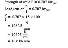
= 10.6 kN/cm
Calculate the thickness of the strap required in longitudinal butt joint if pitch of the rivets is 150mm and diameter of rivets 30mm. Also thickness of plate is 20mm.- a)None of the listed
- b)16.7mm
- c)13.4mm
- d)10.2mm
Correct answer is option 'B'. Can you explain this answer?
Calculate the thickness of the strap required in longitudinal butt joint if pitch of the rivets is 150mm and diameter of rivets 30mm. Also thickness of plate is 20mm.
a)
None of the listed
b)
16.7mm
c)
13.4mm
d)
10.2mm
|
|
Athul Kumar answered |
Explanation: t=0.625t[p-d/p-2d].
The rivets in outer row of longitudinal boiler shell butt joint are subjected to double shear.- a) True
- b)False
Correct answer is option 'B'. Can you explain this answer?
The rivets in outer row of longitudinal boiler shell butt joint are subjected to double shear.
a)
True
b)
False
|
|
Keerthana Joshi answered |
Explanation: Rivets in middle and inner row are subjected to double shear and in outer row are subjected to single shear.
Riveting is not recommended for aluminium alloys.- a)True
- b)False
Correct answer is option 'B'. Can you explain this answer?
Riveting is not recommended for aluminium alloys.
a)
True
b)
False
|
|
Mrinalini Sharma answered |
Why Riveting is not Recommended for Aluminium Alloys
There are several reasons why riveting is not recommended for aluminium alloys.
1. Increased Risk of Galvanic Corrosion:
- Aluminium is a highly reactive metal, and when it comes in contact with other metals, especially in the presence of an electrolyte like moisture, galvanic corrosion can occur.
- Rivets are typically made of steel or other metals, which can lead to galvanic corrosion when in contact with aluminium.
2. Weakening of the Material:
- When a rivet is inserted into an aluminium alloy, it creates stress concentrations around the rivet hole.
- This stress concentration can weaken the material, especially in applications where the aluminium alloy is subjected to dynamic loads or vibrations.
3. Difficulty in Removing Rivets:
- Unlike welding, riveting is a permanent joining method that makes it difficult to disassemble the parts without damaging them.
- If repairs or modifications are needed in the future, removing rivets from aluminium alloys can be challenging and may result in damage to the material.
4. Limited Joint Strength:
- Compared to welding or adhesive bonding, riveted joints may have lower strength and stiffness, especially in critical applications.
- The mechanical properties of the rivet material may not match those of the aluminium alloy, leading to potential joint failures under load.
In conclusion, while riveting can be a cost-effective and efficient joining method for certain materials, it is not recommended for aluminium alloys due to the risk of galvanic corrosion, weakening of the material, difficulty in removal, and limited joint strength. Other joining techniques like welding or adhesive bonding may be more suitable for aluminium alloys to ensure the integrity and longevity of the joined components.
The following bracket is welded to the vertical column. The joint undergoes torsional stresses.- a)True
- b)False
Correct answer is option 'B'. Can you explain this answer?
The following bracket is welded to the vertical column. The joint undergoes torsional stresses.
a)
True
b)
False
|
|
Anshu Patel answered |
Explanation: This joint undergoes bending stresses but not torsional stresses.
How can shock absorbing capacity of a bolt be increased?- a) By tightening it property
- b) By increasing the shank diameter
- c) By grinding the shank
- d) By making the shank diameter equal to the core diameter of thread
Correct answer is option 'D'. Can you explain this answer?
How can shock absorbing capacity of a bolt be increased?
a)
By tightening it property
b)
By increasing the shank diameter
c)
By grinding the shank
d)
By making the shank diameter equal to the core diameter of thread
|
|
Sanvi Kapoor answered |
Making shank diameter equal to the core diameter of thread will increase the strain energy stored in the bolt which will increase the shock absorbing capacity of a bolt.
If length of weld is l and leg h, then area of throat can be given by- a)0.707 hl
- b)1.414hl
- c)hl
- d)None of the listed
Correct answer is option 'A'. Can you explain this answer?
If length of weld is l and leg h, then area of throat can be given by
a)
0.707 hl
b)
1.414hl
c)
hl
d)
None of the listed
|
|
Sparsh Chakraborty answered |
Explanation: Area=t x l where t=h Cos (45’).
The bracket welded to the vertical plate by means of two fillet welds. Calculate size of the welds if P=40kN, leg=4mm and e=400mm. Maximum permissible value of shear stress in the weld is 70N/mm².- a)1.4mm
- b)1.7mm
- c)2.1mm
- d)3mm
Correct answer is option 'C'. Can you explain this answer?
The bracket welded to the vertical plate by means of two fillet welds. Calculate size of the welds if P=40kN, leg=4mm and e=400mm. Maximum permissible value of shear stress in the weld is 70N/mm².
a)
1.4mm
b)
1.7mm
c)
2.1mm
d)
3mm
|
|
Prateek Mukherjee answered |
Explanation: σ=My/I where y=250mm,I=2xtx500ᵌ/12 and τ₁=P/2xtx500.τ=√σ²+τ₁² or 104/t=70 and h=t/0.707.
The thickness of a boiler plate is 16 mm, the diameter of rivet used in the boiler joint is- a) 24 mm
- b) 28 mm
- c) 10 mm
- d) 20 mm
Correct answer is option 'A'. Can you explain this answer?
The thickness of a boiler plate is 16 mm, the diameter of rivet used in the boiler joint is
a)
24 mm
b)
28 mm
c)
10 mm
d)
20 mm
|
|
Avinash Sharma answered |
Thickness of boiler plate,
t = 16mm
Using Unwin’s equation,
Diameter of rivet (d) = 6
= 6 = 24
= 24
= 24 A riveted joint has been designed to support an eccentric load P. The load generates value of equal to 4 kN and equal to 3 kN. The cross-sectional area of each rivet is mm . Consider the following statements1. The stress in the rivet is N mm2. The value of eccentricity L is 100 mm3. The value of load P is 6 kN4. The resultant force in each rivet is 6 kN Which of these statements are correct?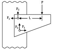
- a) 1 and 2
- b) 2 and 3
- c) 3 and 4
- d) 1 and 3
Correct answer is option 'D'. Can you explain this answer?
A riveted joint has been designed to support an eccentric load P. The load generates value of equal to 4 kN and equal to 3 kN. The cross-sectional area of each rivet is mm . Consider the following statements
1. The stress in the rivet is N mm
2. The value of eccentricity L is 100 mm
3. The value of load P is 6 kN
4. The resultant force in each rivet is 6 kN Which of these statements are correct?
a)
1 and 2
b)
2 and 3
c)
3 and 4
d)
1 and 3
|
|
Telecom Tuners answered |

Given:
F2 = 3 kN
F1 = 4 kN
A = 500 mm2
P = 2F2 = 2 x 3 = 6 kN
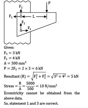
Eccentricity cannot be obtained from the above data.
So, statement 1 and 3 are correct.
Unwin’s formula is used to find _____ of rivets.- a)Diameter
- b)Thickness
- c)Strength
- d)None of the listed
Correct answer is option 'A'. Can you explain this answer?
Unwin’s formula is used to find _____ of rivets.
a)
Diameter
b)
Thickness
c)
Strength
d)
None of the listed
|
|
Ruchi Ahuja answered |
Explanation: d=6√t is unwin’s formula.
Corrosion allowance is the metal removed to reduce the thickness required to withstand internal pressure.- a)True
- b) False
Correct answer is option 'B'. Can you explain this answer?
Corrosion allowance is the metal removed to reduce the thickness required to withstand internal pressure.
a)
True
b)
False
|
|
Keerthana Joshi answered |
Explanation: corrosion allowance is the extra metal added to increase the thickness.
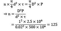
Number of rivets in the circumferential joint can be found by which formula? Symbols have their usual meanings.- a)(D/d)²x2(P/τ)
- b)(D/d)²x(P/τ)
- c)d)²x2(P/τ)b) (D/d)²x(P/τ)
- d)²x2(P/τ)b) (D/d)²x(P/τ)c) (d/D)x(P/τ)d) (D/d)x(P/τ)
Correct answer is option 'B'. Can you explain this answer?
Number of rivets in the circumferential joint can be found by which formula? Symbols have their usual meanings.
a)
(D/d)²x2(P/τ)
b)
(D/d)²x(P/τ)
c)
d)²x2(P/τ)b) (D/d)²x(P/τ)
d)
²x2(P/τ)b) (D/d)²x(P/τ)c) (d/D)x(P/τ)d) (D/d)x(P/τ)
|
|
Pritam Das answered |
Explanation: nx[πd²τ/4]=[πD²/4]xP.
Chapter doubts & questions for Riveted, Bolted & Welded Joints - Design of Machine Elements 2025 is part of Mechanical Engineering exam preparation. The chapters have been prepared according to the Mechanical Engineering exam syllabus. The Chapter doubts & questions, notes, tests & MCQs are made for Mechanical Engineering 2025 Exam. Find important definitions, questions, notes, meanings, examples, exercises, MCQs and online tests here.
Chapter doubts & questions of Riveted, Bolted & Welded Joints - Design of Machine Elements in English & Hindi are available as part of Mechanical Engineering exam.
Download more important topics, notes, lectures and mock test series for Mechanical Engineering Exam by signing up for free.
Design of Machine Elements
49 videos|102 docs|77 tests
|
|
© EduRev
|
Education Revolution
|


|


Signup to see your scores
go up
within 7 days!
within 7 days!
Takes less than 10 seconds to signup