The Inverting Configuration & Non - Free MCQ Practice Test with solutions,
MCQ Practice Test & Solutions: Test: The Inverting Configuration & The Non Inverting Configuration (20 Questions)
You can prepare effectively for Electrical Engineering (EE) Analog and Digital Electronics with this dedicated MCQ Practice Test (available with solutions) on the important topic of "Test: The Inverting Configuration & The Non Inverting Configuration". These 20 questions have been designed by the experts with the latest curriculum of Electrical Engineering (EE) 2026, to help you master the concept.
Test Highlights:
- - Format: Multiple Choice Questions (MCQ)
- - Duration: 20 minutes
- - Number of Questions: 20
Sign up on EduRev for free to attempt this test and track your preparation progress.

When does a resistance provide a negative feedback to an amplifier?
Detailed Solution: Question 1
The effect of the inverting configuration is
Detailed Solution: Question 2

For an ideal negative feedback configuration which of the following is true?
Detailed Solution: Question 3
The negative feedback causes
Detailed Solution: Question 4
The non-inverting closed loop configuration features a high resistance. Therefore in many cases unity gain follower called buffer amplifier is often used to
Detailed Solution: Question 5
The advantage of a weighted summer operational amplifier is
Detailed Solution: Question 6
The following is a circuit of weighted summer capable of summing coefficients of both sign. The expressions for the output voltage v0 is
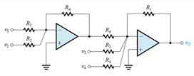
Detailed Solution: Question 7
You are provided with an ideal op amp and three 10kΩ resistors. Using series and parallel resistor combinations, how many different inverting-amplifier circuit topologies are possible?
Detailed Solution: Question 8
The loop gain for an ideal operational amplifier with R1 = 10kΩ and R2(negative feedback) = 1MΩ is
Detailed Solution: Question 9
In an inverting op-amp circuit for which the gain is −4 V/V and the total resistance used is 100 kΩ. Then the value of R1 and R2 (negative feedback)
Detailed Solution: Question 10
In the non-inverting configuration of operational amplifier
Detailed Solution: Question 11
For ideal non-inverting operational amplifier
Detailed Solution: Question 12
For an ideal non-inverting operational amplifier having finite gain (A), the ratio of output voltage (v0) to input voltage (vi) is (given R2 is the feedback resistance)
Detailed Solution: Question 13
The gain for an ideal non-inverting operational amplifier is (given R2 is the feedback resistance)
Detailed Solution: Question 14
While performing an experiment to determine the gain for an ideal operational amplifier having finite gain, a student mistakenly used the equation 1 + R2/R1 where R2 is the feedback resistance. What is the percentage error in his result? Given A is the finite voltage gain of the ideal amplifier used.
Detailed Solution: Question 15
The finite voltage gain of a non-inverting operational amplifier is A and the resistance used is R1 and R2 in which R2 is the feedback resistance. Under what conditions it can one use the expression 1 + R2/R1 to determine the gain of the amplifier?
Detailed Solution: Question 16
Which of the following is not true for a voltage follower amplifier?
Detailed Solution: Question 17
For designing a non-inverting amplifier with a gain of 2 at the maximum output voltage of 10 V and the current in the voltage divider is to be 10 μA the resistance required are R1 and R2where R2 is used to provide negative feedback. Then
Detailed Solution: Question 18
It is required to connect a transducer having an open-circuit voltage of 1 V and a source resistance of 1 MΩ to a load of 1-kΩ resistance. Find the load voltage if the connection is done
Detailed Solution: Question 19
Consider the figure given below. If the resistance R1 is disconnected from the ground and connected to a third power source v3, then expression for the value of v0 is
Detailed Solution: Question 20
135 videos|183 docs|71 tests |