Mechanical Engineering Exam  >  Mechanical Engineering Tests  >  GATE Mechanical (ME) Mock Test Series 2026  >  Test: Bending Moment & Shear Force Diagram - 2 - Mechanical Engineering MCQ

Test: Bending Moment & Shear Force Diagram - 2 - Mechanical Engineering MCQ


Test Description

30 Questions MCQ Test GATE Mechanical (ME) Mock Test Series 2026 - Test: Bending Moment & Shear Force Diagram - 2

Test: Bending Moment & Shear Force Diagram - 2 for Mechanical Engineering 2025 is part of GATE Mechanical (ME) Mock Test Series 2026 preparation. The Test: Bending Moment & Shear Force Diagram - 2 questions and answers have been prepared according to the Mechanical Engineering exam syllabus.The Test: Bending Moment & Shear Force Diagram - 2 MCQs are made for Mechanical Engineering 2025 Exam. Find important definitions, questions, notes, meanings, examples, exercises, MCQs and online tests for Test: Bending Moment & Shear Force Diagram - 2 below.
Solutions of Test: Bending Moment & Shear Force Diagram - 2 questions in English are available as part of our GATE Mechanical (ME) Mock Test Series 2026 for Mechanical Engineering & Test: Bending Moment & Shear Force Diagram - 2 solutions in Hindi for GATE Mechanical (ME) Mock Test Series 2026 course. Download more important topics, notes, lectures and mock test series for Mechanical Engineering Exam by signing up for free. Attempt Test: Bending Moment & Shear Force Diagram - 2 | 30 questions in 90 minutes | Mock test for Mechanical Engineering preparation | Free important questions MCQ to study GATE Mechanical (ME) Mock Test Series 2026 for Mechanical Engineering Exam | Download free PDF with solutions
Test: Bending Moment & Shear Force Diagram - 2 - Question 1

The shear force in a beam subjected to pure positive bending is…… (positive/zero/negative)


Detailed Solution for Test: Bending Moment & Shear Force Diagram - 2 - Question 1

In a beam that is subject to pure positive bending, the shear force is:

  • Zero because bending does not produce any shear force.
Test: Bending Moment & Shear Force Diagram - 2 - Question 2

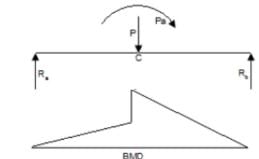
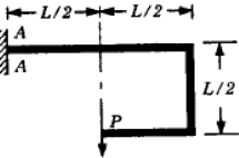
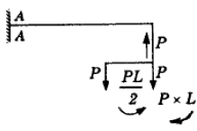
A beam is made up of two identical bars AB and BC, by hinging them together at B. The end A is built-in (cantilevered) and the end C is simply-supported. With the load P acting as shown, the bending moment at A is:

Detailed Solution for Test: Bending Moment & Shear Force Diagram - 2 - Question 2

Given:

  • The beam consists of two bars AB and BC, hinged at B.
  • A is fixed (cantilevered), and C is simply supported.
  • A point load P is applied at midpoint of BC.

Step-by-Step Solution:

  1. Reaction at Support C:

    • Since C is a simple support, it provides a vertical reaction force.

    • Taking moments about C, the reaction at C can be determined as:

      RC × L = P × (L/2)
      RC = P/2

  2. Moment at B due to Reaction at C:

    • The hinge at B does not resist moment, but it transfers force.

    • The moment at B due to reaction at C:

      MB = R_C × L = (P/2) × L = PL/2

  3. Moment at A:

    • Since A is fixed, it must resist the moment coming from B.
    • The moment at A is equal to the moment at B, which is PL/2.

Correct Answer: B (PL/2).

Test: Bending Moment & Shear Force Diagram - 2 - Question 3

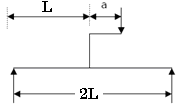
A simply supported beam carries a load 'P' through a bracket, as shown in Figure. The maximum bending moment in the beam is

Detailed Solution for Test: Bending Moment & Shear Force Diagram - 2 - Question 3

option ( c) P1/2 + aP is the correct answer. 

Explanation:- 


Taking moment about Ra

=> P x ½ - Pa + RbI = 0

Or Rb = P/2 = P a/I    therefore, Ra = P/2 - P a/I

Therefore, Mc = Ra x ½ + P x a + Rb x ½    or Mmax = PI /2 + Pa

Test: Bending Moment & Shear Force Diagram - 2 - Question 4

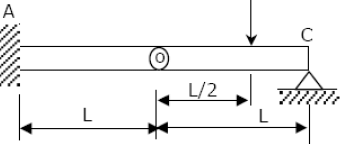
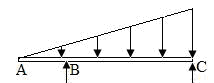
A mass less beam has a loading pattern as shown in the figure. The beam is of rectangular cross -section with a width of 30 mm and height of 100 mm.

The maximum magnitude of bending stress (in MPa) is given by

Detailed Solution for Test: Bending Moment & Shear Force Diagram - 2 - Question 4

Binding stress will be maximum at the outer surface So taking 9 = 50 mm
Moment of Inertia (I):
I = (l d³) / 12

Stress (σ):
σ = (m × 50) / (l d³ / 12)

Moment equation:
mₓ = 1.5 × 10³ [2000 + x] - (x² / 2)

For x = 2500:
m₂₅₀₀ = 3.375 × 10⁶ N·mm

Final stress calculation:
σ = (3.375 × 10⁶ × 50 × 12) / (30 × 10³) = 67.5 MPa

Test: Bending Moment & Shear Force Diagram - 2 - Question 5

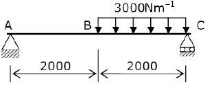
Solve the problems and choose correct answers A steel beam of breadth 120 mm and height 750 mm is loaded as shown in the figure. Assume Esteel= 200 GPa.

The value of maximum deflection of the beam is:

Detailed Solution for Test: Bending Moment & Shear Force Diagram - 2 - Question 5

Moment of inertia (I):
I = (bh³) / 12 = (0.12 × (0.75)³) / 12 = 4.22 × 10⁻³ m⁴

Maximum deflection (δₘₐₓ):
δₘₐₓ = (5 / 384) × (wL⁴ / EI)
= (5 / 384) × (120 × 10³ × 15⁴) / (200 × 10⁹ × 4.22 × 10⁻³) m
= 93.75 mm

Test: Bending Moment & Shear Force Diagram - 2 - Question 6

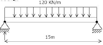
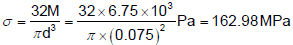
A simply supported beam of span length 6m and 75mm diameter carries a uniformly distributed load of 1.5 kN/m

What is the maximum value of bending stress?

Detailed Solution for Test: Bending Moment & Shear Force Diagram - 2 - Question 6

Test: Bending Moment & Shear Force Diagram - 2 - Question 7

A simply supported beam of length 'l' is subjected to a symmetrical uniformly varying load with zero intensity at the ends and intensity w (load per unit length) at the mid span. What is the maximum bending moment?

Detailed Solution for Test: Bending Moment & Shear Force Diagram - 2 - Question 7

Given:

  • A simply supported beam of length L.
  • A symmetrical uniformly varying load (zero at ends and maximum w at mid-span).

Step-by-Step Solution:

  1. Nature of Load:

    • The given load is a parabolic (triangular) distributed load.
    • The maximum bending moment occurs at mid-span.
  2. Formula for Maximum Bending Moment:

    • The standard formula for a simply supported beam with a parabolic (triangular) load distribution is:

      M_max = (wL²) / 12.

  3. Comparison with Given Options:

    • Option B: (wL²) / 12 matches the formula.

Correct Answer: B.

Test: Bending Moment & Shear Force Diagram - 2 - Question 8

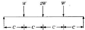
A beam subjected to a load P is shown in the given figure. The bending moment at the support AA of the beam will be

Detailed Solution for Test: Bending Moment & Shear Force Diagram - 2 - Question 8

Load P at end produces moment PL/2 in anticlockwise direction. Load P at end produces moment of PL in clockwise direction. Net moment at AA is PL/2.

Test: Bending Moment & Shear Force Diagram - 2 - Question 9

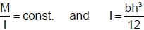
A rectangular section beam subjected to a bending moment M varying along its length is required to develop same maximum bending stress at any cross-section. If the depth of the section is constant, then its width will vary as

Detailed Solution for Test: Bending Moment & Shear Force Diagram - 2 - Question 9

Test: Bending Moment & Shear Force Diagram - 2 - Question 10

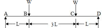
A cantilever beam having 5 m length is so loaded that it develops a shearing force of 20T and a bending moment of 20 T-m at a section 2m from the free end. Maximum shearing force and maximum bending moment developed in the beam under this load are respectively 50 T and 125 T-m. The load on the beam is:

Detailed Solution for Test: Bending Moment & Shear Force Diagram - 2 - Question 10

The solution involves determining the type of load applied to a cantilever beam based on given shearing forces and bending moments.

  • The maximum shearing force is 50 T, and the maximum bending moment is 125 T-m.

  • At 2 m from the free end, the beam experiences a shearing force of 20 T and a bending moment of 20 T-m.

  • Given these conditions, the load that fits the description is a 10 T/m uniform distributed load (udl) over the entire beam length.

Test: Bending Moment & Shear Force Diagram - 2 - Question 11

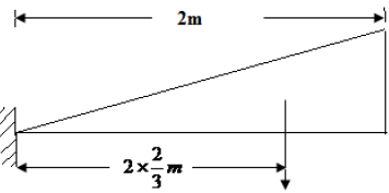
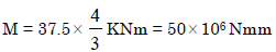
A cantilever beam of 2m length supports a triangularly distributed load over its entire length, the maximum of which is at the free end. The total load is 37.5 kN.What is the bending moment at the fixed end?

Detailed Solution for Test: Bending Moment & Shear Force Diagram - 2 - Question 11

Test: Bending Moment & Shear Force Diagram - 2 - Question 12

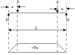
Assertion (A): If the bending moment diagram is a rectangle, it indicates that the beam is loaded by a uniformly distributed moment all along the length.

Reason (R): The BMD is a representation of internal forces in the beam and not the moment applied on the beam.

Detailed Solution for Test: Bending Moment & Shear Force Diagram - 2 - Question 12
  • The assertion that if the bending moment diagram (BMD) is a rectangle, it means the beam is loaded by a uniformly distributed moment along its length, is false.
  • A rectangular BMD typically indicates a constant moment, which is not due to a uniformly distributed moment but rather a constant bending moment applied.
  • The reason that the BMD is a representation of internal forces in the beam, not the moment applied, is true. The BMD shows how internal bending moments vary along the length of the beam.
  • Therefore, the correct choice is D: Assertion is false, but the Reason is true.
Test: Bending Moment & Shear Force Diagram - 2 - Question 13

A simply supported beam is loaded as shown in the above figure. The maximum shear force in the beam will be

Detailed Solution for Test: Bending Moment & Shear Force Diagram - 2 - Question 13

To determine the maximum shear force in the given simply supported beam with point loads (W, 2W, W), we follow these steps:

Step-by-Step Solution:
Total Load on the Beam
:

  • The applied point loads are: W at one point, 2W at another, and W at another.
  • Total applied load = W + 2W + W = 4W.

Reaction Forces at Supports:

  • Since the beam is symmetrically loaded, the reactions at both supports will be equal.
  • Each support carries half of the total load:
    • Reaction at each support = (4W / 2) = 2W.

Shear Force Calculation:

  • The shear force starts from the left support (2W upward).
  • Moving from left to right:
    • At the first point load (W), shear force = 2W - W = W.
    • At the second point load (2W), shear force = W - 2W = -W.
    • At the third point load (W), shear force = -W - W = -2W.
  • The maximum absolute shear force in the beam is 2W.

Correct Answer: C (2W).

Test: Bending Moment & Shear Force Diagram - 2 - Question 14

Constant bending moment over span "l " will occur in

Detailed Solution for Test: Bending Moment & Shear Force Diagram - 2 - Question 14

To achieve a constant bending moment over a span, the applied forces must create a condition where the bending moment does not change along that segment.

Step-by-Step Analysis:

  1. Understanding Constant Bending Moment:

    • A constant bending moment occurs when no shear force is present along the span.
    • This happens when the span is subjected to equal and opposite moments at both ends without any intermediate forces.
  2. Examining the Given Options:

    • Option A: A cantilever beam with a point load at the end creates a varying bending moment. (Incorrect)
    • Option B: A simply supported beam with a central load creates a triangular bending moment distribution. (Incorrect)
    • Option C: A beam with fixed supports and a central point load still produces a varying bending moment. (Incorrect)
    • Option D: A beam subjected to equal and opposite moments (W) at both ends results in a constant bending moment across the span. (Correct)

Since constant bending moment occurs in a beam subjected to equal and opposite moments at both ends, the correct answer is:

D.

Test: Bending Moment & Shear Force Diagram - 2 - Question 15

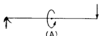
A beam is simply supported at its ends and is loaded by a couple at its mid -span as shown in figure A. Shear force diagram for the beam is given by the figure.

Detailed Solution for Test: Bending Moment & Shear Force Diagram - 2 - Question 15

For a simply supported beam subjected to a couple (moment) at mid-span, the shear force distribution follows a specific pattern.

Step-by-Step Analysis:

  1. Reaction Forces at Supports:

    • A pure moment (couple) does not create vertical reactions at the supports.
    • The shear force remains zero throughout the beam because there are no external transverse forces acting.
  2. Shear Force Diagram:

    • Since no vertical force exists, the shear force at every section remains zero.
    • The correct shear force diagram should be a zero-value horizontal line.
  3. Matching with Given Options:

    • Option B: Triangular shape (Incorrect).
    • Option C: Discontinuous step diagram (Incorrect).
    • Option D: Linear variation (Incorrect).
    • Option E: A horizontal line at zero shear force (Correct).

Since the correct shear force diagram is a zero shear force line, the correct answer is:

D: E.

Test: Bending Moment & Shear Force Diagram - 2 - Question 16

A beam having uniform cross-section carries a uniformly distributed load of intensity q per unit length over its entire span, and its mid-span deflection is δ.

The value of mid-span deflection of the same beam when the same load is distributed with intensity varying from 2q unit length at one end to zero at the other end is:

Detailed Solution for Test: Bending Moment & Shear Force Diagram - 2 - Question 16

For a simply supported beam with a uniformly distributed load (UDL) of intensity q, the mid-span deflection is given as δ.

Now, when the same load is changed to a triangularly varying load from 2q at one end to zero at the other end, the mid-span deflection is compared.

Step-by-Step Analysis:

  1. Deflection for Uniform Load:

    • A uniformly distributed load (UDL) creates a parabolic bending moment diagram and the mid-span deflection is δ.
  2. Deflection for Triangularly Varying Load:

    • A triangularly varying load creates a different bending moment distribution.
    • When the load varies linearly from 2q at one end to 0 at the other end, the mid-span deflection remains the same as that for a uniform UDL of intensity q.
    • This is a known result from beam deflection theory.

Thus, the mid-span deflection remains δ, and the correct answer is:

D: δ.

Test: Bending Moment & Shear Force Diagram - 2 - Question 17

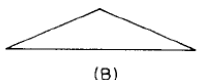
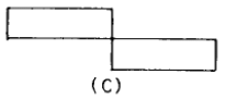
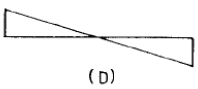
The bending moment diagram shown in Fig. I correspond to the shear force diagram in 

Detailed Solution for Test: Bending Moment & Shear Force Diagram - 2 - Question 17

If shear force is zero, B.M. will also be zero. If shear force varies linearly with length, B.M. diagram will be curved line.

Test: Bending Moment & Shear Force Diagram - 2 - Question 18

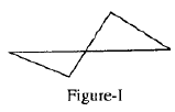
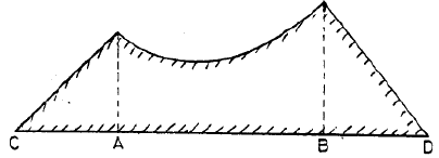
Figure shown above represents the BM diagram for a simply supported beam. The beam is subjected to which one of the following? 

Detailed Solution for Test: Bending Moment & Shear Force Diagram - 2 - Question 18

The given bending moment (BM) diagram shows a sudden jump at the mid-span of a simply supported beam.

  1. Understanding the BM Diagram:

    • The sudden jump in the bending moment at the mid-span indicates the presence of a couple (moment) applied at that point.
    • In a simply supported beam, a concentrated force would create a triangular BM diagram, and a uniformly distributed load would create a parabolic BM diagram.
    • The presence of a sharp change (discontinuity) in the BM diagram suggests an external moment (couple) is applied at the midpoint.
  2. Analyzing the Options:

    • Option A: A concentrated load at mid-length would create a triangular bending moment diagram. (Incorrect)
    • Option B: A uniformly distributed load would create a parabolic bending moment diagram. (Incorrect)
    • Option C: A couple at the mid-length causes an instant jump in the bending moment diagram. (Correct)
    • Option D: A couple at 1/4th span would create jumps at two different locations, which is not shown in the diagram. (Incorrect)

Since the diagram represents a sudden change in bending moment at mid-length, the correct answer is:

C: A couple at its mid-length.

Test: Bending Moment & Shear Force Diagram - 2 - Question 19

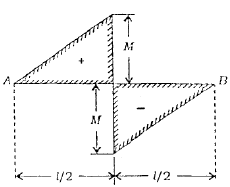
The figure given below shows a bending moment diagram for the beam CABD:

Load diagram for the above beam will be:

Detailed Solution for Test: Bending Moment & Shear Force Diagram - 2 - Question 19

Load diagram at (a) is correct because B.M. diagram between A and B is parabola which is possible with uniformly distributed load in this region.

Test: Bending Moment & Shear Force Diagram - 2 - Question 20

 Which one of the following is NOT a statically indeterminate structure?

Detailed Solution for Test: Bending Moment & Shear Force Diagram - 2 - Question 20

A statically indeterminate structure is one where the number of unknown reaction forces exceeds the number of available equilibrium equations (∑Fx = 0, ∑Fy = 0, ∑M = 0).

  1. Option A: The structure is fixed at both ends, which introduces more reaction components than available equilibrium equations, making it statically indeterminate.
  2. Option B: A fixed beam with multiple supports has additional constraints, making it statically indeterminate.
  3. Option C: This is a determinate structure because it consists of a bent member with only necessary constraints, allowing it to be solved using equilibrium equations alone.
  4. Option D: A composite beam with two materials introduces additional compatibility conditions, making it statically indeterminate.

Since option C is the only determinate structure, the correct answer is: C.

Test: Bending Moment & Shear Force Diagram - 2 - Question 21

Assertion (A): The change in bending moment between two cross-sections of a beam is equal to the area of the shearing force diagram between the two sections.

Reason (R): The change in the shearing force between two cross-sections of beam due to distributed loading is equal to the area of the load intensity diagram between the two sections.

Detailed Solution for Test: Bending Moment & Shear Force Diagram - 2 - Question 21
  • The assertion that the change in bending moment between two cross-sections of a beam is equal to the area of the shearing force diagram between those sections is true.

  • The reason states that the change in shearing force between two sections due to distributed loading equals the area of the load intensity diagram between them. This statement is also true.

  • However, the reason provided does not explain the assertion. The change in bending moment is related to the area under the shearing force diagram, but the change in shearing force relates to the area under the load intensity diagram.

Therefore, both statements are correct, but the reason does not explain the assertion.

Test: Bending Moment & Shear Force Diagram - 2 - Question 22

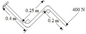
A load perpendicular to the plane of the handle is applied at the free end as shown in the given figure. The values of Shear Forces (S.F.), Bending Moment (B.M.) and torque at the fixed end of the handle have been determined respectively as 400 N, 340 Nm and 100  by a student. Among these values, those of

Detailed Solution for Test: Bending Moment & Shear Force Diagram - 2 - Question 22

SF = 400N and BM = 400 × (0.4 + 0.2) = 240Nm
Torque = 400 × 0.25 = 100Nm

Test: Bending Moment & Shear Force Diagram - 2 - Question 23

The beam is loaded as shown in Fig. I. Select the correct B.M. diagram

Detailed Solution for Test: Bending Moment & Shear Force Diagram - 2 - Question 23

The given beam is subjected to a triangularly distributed load, which starts from zero at A and increases linearly towards C.

  1. The shear force diagram for a beam with a triangular load is parabolic in nature.
  2. The bending moment diagram is obtained by integrating the shear force diagram.
  3. For a triangularly varying load, the bending moment diagram takes a cubic shape.
  4. The maximum bending moment occurs at a certain point between A and C.
  5. The correct Bending Moment (B.M.) diagram must be a smooth cubic curve.

From the given options, Option D correctly represents a cubic bending moment diagram.

Correct answer: D.

Test: Bending Moment & Shear Force Diagram - 2 - Question 24

For the shear force to be uniform throughout the span of a simply supported beam, it should carry which one of the following loadings?

Detailed Solution for Test: Bending Moment & Shear Force Diagram - 2 - Question 24

It is a case of pure bending. 

Test: Bending Moment & Shear Force Diagram - 2 - Question 25

Which one of the following figures represents the correct shear force diagram for the loaded beam shown in the given figure I?

Detailed Solution for Test: Bending Moment & Shear Force Diagram - 2 - Question 25

Given Problem:

  • A simply supported beam with two point loads (W) placed symmetrically.
  • Beam span L + 3L + L = 5L.
  • Loads are applied at points B and C.

Step-by-Step Solution:
Reaction Forces at Supports (A and D):

  • The beam is symmetrical, so reactions at A and D will be equal.
  • Total downward force = W + W = 2W.
  • Due to symmetry, reaction at A and D = W each.

Shear Force Calculation:

  • From A to B (Left side of B):
  • Shear force = W (upward at A, no other force till B).

Just Right of B:
A downward force W at B reduces the shear force to 0.

From B to C (Between Loads):
No additional force, so shear force remains 0.

Just Right of C:
A downward force W at C decreases the shear force to -W.

From C to D (Right side of C):
Shear force remains -W until D.

At D (Right Support):
Reaction +W at D brings the shear force back to 0.

Shear Force Diagram Shape:

  • Flat horizontal segments where no force is acting.
  • Vertical jumps at points of applied loads (B and C).

Correct Option:
Option A correctly shows a stepwise shear force diagram with discontinuities at B and C.
Other options show inclined or incorrect force distributions.
Final Answer: A.

Test: Bending Moment & Shear Force Diagram - 2 - Question 26

A simply supported beam of span l is subjected to a uniformly varying load having zero intensity at the left support and w N/m at the right support. The reaction at the right support is:

Detailed Solution for Test: Bending Moment & Shear Force Diagram - 2 - Question 26

Given:

  • A simply supported beam of span L.
  • A uniformly varying load that starts from zero at the left support and increases linearly to w N/m at the right support.

Step-by-step solution:

  1. Total Load Calculation
    The total uniformly varying load (UVL) is equivalent to a triangular load with:

    • Base = L (beam span)
    • Height = w (maximum intensity at the right end)

    The total load WWW due to this UVL is:

    W = (1/2) × base × height
    W = (1/2) × L × w
    W = wL / 2

  2. Load Acting Position

    • The centroid of a triangular load acts at 1/3 of the base from the larger end (right support).
    • So, the equivalent point load acts at L/3 from the right support.
  3. Reaction Calculation

    • Let R₁ be the reaction at the left support.

    • Let R₂ be the reaction at the right support.

    • Using moment equilibrium about the left support (taking moments about A):

      R₂ × L = (wL/2) × (L/3)
      R₂ × L = (wL² / 6)
      R₂ = (wL / 3)

Thus, the reaction at the right support is wL / 3.

Test: Bending Moment & Shear Force Diagram - 2 - Question 27

A point, along the length of a beam subjected to loads, where bending moment changes its sign, is known as the point of

Detailed Solution for Test: Bending Moment & Shear Force Diagram - 2 - Question 27

The point along a beam where the bending moment changes sign is known as the point of contra flexure. At this point:

  • The bending moment is zero.
  • The beam changes from sagging to hogging or vice versa.
  • It is significant in structural analysis for determining stress distribution.
Test: Bending Moment & Shear Force Diagram - 2 - Question 28

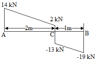
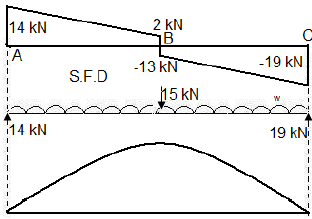
The shear force diagram of a loaded beam is shown in the following figure: The maximum Bending Moment of the beam is:

Detailed Solution for Test: Bending Moment & Shear Force Diagram - 2 - Question 28

Test: Bending Moment & Shear Force Diagram - 2 - Question 29

The bending moment diagram for a simply supported beam is a rectangle over a larger portion of the span except near the supports. What type of load does the beam carry?

Detailed Solution for Test: Bending Moment & Shear Force Diagram - 2 - Question 29

The bending moment diagram for a simply supported beam is rectangular over most of its span, except near the supports. This indicates the type of load the beam carries:

  • The beam carries two identical concentrated loads.
  • These loads are placed equidistant from the mid-span and close to the supports.

This configuration results in a constant bending moment in the central portion, explaining the rectangular shape of the diagram.

Test: Bending Moment & Shear Force Diagram - 2 - Question 30

Assertion (A): In a loaded beam, if the shear force diagram is a straight line parallel to the beam axis,  then the bending moment is a straight line inclined to the beam axis.

Reason (R): When shear force at any section of a beam is zero or changes sign, the bending moment  at that section is maximum.

Detailed Solution for Test: Bending Moment & Shear Force Diagram - 2 - Question 30

Let's analyze both statements:
Assertion (A):

If the shear force diagram is a straight line parallel to the beam axis, this implies a linear variation in shear force along the length of the beam.

The bending moment is related to the shear force through the equation:
M(x) = ∫V(x)dx

If the shear force is constant (a straight line parallel to the beam axis), the bending moment would vary as a straight line (since its derivative, the shear force, is constant).

Thus, Assertion A is true.

Reason (R):

The shear force at any section being zero or changing sign implies that the bending moment at that section is either maximum or minimum. This is because at the points where shear force changes sign (zero shear force), the bending moment typically reaches its maximum (or minimum) value.
Thus, Reason R is true.

Correct explanation:
The reason provided explains why the bending moment would be maximum where the shear force is zero or changes sign.
Therefore, both A and R are individually true, and R is the correct explanation of A.
The correct answer is B.

30 docs|220 tests
Information about Test: Bending Moment & Shear Force Diagram - 2 Page
In this test you can find the Exam questions for Test: Bending Moment & Shear Force Diagram - 2 solved & explained in the simplest way possible. Besides giving Questions and answers for Test: Bending Moment & Shear Force Diagram - 2, EduRev gives you an ample number of Online tests for practice
Download as PDF