


Electrical Engineering (EE) Exam > Electrical Engineering (EE) Questions > The theoretical maximum efficiency of a bridg...
Start Learning for Free
The theoretical maximum efficiency of a bridge rectifier circuit is
- a)48.2%
- b)40.53%
- c)81.06%
- d)82%
Correct answer is option 'C'. Can you explain this answer?

Most Upvoted Answer
The theoretical maximum efficiency of a bridge rectifier circuit isa)4...
For a bridge rectifier circuit,
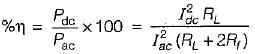
For ideal diode,
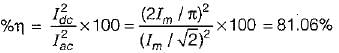
and hence maximum efficiency, η = 81.06%.
For ideal diode,
and hence maximum efficiency, η = 81.06%.
Free Test
FREE
| Start Free Test |
Community Answer
The theoretical maximum efficiency of a bridge rectifier circuit isa)4...
Bridge Rectifier Circuit Efficiency
The bridge rectifier circuit is a widely used circuit that converts AC voltage into DC voltage. The efficiency of a rectifier circuit is the ratio of DC output power to the AC input power. The theoretical maximum efficiency of a bridge rectifier circuit can be calculated by assuming ideal diodes and no voltage drops in the circuit.
Calculation of Maximum Efficiency
The bridge rectifier circuit consists of four diodes that are arranged in a bridge configuration. The AC voltage is applied to the input of the circuit and the output voltage is taken across the load resistor. The maximum efficiency of the circuit can be calculated as follows:
Efficiency, η = (DC output power / AC input power) x 100%
DC output power = (Vdc2 / (2R))
where Vdc = maximum DC voltage across the load resistor and R = load resistor
AC input power = (Vrms2 / R)
where Vrms = RMS voltage of the AC input voltage
Substituting the above equations in the efficiency equation, we get:
η = (Vdc2 / (2R)) / (Vrms2 / R) x 100%
η = (Vdc2 / (2Vrms2)) x 100%
In an ideal bridge rectifier circuit, the maximum DC voltage across the load resistor is equal to the peak voltage of the AC input, which is Vp = √2 x Vrms. Substituting this value in the above equation, we get:
η = (Vp / (2Vrms))2 x 100%
η = (0.5)2 x 100%
η = 25%
However, in a practical circuit, there are voltage drops across the diodes, which reduces the maximum DC voltage across the load resistor. This reduces the efficiency of the circuit. The practical maximum efficiency of a bridge rectifier circuit is around 81.06%.
Therefore, the correct option is (c) 81.06%.

|
Explore Courses for Electrical Engineering (EE) exam
|
|
Top Courses for Electrical Engineering (EE)View all


Question Description
The theoretical maximum efficiency of a bridge rectifier circuit isa)48.2%b)40.53%c)81.06%d)82%Correct answer is option 'C'. Can you explain this answer? for Electrical Engineering (EE) 2025 is part of Electrical Engineering (EE) preparation. The Question and answers have been prepared according to the Electrical Engineering (EE) exam syllabus. Information about The theoretical maximum efficiency of a bridge rectifier circuit isa)48.2%b)40.53%c)81.06%d)82%Correct answer is option 'C'. Can you explain this answer? covers all topics & solutions for Electrical Engineering (EE) 2025 Exam. Find important definitions, questions, meanings, examples, exercises and tests below for The theoretical maximum efficiency of a bridge rectifier circuit isa)48.2%b)40.53%c)81.06%d)82%Correct answer is option 'C'. Can you explain this answer?.
The theoretical maximum efficiency of a bridge rectifier circuit isa)48.2%b)40.53%c)81.06%d)82%Correct answer is option 'C'. Can you explain this answer? for Electrical Engineering (EE) 2025 is part of Electrical Engineering (EE) preparation. The Question and answers have been prepared according to the Electrical Engineering (EE) exam syllabus. Information about The theoretical maximum efficiency of a bridge rectifier circuit isa)48.2%b)40.53%c)81.06%d)82%Correct answer is option 'C'. Can you explain this answer? covers all topics & solutions for Electrical Engineering (EE) 2025 Exam. Find important definitions, questions, meanings, examples, exercises and tests below for The theoretical maximum efficiency of a bridge rectifier circuit isa)48.2%b)40.53%c)81.06%d)82%Correct answer is option 'C'. Can you explain this answer?.
Solutions for The theoretical maximum efficiency of a bridge rectifier circuit isa)48.2%b)40.53%c)81.06%d)82%Correct answer is option 'C'. Can you explain this answer? in English & in Hindi are available as part of our courses for Electrical Engineering (EE).
Download more important topics, notes, lectures and mock test series for Electrical Engineering (EE) Exam by signing up for free.
Here you can find the meaning of The theoretical maximum efficiency of a bridge rectifier circuit isa)48.2%b)40.53%c)81.06%d)82%Correct answer is option 'C'. Can you explain this answer? defined & explained in the simplest way possible. Besides giving the explanation of
The theoretical maximum efficiency of a bridge rectifier circuit isa)48.2%b)40.53%c)81.06%d)82%Correct answer is option 'C'. Can you explain this answer?, a detailed solution for The theoretical maximum efficiency of a bridge rectifier circuit isa)48.2%b)40.53%c)81.06%d)82%Correct answer is option 'C'. Can you explain this answer? has been provided alongside types of The theoretical maximum efficiency of a bridge rectifier circuit isa)48.2%b)40.53%c)81.06%d)82%Correct answer is option 'C'. Can you explain this answer? theory, EduRev gives you an
ample number of questions to practice The theoretical maximum efficiency of a bridge rectifier circuit isa)48.2%b)40.53%c)81.06%d)82%Correct answer is option 'C'. Can you explain this answer? tests, examples and also practice Electrical Engineering (EE) tests.
|
|
Explore Courses for Electrical Engineering (EE) exam
|
|

Signup for Free!
Signup to see your scores go up within 7 days! Learn & Practice with 1000+ FREE Notes, Videos & Tests.
|
© EduRev
|
Education Revolution
|


|


Signup on EduRev and stay on top of your study goals
10M+ students crushing their study goals daily