


Electrical Engineering (EE) Exam > Electrical Engineering (EE) Questions > Calculate the power factor of a series RL cir... Start Learning for Free
Calculate the power factor of a series RL circuit having the conductance of 30 Siemens and the susceptance of 40 Siemens.
- a)0.2
- b)0.4
- c)0.6
- d)0.8
Correct answer is option 'C'. Can you explain this answer?

Most Upvoted Answer
Calculate the power factor of a series RL circuit having the conductan...
Concept:
The admittance triangle is also represented similarly to the impedance triangle. As the impedance (Z) of the circuit has two rectangular components, resistance (R) and reactance (X).
Similarly, admittance (Y) also has two components, conductance (G) and susceptance (B).
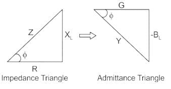
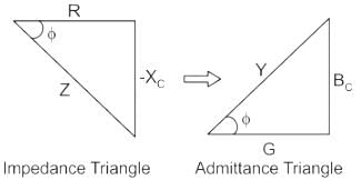
Then Power factor will be:
PF = cosθ = G/Y
Calculation:
Given;
G = 30 siemens
B = 40 Siemens
Y = √(302 + 402) = 50 Siemens
PF = cosθ = 30/50 = 0.6
Free Test
FREE
| Start Free Test |
Community Answer
Calculate the power factor of a series RL circuit having the conductan...
To calculate the power factor of a series RL circuit, we need to understand the concept of conductance and susceptance.
1. Conductance:
Conductance, denoted by G, is the reciprocal of resistance. It represents the ease with which current can flow through a circuit. The unit of conductance is Siemens (S).
2. Susceptance:
Susceptance, denoted by B, is the reciprocal of reactance. It represents the ease with which an alternating current can flow through a circuit. The unit of susceptance is also Siemens (S).
Given:
Conductance (G) = 30 S
Susceptance (B) = 40 S
Now, the power factor (PF) of a series RL circuit can be calculated using the following formula:
PF = G / √(G^2 + B^2)
Substituting the given values into the formula:
PF = 30 / √(30^2 + 40^2)
= 30 / √(900 + 1600)
= 30 / √(2500)
= 30 / 50
= 0.6
Therefore, the power factor of the series RL circuit is 0.6.
Explanation:
In a series RL circuit, the power factor is determined by the ratio of the conductance to the square root of the sum of the squares of conductance and susceptance. Conductance represents the real or active power component of the circuit, while susceptance represents the reactive power component.
A power factor of 0.6 indicates that the circuit has a combination of both active and reactive power. It implies that the circuit is not purely resistive but has a certain amount of inductive or capacitive reactance.
A higher power factor (closer to 1) indicates a circuit with less reactive power and more active power. A lower power factor (closer to 0) indicates a circuit with more reactive power and less active power.
Therefore, in this case, the power factor is 0.6, indicating that the series RL circuit has both resistive and reactive components.
 | Explore Courses for Electrical Engineering (EE) exam |
Top Courses for Electrical Engineering (EE)View all


Top Courses for Electrical Engineering (EE)
Question Description
Calculate the power factor of a series RL circuit having the conductance of 30 Siemens and the susceptance of 40 Siemens.a)0.2b)0.4c)0.6d)0.8Correct answer is option 'C'. Can you explain this answer? for Electrical Engineering (EE) 2026 is part of Electrical Engineering (EE) preparation. The Question and answers have been prepared according to the Electrical Engineering (EE) exam syllabus. Information about Calculate the power factor of a series RL circuit having the conductance of 30 Siemens and the susceptance of 40 Siemens.a)0.2b)0.4c)0.6d)0.8Correct answer is option 'C'. Can you explain this answer? covers all topics & solutions for Electrical Engineering (EE) 2026 Exam. Find important definitions, questions, meanings, examples, exercises and tests below for Calculate the power factor of a series RL circuit having the conductance of 30 Siemens and the susceptance of 40 Siemens.a)0.2b)0.4c)0.6d)0.8Correct answer is option 'C'. Can you explain this answer?.
Calculate the power factor of a series RL circuit having the conductance of 30 Siemens and the susceptance of 40 Siemens.a)0.2b)0.4c)0.6d)0.8Correct answer is option 'C'. Can you explain this answer? for Electrical Engineering (EE) 2026 is part of Electrical Engineering (EE) preparation. The Question and answers have been prepared according to the Electrical Engineering (EE) exam syllabus. Information about Calculate the power factor of a series RL circuit having the conductance of 30 Siemens and the susceptance of 40 Siemens.a)0.2b)0.4c)0.6d)0.8Correct answer is option 'C'. Can you explain this answer? covers all topics & solutions for Electrical Engineering (EE) 2026 Exam. Find important definitions, questions, meanings, examples, exercises and tests below for Calculate the power factor of a series RL circuit having the conductance of 30 Siemens and the susceptance of 40 Siemens.a)0.2b)0.4c)0.6d)0.8Correct answer is option 'C'. Can you explain this answer?.
Solutions for Calculate the power factor of a series RL circuit having the conductance of 30 Siemens and the susceptance of 40 Siemens.a)0.2b)0.4c)0.6d)0.8Correct answer is option 'C'. Can you explain this answer? in English & in Hindi are available as part of our courses for Electrical Engineering (EE). Download more important topics, notes, lectures and mock test series for Electrical Engineering (EE) Exam by signing up for free.
Here you can find the meaning of Calculate the power factor of a series RL circuit having the conductance of 30 Siemens and the susceptance of 40 Siemens.a)0.2b)0.4c)0.6d)0.8Correct answer is option 'C'. Can you explain this answer? defined & explained in the simplest way possible. Besides giving the explanation of Calculate the power factor of a series RL circuit having the conductance of 30 Siemens and the susceptance of 40 Siemens.a)0.2b)0.4c)0.6d)0.8Correct answer is option 'C'. Can you explain this answer?, a detailed solution for Calculate the power factor of a series RL circuit having the conductance of 30 Siemens and the susceptance of 40 Siemens.a)0.2b)0.4c)0.6d)0.8Correct answer is option 'C'. Can you explain this answer? has been provided alongside types of Calculate the power factor of a series RL circuit having the conductance of 30 Siemens and the susceptance of 40 Siemens.a)0.2b)0.4c)0.6d)0.8Correct answer is option 'C'. Can you explain this answer? theory, EduRev gives you an ample number of questions to practice Calculate the power factor of a series RL circuit having the conductance of 30 Siemens and the susceptance of 40 Siemens.a)0.2b)0.4c)0.6d)0.8Correct answer is option 'C'. Can you explain this answer? tests, examples and also practice Electrical Engineering (EE) tests.
| Explore Courses for Electrical Engineering (EE) exam |
Top Courses for Electrical Engineering (EE)
Explore Courses
Signup for Free!
Signup to see your scores go up within 7 days! Learn & Practice with 1000+ FREE Notes, Videos & Tests.


