


Electrical Engineering (EE) Exam > Electrical Engineering (EE) Questions > A full adder combinational circuit hasa)3 inp... Start Learning for Free
A full adder combinational circuit has
- a)3 inputs and 2 outputs
- b)2 inputs and 0 outputs
- c)1 input and 0 output
- d)4 inputs and 1 output
Correct answer is option 'A'. Can you explain this answer?

Most Upvoted Answer
A full adder combinational circuit hasa)3 inputs and 2 outputsb)2 inpu...
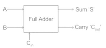
The basic block diagram for a Full Adder is as shown:
A Full adder can be realized using two half adders as shown:
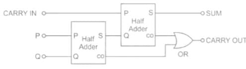
A Full adder can be realized using two half adders as shown:
We, therefore, conclude that a full adder combinational circuit has 3 inputs and 2 outputs.
A full adder can be implemented using 2 XOR, 2 AND, 1 OR as shown in figure:

Important Point
The truth table of a full adder logic is:
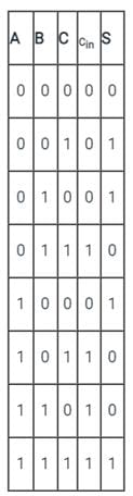
S = A ⊕ B ⊕ C
The Sum output bit of a full adder is given by:
Important Point
The truth table of a full adder logic is:
S = A ⊕ B ⊕ C
The Sum output bit of a full adder is given by:
The carry output bit of a full adder is given by:
X1 = AB + BC + AC
Free Test
FREE
| Start Free Test |
Community Answer
A full adder combinational circuit hasa)3 inputs and 2 outputsb)2 inpu...
Understanding Full Adder Circuits
A full adder is a crucial component in digital electronics, used for binary addition. Let's break down its characteristics:
Inputs of a Full Adder
- A full adder requires three inputs:
- Two inputs represent the bits to be added (let's call them A and B).
- One input is the carry-in (C_in) from a previous less significant bit addition.
Outputs of a Full Adder
- The full adder produces two outputs:
- The sum output (S) results from the addition of the input bits and the carry-in.
- The carry-out (C_out) indicates if there is a carry that needs to be added to the next more significant bit.
Functionality of a Full Adder
- The full adder operates based on the following logic:
- The sum (S) can be calculated as: S = A XOR B XOR C_in.
- The carry-out (C_out) can be calculated as: C_out = (A AND B) OR (C_in AND (A XOR B)).
Conclusion
In summary, a full adder indeed has three inputs and two outputs. It plays a vital role in arithmetic operations within digital circuits, especially in constructing arithmetic logic units (ALUs) and adding circuits. Option 'A' is correct as it accurately reflects the input-output configuration of a full adder.
 | Explore Courses for Electrical Engineering (EE) exam |
Top Courses for Electrical Engineering (EE)View all


Top Courses for Electrical Engineering (EE)
Question Description
A full adder combinational circuit hasa)3 inputs and 2 outputsb)2 inputs and 0 outputsc)1 input and 0 outputd)4 inputs and 1 outputCorrect answer is option 'A'. Can you explain this answer? for Electrical Engineering (EE) 2026 is part of Electrical Engineering (EE) preparation. The Question and answers have been prepared according to the Electrical Engineering (EE) exam syllabus. Information about A full adder combinational circuit hasa)3 inputs and 2 outputsb)2 inputs and 0 outputsc)1 input and 0 outputd)4 inputs and 1 outputCorrect answer is option 'A'. Can you explain this answer? covers all topics & solutions for Electrical Engineering (EE) 2026 Exam. Find important definitions, questions, meanings, examples, exercises and tests below for A full adder combinational circuit hasa)3 inputs and 2 outputsb)2 inputs and 0 outputsc)1 input and 0 outputd)4 inputs and 1 outputCorrect answer is option 'A'. Can you explain this answer?.
A full adder combinational circuit hasa)3 inputs and 2 outputsb)2 inputs and 0 outputsc)1 input and 0 outputd)4 inputs and 1 outputCorrect answer is option 'A'. Can you explain this answer? for Electrical Engineering (EE) 2026 is part of Electrical Engineering (EE) preparation. The Question and answers have been prepared according to the Electrical Engineering (EE) exam syllabus. Information about A full adder combinational circuit hasa)3 inputs and 2 outputsb)2 inputs and 0 outputsc)1 input and 0 outputd)4 inputs and 1 outputCorrect answer is option 'A'. Can you explain this answer? covers all topics & solutions for Electrical Engineering (EE) 2026 Exam. Find important definitions, questions, meanings, examples, exercises and tests below for A full adder combinational circuit hasa)3 inputs and 2 outputsb)2 inputs and 0 outputsc)1 input and 0 outputd)4 inputs and 1 outputCorrect answer is option 'A'. Can you explain this answer?.
Solutions for A full adder combinational circuit hasa)3 inputs and 2 outputsb)2 inputs and 0 outputsc)1 input and 0 outputd)4 inputs and 1 outputCorrect answer is option 'A'. Can you explain this answer? in English & in Hindi are available as part of our courses for Electrical Engineering (EE). Download more important topics, notes, lectures and mock test series for Electrical Engineering (EE) Exam by signing up for free.
Here you can find the meaning of A full adder combinational circuit hasa)3 inputs and 2 outputsb)2 inputs and 0 outputsc)1 input and 0 outputd)4 inputs and 1 outputCorrect answer is option 'A'. Can you explain this answer? defined & explained in the simplest way possible. Besides giving the explanation of A full adder combinational circuit hasa)3 inputs and 2 outputsb)2 inputs and 0 outputsc)1 input and 0 outputd)4 inputs and 1 outputCorrect answer is option 'A'. Can you explain this answer?, a detailed solution for A full adder combinational circuit hasa)3 inputs and 2 outputsb)2 inputs and 0 outputsc)1 input and 0 outputd)4 inputs and 1 outputCorrect answer is option 'A'. Can you explain this answer? has been provided alongside types of A full adder combinational circuit hasa)3 inputs and 2 outputsb)2 inputs and 0 outputsc)1 input and 0 outputd)4 inputs and 1 outputCorrect answer is option 'A'. Can you explain this answer? theory, EduRev gives you an ample number of questions to practice A full adder combinational circuit hasa)3 inputs and 2 outputsb)2 inputs and 0 outputsc)1 input and 0 outputd)4 inputs and 1 outputCorrect answer is option 'A'. Can you explain this answer? tests, examples and also practice Electrical Engineering (EE) tests.
| Explore Courses for Electrical Engineering (EE) exam |
Top Courses for Electrical Engineering (EE)
Explore Courses
Signup for Free!
Signup to see your scores go up within 7 days! Learn & Practice with 1000+ FREE Notes, Videos & Tests.


