


Electrical Engineering (EE) Exam > Electrical Engineering (EE) Questions > A mod–n counter using a synchronous bin... Start Learning for Free
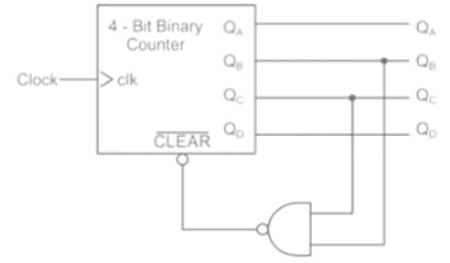
A mod–n counter using a synchronous binary up–counter with synchronous clear input is shown in the figure. The value of n is_________.
(Important - Enter only the numerical value in the answer)
Correct answer is '7'. Can you explain this answer?

Verified Answer
A mod–n counter using a synchronous binary up–counter with...
Concept:
CLR: It is an active low signal. It is activated when CLR = 0 and it resets the FF.
CLR: It is an active high signal. It is activated when CLR = 1 and it Resets the FF.
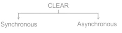
Synchronous: Synchronous clear is synchronized with the clock. It waits for a clock pulse to Reset FF output.
Synchronous: Synchronous clear is synchronized with the clock. It waits for a clock pulse to Reset FF output.
Asynchronous: Asynchronous Clear is not synchronized with the clock. It does not wait for a clock pulse to Reset FF output.
Application:
From given sequential circuit:
CLR = QB ⋅ QC
When both QB & QC equal to 1 then CLR = 0. Otherwise CLR = 1
Now,
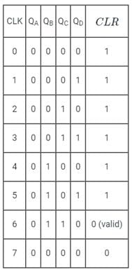
Since it is given that the counter have synchronous clear input, the output of the counter will reset at the 7th clock pulse.
Since it is given that the counter have synchronous clear input, the output of the counter will reset at the 7th clock pulse.
∴ The mod of the counter, n = 7
Most Upvoted Answer
A mod–n counter using a synchronous binary up–counter with...
Concept:
CLR: It is an active low signal. It is activated when CLR = 0 and it resets the FF.
CLR: It is an active high signal. It is activated when CLR = 1 and it Resets the FF.
Synchronous: Synchronous clear is synchronized with the clock. It waits for a clock pulse to Reset FF output.
Synchronous: Synchronous clear is synchronized with the clock. It waits for a clock pulse to Reset FF output.
Asynchronous: Asynchronous Clear is not synchronized with the clock. It does not wait for a clock pulse to Reset FF output.
Application:
From given sequential circuit:
CLR = QB ⋅ QC
When both QB & QC equal to 1 then CLR = 0. Otherwise CLR = 1
Now,
Since it is given that the counter have synchronous clear input, the output of the counter will reset at the 7th clock pulse.
Since it is given that the counter have synchronous clear input, the output of the counter will reset at the 7th clock pulse.
∴ The mod of the counter, n = 7
 | Explore Courses for Electrical Engineering (EE) exam |
Top Courses for Electrical Engineering (EE)View all


Top Courses for Electrical Engineering (EE)
Question Description
A mod–n counter using a synchronous binary up–counter with synchronous clear input is shown in the figure. The value of n is_________. (Important -Enter only the numerical value in the answer)Correct answer is '7'. Can you explain this answer? for Electrical Engineering (EE) 2026 is part of Electrical Engineering (EE) preparation. The Question and answers have been prepared according to the Electrical Engineering (EE) exam syllabus. Information about A mod–n counter using a synchronous binary up–counter with synchronous clear input is shown in the figure. The value of n is_________. (Important -Enter only the numerical value in the answer)Correct answer is '7'. Can you explain this answer? covers all topics & solutions for Electrical Engineering (EE) 2026 Exam. Find important definitions, questions, meanings, examples, exercises and tests below for A mod–n counter using a synchronous binary up–counter with synchronous clear input is shown in the figure. The value of n is_________. (Important -Enter only the numerical value in the answer)Correct answer is '7'. Can you explain this answer?.
A mod–n counter using a synchronous binary up–counter with synchronous clear input is shown in the figure. The value of n is_________. (Important -Enter only the numerical value in the answer)Correct answer is '7'. Can you explain this answer? for Electrical Engineering (EE) 2026 is part of Electrical Engineering (EE) preparation. The Question and answers have been prepared according to the Electrical Engineering (EE) exam syllabus. Information about A mod–n counter using a synchronous binary up–counter with synchronous clear input is shown in the figure. The value of n is_________. (Important -Enter only the numerical value in the answer)Correct answer is '7'. Can you explain this answer? covers all topics & solutions for Electrical Engineering (EE) 2026 Exam. Find important definitions, questions, meanings, examples, exercises and tests below for A mod–n counter using a synchronous binary up–counter with synchronous clear input is shown in the figure. The value of n is_________. (Important -Enter only the numerical value in the answer)Correct answer is '7'. Can you explain this answer?.
Solutions for A mod–n counter using a synchronous binary up–counter with synchronous clear input is shown in the figure. The value of n is_________. (Important -Enter only the numerical value in the answer)Correct answer is '7'. Can you explain this answer? in English & in Hindi are available as part of our courses for Electrical Engineering (EE). Download more important topics, notes, lectures and mock test series for Electrical Engineering (EE) Exam by signing up for free.
Here you can find the meaning of A mod–n counter using a synchronous binary up–counter with synchronous clear input is shown in the figure. The value of n is_________. (Important -Enter only the numerical value in the answer)Correct answer is '7'. Can you explain this answer? defined & explained in the simplest way possible. Besides giving the explanation of A mod–n counter using a synchronous binary up–counter with synchronous clear input is shown in the figure. The value of n is_________. (Important -Enter only the numerical value in the answer)Correct answer is '7'. Can you explain this answer?, a detailed solution for A mod–n counter using a synchronous binary up–counter with synchronous clear input is shown in the figure. The value of n is_________. (Important -Enter only the numerical value in the answer)Correct answer is '7'. Can you explain this answer? has been provided alongside types of A mod–n counter using a synchronous binary up–counter with synchronous clear input is shown in the figure. The value of n is_________. (Important -Enter only the numerical value in the answer)Correct answer is '7'. Can you explain this answer? theory, EduRev gives you an ample number of questions to practice A mod–n counter using a synchronous binary up–counter with synchronous clear input is shown in the figure. The value of n is_________. (Important -Enter only the numerical value in the answer)Correct answer is '7'. Can you explain this answer? tests, examples and also practice Electrical Engineering (EE) tests.
| Explore Courses for Electrical Engineering (EE) exam |
Top Courses for Electrical Engineering (EE)
Explore Courses
Signup for Free!
Signup to see your scores go up within 7 days! Learn & Practice with 1000+ FREE Notes, Videos & Tests.


