Electrical Engineering (EE) Exam > Electrical Engineering (EE) Questions > In case of single line to ground faulta)All s...
Start Learning for Free
In case of single line to ground fault
- a)All sequence networks are connected in parallel
- b)All sequence networks are connected in series
- c)Positive and negative sequence networks are connected in parallel
- d)Zero and negative sequence networks are connected in series
Correct answer is option 'B'. Can you explain this answer?
Most Upvoted Answer
In case of single line to ground faulta)All sequence networks are conn...
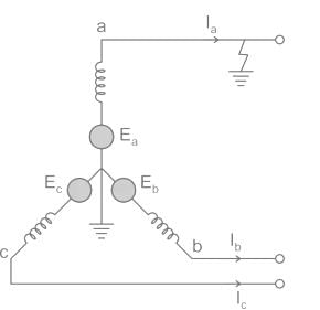
The following circuit shown is a system with a line to ground fault.

Here, Va = 0, Ib = 0, Ic = 0

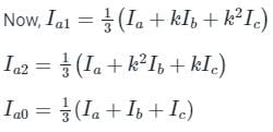
By substituting Ib and Ic values,

Hence in LG faults, all of the three components la0, la1, and la2 are equal.
Va = 0 = Va1 + Va2 + Va0
Now substituting the values of Va0, Va1 and Va2 from the sequence network equation,
Ea – Ia1Z1 – Ia2Z2 – Ia0Z0 = 0
⇒ Ea – Ia1Z1 – Ia1Z2 – Ia1Z0 = 0

From the above equation, it is clear that to simulate an L-G fault all the three sequence networks are required and since the currents are equal in magnitude and phase angle, the three sequence networks must be connected in series. The voltage across each sequence network corresponds to the same sequence component of Va.
The interconnection of the sequence network is shown in the figure.
Free Test
FREE
| Start Free Test |
Community Answer
In case of single line to ground faulta)All sequence networks are conn...
Single Line to Ground Fault
A single line to ground fault is a fault condition in electrical power systems where one of the three power lines comes into contact with the ground or any grounded object. This fault can cause significant damage to the power system if not cleared quickly.
Sequence Networks
In power system analysis, sequence networks are used to model the behavior of the power system during a fault condition. There are three sequence networks: positive sequence network, negative sequence network, and zero sequence network.
- The positive sequence network represents the behavior of the power system under balanced conditions, where all three phases are identical.
- The negative sequence network represents the behavior of the power system when there is an imbalance between the three phases, causing a negative sequence component.
- The zero sequence network represents the behavior of the power system when there is a fault to ground.
Connection of Sequence Networks
When a single line to ground fault occurs, the faulted phase becomes shorted to ground. This fault condition affects the power system, causing imbalances between the three phases.
To analyze the behavior of the power system during a single line to ground fault, the sequence networks are connected in a specific configuration.
- Option A: All sequence networks are connected in parallel. This configuration does not accurately represent the behavior of the power system during a single line to ground fault.
- Option B: All sequence networks are connected in series. This is the correct configuration for analyzing the behavior of the power system during a single line to ground fault. Connecting the sequence networks in series allows for accurate representation of the fault condition and its effects on the power system.
- Option C: Positive and negative sequence networks are connected in parallel. This configuration does not accurately represent the behavior of the power system during a single line to ground fault.
- Option D: Zero and negative sequence networks are connected in series. This configuration does not accurately represent the behavior of the power system during a single line to ground fault.
Conclusion
In conclusion, when analyzing the behavior of a power system during a single line to ground fault, the sequence networks are connected in series. This configuration allows for accurate representation of the fault condition and its effects on the power system.

|
Explore Courses for Electrical Engineering (EE) exam
|

|
Similar Electrical Engineering (EE) Doubts
Question Description
In case of single line to ground faulta)All sequence networks are connected in parallelb)All sequence networks are connected in seriesc)Positive and negative sequence networks are connected in paralleld)Zero and negative sequence networks are connected in seriesCorrect answer is option 'B'. Can you explain this answer? for Electrical Engineering (EE) 2025 is part of Electrical Engineering (EE) preparation. The Question and answers have been prepared according to the Electrical Engineering (EE) exam syllabus. Information about In case of single line to ground faulta)All sequence networks are connected in parallelb)All sequence networks are connected in seriesc)Positive and negative sequence networks are connected in paralleld)Zero and negative sequence networks are connected in seriesCorrect answer is option 'B'. Can you explain this answer? covers all topics & solutions for Electrical Engineering (EE) 2025 Exam. Find important definitions, questions, meanings, examples, exercises and tests below for In case of single line to ground faulta)All sequence networks are connected in parallelb)All sequence networks are connected in seriesc)Positive and negative sequence networks are connected in paralleld)Zero and negative sequence networks are connected in seriesCorrect answer is option 'B'. Can you explain this answer?.
In case of single line to ground faulta)All sequence networks are connected in parallelb)All sequence networks are connected in seriesc)Positive and negative sequence networks are connected in paralleld)Zero and negative sequence networks are connected in seriesCorrect answer is option 'B'. Can you explain this answer? for Electrical Engineering (EE) 2025 is part of Electrical Engineering (EE) preparation. The Question and answers have been prepared according to the Electrical Engineering (EE) exam syllabus. Information about In case of single line to ground faulta)All sequence networks are connected in parallelb)All sequence networks are connected in seriesc)Positive and negative sequence networks are connected in paralleld)Zero and negative sequence networks are connected in seriesCorrect answer is option 'B'. Can you explain this answer? covers all topics & solutions for Electrical Engineering (EE) 2025 Exam. Find important definitions, questions, meanings, examples, exercises and tests below for In case of single line to ground faulta)All sequence networks are connected in parallelb)All sequence networks are connected in seriesc)Positive and negative sequence networks are connected in paralleld)Zero and negative sequence networks are connected in seriesCorrect answer is option 'B'. Can you explain this answer?.
Solutions for In case of single line to ground faulta)All sequence networks are connected in parallelb)All sequence networks are connected in seriesc)Positive and negative sequence networks are connected in paralleld)Zero and negative sequence networks are connected in seriesCorrect answer is option 'B'. Can you explain this answer? in English & in Hindi are available as part of our courses for Electrical Engineering (EE).
Download more important topics, notes, lectures and mock test series for Electrical Engineering (EE) Exam by signing up for free.
Here you can find the meaning of In case of single line to ground faulta)All sequence networks are connected in parallelb)All sequence networks are connected in seriesc)Positive and negative sequence networks are connected in paralleld)Zero and negative sequence networks are connected in seriesCorrect answer is option 'B'. Can you explain this answer? defined & explained in the simplest way possible. Besides giving the explanation of
In case of single line to ground faulta)All sequence networks are connected in parallelb)All sequence networks are connected in seriesc)Positive and negative sequence networks are connected in paralleld)Zero and negative sequence networks are connected in seriesCorrect answer is option 'B'. Can you explain this answer?, a detailed solution for In case of single line to ground faulta)All sequence networks are connected in parallelb)All sequence networks are connected in seriesc)Positive and negative sequence networks are connected in paralleld)Zero and negative sequence networks are connected in seriesCorrect answer is option 'B'. Can you explain this answer? has been provided alongside types of In case of single line to ground faulta)All sequence networks are connected in parallelb)All sequence networks are connected in seriesc)Positive and negative sequence networks are connected in paralleld)Zero and negative sequence networks are connected in seriesCorrect answer is option 'B'. Can you explain this answer? theory, EduRev gives you an
ample number of questions to practice In case of single line to ground faulta)All sequence networks are connected in parallelb)All sequence networks are connected in seriesc)Positive and negative sequence networks are connected in paralleld)Zero and negative sequence networks are connected in seriesCorrect answer is option 'B'. Can you explain this answer? tests, examples and also practice Electrical Engineering (EE) tests.

|
Explore Courses for Electrical Engineering (EE) exam
|

|
Signup to solve all Doubts
Signup to see your scores go up within 7 days! Learn & Practice with 1000+ FREE Notes, Videos & Tests.


