


Electronics and Communication Engineering (ECE) Exam > Electronics and Communication Engineering (ECE) Questions > A circuit with an ideal OPAMP is shown in the...
Start Learning for Free
A circuit with an ideal OPAMP is shown in the figure. A pulse VIN of 20 ms duration is applied to the input. The capacitors are initially uncharged.
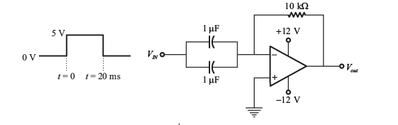
The output voltage Vout of this circuit at t = 0+ (in integer) is ______ V.
Correct answer is '-12'. Can you explain this answer?

Verified Answer
A circuit with an ideal OPAMP is shown in the figure. A pulse VIN of 2...
The given circuit is shown below,
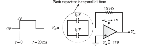
Above figure can be redrawn as
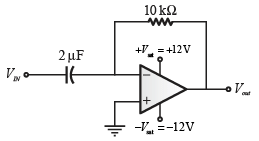
From above circuit it is clear that,
V− =VIN= + 5 V
V+= 0 V
Here, V− ≠V+
It means, voltage at both terminals of op-amp are unequal and fixed so virtual ground concept is not valid here and op-amp work as a comparator.
Thus, V− >V+
So, Vout =−Vsat
Vout =−12 V
Hence, the output voltage Vout of this circuit at t = 0+ is −12 V.
Question_Type: 4
Most Upvoted Answer
A circuit with an ideal OPAMP is shown in the figure. A pulse VIN of 2...
The given circuit is shown below,
Above figure can be redrawn as
From above circuit it is clear that,
V− =VIN= + 5 V
V+= 0 V
Here, V− ≠V+
It means, voltage at both terminals of op-amp are unequal and fixed so virtual ground concept is not valid here and op-amp work as a comparator.
Thus, V− >V+
So, Vout =−Vsat
Vout =−12 V
Hence, the output voltage Vout of this circuit at t = 0+ is −12 V.
Question_Type: 4

|
Explore Courses for Electronics and Communication Engineering (ECE) exam
|
|
Similar Electronics and Communication Engineering (ECE) Doubts


Top Courses for Electronics and Communication Engineering (ECE)View all


Top Courses for Electronics and Communication Engineering (ECE)

Question Description
A circuit with an ideal OPAMP is shown in the figure. A pulse VIN of 20 ms duration is applied to the input. The capacitors are initially uncharged.The output voltage Vout of this circuit at t = 0+ (in integer) is ______ V.Correct answer is '-12'. Can you explain this answer? for Electronics and Communication Engineering (ECE) 2025 is part of Electronics and Communication Engineering (ECE) preparation. The Question and answers have been prepared according to the Electronics and Communication Engineering (ECE) exam syllabus. Information about A circuit with an ideal OPAMP is shown in the figure. A pulse VIN of 20 ms duration is applied to the input. The capacitors are initially uncharged.The output voltage Vout of this circuit at t = 0+ (in integer) is ______ V.Correct answer is '-12'. Can you explain this answer? covers all topics & solutions for Electronics and Communication Engineering (ECE) 2025 Exam. Find important definitions, questions, meanings, examples, exercises and tests below for A circuit with an ideal OPAMP is shown in the figure. A pulse VIN of 20 ms duration is applied to the input. The capacitors are initially uncharged.The output voltage Vout of this circuit at t = 0+ (in integer) is ______ V.Correct answer is '-12'. Can you explain this answer?.
A circuit with an ideal OPAMP is shown in the figure. A pulse VIN of 20 ms duration is applied to the input. The capacitors are initially uncharged.The output voltage Vout of this circuit at t = 0+ (in integer) is ______ V.Correct answer is '-12'. Can you explain this answer? for Electronics and Communication Engineering (ECE) 2025 is part of Electronics and Communication Engineering (ECE) preparation. The Question and answers have been prepared according to the Electronics and Communication Engineering (ECE) exam syllabus. Information about A circuit with an ideal OPAMP is shown in the figure. A pulse VIN of 20 ms duration is applied to the input. The capacitors are initially uncharged.The output voltage Vout of this circuit at t = 0+ (in integer) is ______ V.Correct answer is '-12'. Can you explain this answer? covers all topics & solutions for Electronics and Communication Engineering (ECE) 2025 Exam. Find important definitions, questions, meanings, examples, exercises and tests below for A circuit with an ideal OPAMP is shown in the figure. A pulse VIN of 20 ms duration is applied to the input. The capacitors are initially uncharged.The output voltage Vout of this circuit at t = 0+ (in integer) is ______ V.Correct answer is '-12'. Can you explain this answer?.
Solutions for A circuit with an ideal OPAMP is shown in the figure. A pulse VIN of 20 ms duration is applied to the input. The capacitors are initially uncharged.The output voltage Vout of this circuit at t = 0+ (in integer) is ______ V.Correct answer is '-12'. Can you explain this answer? in English & in Hindi are available as part of our courses for Electronics and Communication Engineering (ECE).
Download more important topics, notes, lectures and mock test series for Electronics and Communication Engineering (ECE) Exam by signing up for free.
Here you can find the meaning of A circuit with an ideal OPAMP is shown in the figure. A pulse VIN of 20 ms duration is applied to the input. The capacitors are initially uncharged.The output voltage Vout of this circuit at t = 0+ (in integer) is ______ V.Correct answer is '-12'. Can you explain this answer? defined & explained in the simplest way possible. Besides giving the explanation of
A circuit with an ideal OPAMP is shown in the figure. A pulse VIN of 20 ms duration is applied to the input. The capacitors are initially uncharged.The output voltage Vout of this circuit at t = 0+ (in integer) is ______ V.Correct answer is '-12'. Can you explain this answer?, a detailed solution for A circuit with an ideal OPAMP is shown in the figure. A pulse VIN of 20 ms duration is applied to the input. The capacitors are initially uncharged.The output voltage Vout of this circuit at t = 0+ (in integer) is ______ V.Correct answer is '-12'. Can you explain this answer? has been provided alongside types of A circuit with an ideal OPAMP is shown in the figure. A pulse VIN of 20 ms duration is applied to the input. The capacitors are initially uncharged.The output voltage Vout of this circuit at t = 0+ (in integer) is ______ V.Correct answer is '-12'. Can you explain this answer? theory, EduRev gives you an
ample number of questions to practice A circuit with an ideal OPAMP is shown in the figure. A pulse VIN of 20 ms duration is applied to the input. The capacitors are initially uncharged.The output voltage Vout of this circuit at t = 0+ (in integer) is ______ V.Correct answer is '-12'. Can you explain this answer? tests, examples and also practice Electronics and Communication Engineering (ECE) tests.
|
|
Explore Courses for Electronics and Communication Engineering (ECE) exam
|
|

Signup to solve all Doubts
Signup to see your scores go up within 7 days! Learn & Practice with 1000+ FREE Notes, Videos & Tests.


x
![]()
For Your Perfect Score in Electronics and Communication Engineering (ECE)
The Best you need at One Place
|
© EduRev
|
Education Revolution
|


|


Signup to see your scores
go up within 7 days!
Access 1000+ FREE Docs, Videos and Tests
Takes less than 10 seconds to signup