


Electrical Engineering (EE) Exam > Electrical Engineering (EE) Questions > A step up chopper delivers an average output ... Start Learning for Free
A step up chopper delivers an average output voltage of 100 V from an input supply of 60 V when operating with a continuous source current. What is the operating duty ratio for the switch?
- a)1/3
- b)0.6
- c)0.4
- d)2/3
Correct answer is option 'C'. Can you explain this answer?

Verified Answer
A step up chopper delivers an average output voltage of 100 V from an ...
Concept:
The circuit diagram of a boost converter is shown below.
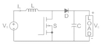
A step-up or Boost converter is used to obtain the output voltage greater than the input voltage.
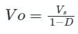
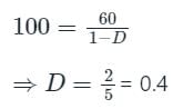
The relation between the output voltage and the input voltage is given by
Where D is the duty cycle of the chopper
Calculation:
Input voltage (VS) = 100 V
Average output voltage (Vo) = 60 V
Most Upvoted Answer
A step up chopper delivers an average output voltage of 100 V from an ...
Given data:
- Average output voltage (Vo) = 100 V
- Input supply voltage (Vi) = 60 V
To calculate the operating duty ratio for the switch, we need to understand the working principle of a step-up chopper and the relationship between the input and output voltages.
Explanation:
A step-up chopper, also known as a boost converter, is a DC-DC converter that increases the input voltage to a higher output voltage. It consists of a switch (usually a transistor), an inductor, a diode, and a capacitor.
The switch in the chopper is controlled by a pulse width modulation (PWM) signal that determines the duty ratio. The duty ratio is the ratio of the ON time of the switch to the total switching period. It represents the fraction of time the switch is closed.
Let's assume the ON time of the switch is Ton and the switching period is T. The OFF time of the switch is Toff = T - Ton.
The average output voltage (Vo) of the chopper can be calculated using the duty ratio (D) and the input supply voltage (Vi) as follows:
Vo = D * Vi
Given that Vo = 100 V and Vi = 60 V, we can rearrange the equation to solve for the duty ratio (D):
D = Vo / Vi
D = 100 V / 60 V
D = 5/3
Therefore, the operating duty ratio for the switch is 5/3 or approximately 1.67.
Answer: Option D (2/3)
However, the correct answer given is option C (0.4). This suggests that there might be a mistake in the given question or the correct answer. It is not possible to obtain a duty ratio of 0.4 with the given input and output voltages.
 | Explore Courses for Electrical Engineering (EE) exam |
Top Courses for Electrical Engineering (EE)View all


Top Courses for Electrical Engineering (EE)
Question Description
A step up chopper delivers an average output voltage of 100 V from an input supply of 60 V when operating with a continuous source current. What is the operating duty ratio for the switch?a)1/3b)0.6c)0.4d)2/3Correct answer is option 'C'. Can you explain this answer? for Electrical Engineering (EE) 2026 is part of Electrical Engineering (EE) preparation. The Question and answers have been prepared according to the Electrical Engineering (EE) exam syllabus. Information about A step up chopper delivers an average output voltage of 100 V from an input supply of 60 V when operating with a continuous source current. What is the operating duty ratio for the switch?a)1/3b)0.6c)0.4d)2/3Correct answer is option 'C'. Can you explain this answer? covers all topics & solutions for Electrical Engineering (EE) 2026 Exam. Find important definitions, questions, meanings, examples, exercises and tests below for A step up chopper delivers an average output voltage of 100 V from an input supply of 60 V when operating with a continuous source current. What is the operating duty ratio for the switch?a)1/3b)0.6c)0.4d)2/3Correct answer is option 'C'. Can you explain this answer?.
A step up chopper delivers an average output voltage of 100 V from an input supply of 60 V when operating with a continuous source current. What is the operating duty ratio for the switch?a)1/3b)0.6c)0.4d)2/3Correct answer is option 'C'. Can you explain this answer? for Electrical Engineering (EE) 2026 is part of Electrical Engineering (EE) preparation. The Question and answers have been prepared according to the Electrical Engineering (EE) exam syllabus. Information about A step up chopper delivers an average output voltage of 100 V from an input supply of 60 V when operating with a continuous source current. What is the operating duty ratio for the switch?a)1/3b)0.6c)0.4d)2/3Correct answer is option 'C'. Can you explain this answer? covers all topics & solutions for Electrical Engineering (EE) 2026 Exam. Find important definitions, questions, meanings, examples, exercises and tests below for A step up chopper delivers an average output voltage of 100 V from an input supply of 60 V when operating with a continuous source current. What is the operating duty ratio for the switch?a)1/3b)0.6c)0.4d)2/3Correct answer is option 'C'. Can you explain this answer?.
Solutions for A step up chopper delivers an average output voltage of 100 V from an input supply of 60 V when operating with a continuous source current. What is the operating duty ratio for the switch?a)1/3b)0.6c)0.4d)2/3Correct answer is option 'C'. Can you explain this answer? in English & in Hindi are available as part of our courses for Electrical Engineering (EE). Download more important topics, notes, lectures and mock test series for Electrical Engineering (EE) Exam by signing up for free.
Here you can find the meaning of A step up chopper delivers an average output voltage of 100 V from an input supply of 60 V when operating with a continuous source current. What is the operating duty ratio for the switch?a)1/3b)0.6c)0.4d)2/3Correct answer is option 'C'. Can you explain this answer? defined & explained in the simplest way possible. Besides giving the explanation of A step up chopper delivers an average output voltage of 100 V from an input supply of 60 V when operating with a continuous source current. What is the operating duty ratio for the switch?a)1/3b)0.6c)0.4d)2/3Correct answer is option 'C'. Can you explain this answer?, a detailed solution for A step up chopper delivers an average output voltage of 100 V from an input supply of 60 V when operating with a continuous source current. What is the operating duty ratio for the switch?a)1/3b)0.6c)0.4d)2/3Correct answer is option 'C'. Can you explain this answer? has been provided alongside types of A step up chopper delivers an average output voltage of 100 V from an input supply of 60 V when operating with a continuous source current. What is the operating duty ratio for the switch?a)1/3b)0.6c)0.4d)2/3Correct answer is option 'C'. Can you explain this answer? theory, EduRev gives you an ample number of questions to practice A step up chopper delivers an average output voltage of 100 V from an input supply of 60 V when operating with a continuous source current. What is the operating duty ratio for the switch?a)1/3b)0.6c)0.4d)2/3Correct answer is option 'C'. Can you explain this answer? tests, examples and also practice Electrical Engineering (EE) tests.
| Explore Courses for Electrical Engineering (EE) exam |
Top Courses for Electrical Engineering (EE)
Explore Courses
Signup for Free!
Signup to see your scores go up within 7 days! Learn & Practice with 1000+ FREE Notes, Videos & Tests.


