Class 7 Exam > Class 7 Questions > Draw a well labelled diagram of electric bell...
Start Learning for Free
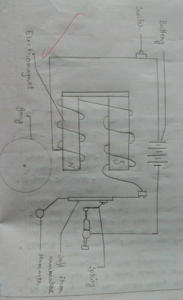
Draw a well labelled diagram of electric bell?
Most Upvoted Answer
Draw a well labelled diagram of electric bell?

Community Answer
Draw a well labelled diagram of electric bell?
Introduction:
An electric bell is a device that produces sound when an electric current is passed through it. It is commonly used in schools, offices, and homes as an alerting device.
Diagram:
The diagram of an electric bell includes the following parts:
1. Electromagnet
2. Armature
3. Spring
4. Hammer
5. Gong or bell
Working:
When an electric current passes through the coil of the electromagnet, it creates a magnetic field. This magnetic field pulls the armature towards the electromagnet, causing it to strike the hammer. The hammer then hits the gong or bell, creating a ringing sound.
Components:
Each of the components of an electric bell has its own function in the working of the bell.
1. Electromagnet: The electromagnet is made up of a coil of wire wrapped around a core of iron. When an electric current is passed through the coil, it creates a magnetic field.
2. Armature: The armature is a piece of iron that is attracted to the magnetic field created by the electromagnet. When the magnetic field is strong enough, the armature is pulled towards the electromagnet.
3. Spring: The spring is attached to the armature and provides a restoring force to pull the armature back to its original position when the electric current is turned off.
4. Hammer: The hammer is attached to the armature and strikes the gong or bell to produce sound.
5. Gong or bell: The gong or bell is the component of the electric bell that produces the sound.
Conclusion:
In conclusion, the electric bell is an important device used for alerting purposes in schools, offices, and homes. It works by using an electromagnet to attract an armature which in turn hits a hammer that strikes a gong or bell to produce sound.

|
Explore Courses for Class 7 exam
|

|
Similar Class 7 Doubts
Draw a well labelled diagram of electric bell?
Question Description
Draw a well labelled diagram of electric bell? for Class 7 2025 is part of Class 7 preparation. The Question and answers have been prepared according to the Class 7 exam syllabus. Information about Draw a well labelled diagram of electric bell? covers all topics & solutions for Class 7 2025 Exam. Find important definitions, questions, meanings, examples, exercises and tests below for Draw a well labelled diagram of electric bell?.
Draw a well labelled diagram of electric bell? for Class 7 2025 is part of Class 7 preparation. The Question and answers have been prepared according to the Class 7 exam syllabus. Information about Draw a well labelled diagram of electric bell? covers all topics & solutions for Class 7 2025 Exam. Find important definitions, questions, meanings, examples, exercises and tests below for Draw a well labelled diagram of electric bell?.
Solutions for Draw a well labelled diagram of electric bell? in English & in Hindi are available as part of our courses for Class 7.
Download more important topics, notes, lectures and mock test series for Class 7 Exam by signing up for free.
Here you can find the meaning of Draw a well labelled diagram of electric bell? defined & explained in the simplest way possible. Besides giving the explanation of
Draw a well labelled diagram of electric bell?, a detailed solution for Draw a well labelled diagram of electric bell? has been provided alongside types of Draw a well labelled diagram of electric bell? theory, EduRev gives you an
ample number of questions to practice Draw a well labelled diagram of electric bell? tests, examples and also practice Class 7 tests.

|
Explore Courses for Class 7 exam
|

|
Signup for Free!
Signup to see your scores go up within 7 days! Learn & Practice with 1000+ FREE Notes, Videos & Tests.


