Bends & Fittings | Fluid Mechanics for Mechanical Engineering PDF Download
| Table of contents |

|
| Force exerted by a flowing fluid on Pipe − Bend |

|
| Moment of Momentum Equation |

|
| Free Liquid Jets |

|
| Orifice Meter or Orifice Plate |

|
| Pitot Tube |

|
| Flow Through Large Orifices |

|
| Solved Numericals |

|
Force exerted by a flowing fluid on Pipe − Bend
The impulse momentum equation is used to determine the resultant force exerted by a flowing fluid on a pipe bend. Consider two sections (1) and (2) as shown in fig.
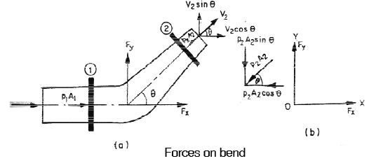 Let, V1 = Velocity of flow at section (1)
p1 = pressure intensity at section (1)
A1 = area of cross section of pipe at section (1) and
V2, p2.,A2 = corresponding values of velocity, pressure and area at section (2)
Let Fx and Fy be the components of the forces exerted by the flowing fluid on the bend in x and y direction respectively. Then
Fx = ρ Q (V1 − V2 cosθ ) + p1 A1 − p1 A2 cosθ
Fy = ρ Q (−V2 sin θ) − p2 A2 sin θ
The resultant force (FR) acting on the bend =  And the angle made by the resultant force with horizontal direction is given by
tanθ = Fy / Fx
Moment of Momentum Equation
The moment of momentum equation is derived from the principle of moment of momentum, which states that the resulting torque acting on a rotating fluid is equal to the rate of change of moment of momentum. The moment of momentum equation can be expressed as follows:Given:
- V1 = Velocity of fluid at section 1
- r1 = Radius of curvature at section 1
- V2 = Velocity of fluid at section 2
- r2 = Radius of curvature at section 2
- Q = Rate of flow of fluid
- ρ = Density of fluid
The resultant torque T is given by:
This equation is known as the moment of momentum equation. It is applied in the following scenarios:
Analyzing Flow Problems in Turbines and Centrifugal Pumps: The moment of momentum equation is essential for understanding the forces and torques involved in the operation of turbines and centrifugal pumps. It helps in designing and optimizing these devices to achieve efficient energy conversion and fluid handling.
Finding Torque Exerted by Water on a Sprinkler: The equation is also used to determine the torque exerted by water on a sprinkler, which is crucial for the design and performance evaluation of irrigation systems and similar applications.
By applying the moment of momentum equation, engineers can predict and control the behavior of rotating fluid systems, ensuring their effective and reliable operation.
Free Liquid Jets
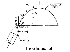
A free liquid jet is defined as the jet of water that emerges from a nozzle into the atmosphere. The path traveled by the free jet is parabolic.Consider a jet of water coming from a nozzle at point A, as shown in the figure below. Let the jet at point A make an angle θ with the horizontal direction. If U is the velocity of the jet of water, then the horizontal and vertical components of this velocity at point A are Ucosθ and Usinθ, respectively.
Now, consider another point P(x, y) on the centerline of the jet. The coordinates of point P relative to point A are x and y.
Equation of motion 
Maximum height attained by the jet 
Time of flight 
Time to reach highest point 
Horizontal range of the jet 
Maximum horizontal range
Hydraulic Coefficients
The hydraulic Coefficients are:- Coefficient of velocity, Cv
- Coefficient of contraction, Cc
- Coefficient of discharge, Cd
1. Coefficient of velocity (Cv): It is defined as the ratio between the actual velocity of jet of liquid at vena − contracta and the theoretical velocity of jet. It is denoted by Cv and mathematically Cv is given as:
The value of Cv varies from 0.95 to 0.99 for different orifices, depending upon the shape, size of the orifice and on the head under which the flow takes place. Cv is generally taken as 0.98 for sharp edged orifices.
2. Coefficient of Contraction (Cc): It is defined as the ratio of the area of the jet at vena − contracta to the area of orifice. It is denoted by Cc . 
The value of Cc varies form 0.61 to 0.69 depending on shape and size of the orifice and head of liquid under which flow takes place. In general, the value of Cc may be taken as 0.64,
3. Coefficient of discharge (Cd): It is defined as the ratio of actual discharge from an orifice to the theoretical discharge from the orifice. It is denoted by Cd

Also Cd = Cv × Cc
The value of Cd varies from 0.61 to 0.65. For general purpose, the value of Cd is taken as 0.62.
Venturimeter
A Venturimeter is a device used for measuring the rate of flow of a fluid through a pipe. It operates based on the principles of Bernoulli's equation and consists of three main parts:Converging Section: This is the inlet section where the fluid enters the Venturimeter. The diameter of the pipe decreases in this section, causing the velocity of the fluid to increase and the pressure to decrease due to the conservation of energy as described by Bernoulli's equation.
Throat: The throat is the narrowest part of the Venturimeter. Here, the velocity of the fluid reaches its maximum, and the pressure is at its minimum. The significant pressure drop at the throat is utilized to measure the flow rate.
Diverging Section: After the throat, the pipe diameter increases again in the diverging section. This causes the velocity of the fluid to decrease and the pressure to increase as it exits the Venturimeter.
Expression for Rate of Flow through Venturimeter
Consider a venturimeter fitted in a horizontal pipe through which a fluid is flowing (say water) as shown in fig.
Let d1 = diameter at inlet or at section (1)
p1 = pressure at section (1)
V1 = Velocity of fluid at section (1)
A1 = area of section (1) = 
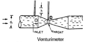
And d2, p2, V2, a2, are corresponding values at section (2).
Discharge, 
Where  = Difference of pressure heads at sections (1) and (2).
Above equation gives the discharge under ideal conditions and is called, theoretical discharge. Actual discharge will be less than theoretical discharge.
Where Cd is the coefficient of discharge.
Value of ‘h’ givenby differential U −tube manometer.
Case I: Let the differential manometer contains a liquid which is heavier than the liquid flowing through the pipe.
Let
Sh = sp.gr. of the heavier liquid
So = sp.gr. of the liquid flowing through pipe
x = difference of the heavier liquid column in U− tube
Then 
Case II: If the differential manometer contains a liquid which is lighter than the liquid flowing through the pipe, the value of h is given by  Where Sl = sp. gr. of lighter liquid in U − tube.
Orifice Meter or Orifice Plate
It is a cheaper device as compared to venturimeter. It consists of a flat circular plate which has circular shape edged hole called orifice, which is concentric with the pipe. The orifice diameter is kept generally 0.5 times the diameter of the pipe, through it may vary from 0.4 to 0.8 times the pipe diameter.A differential manometer is connected at section (1), which is at a distance of about 1.5 time to 2.0 times the pipe diameter upstream from the orifice plate, and at section (2), which is at a distance about half the diameter of the orifice on the down stream side from the orifice plate.
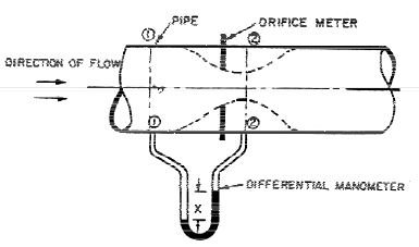 Orifice meter
Let p1 = pressure at section (1),
V1 = velocity at section (1),
a1 = area of pipe at section (1),
p2, V2, a2, are corresponding values at section (2)
Discharge, 
Section (2) at vena − contracts and a2 represents the area of the vena − contract. If ao is the area of orifice then, 
Where Cc = coefficient of contraction
The coefficient of discharge for orifice meter is much smaller than that for a venturimeter.
Pitot Tube
A Pitot tube is a device used for measuring the velocity of fluid flow at any point in a pipe or channel. It operates on the principle that if the velocity of flow at a point becomes zero (stagnation point), the pressure at that point increases due to the conversion of kinetic energy into pressure energy.Components and Operation
In its simplest form, a Pitot tube consists of a glass tube bent at right angles. The lower end of the tube, which is bent through 90°, is directed upstream into the flow. The arrangement is shown in the figure below: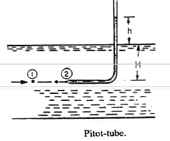
The velocity at any point in flow is given by Where Cv = coefficient of velocity
h = Height of liquid in the pitot tube above water surface.
Experimental Determination of Hydraulic Coefficients:
1. Determination o f Cd: The water is allowed to flow through an orifice fitted to a tank under a constant head, H, as shown in Fig. The water is collected in a measuring tank for a known time, t.The height of water in the measuring tank is noted down.
Then actual discharge through orifice,

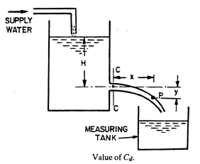 And theoretical discharge = area of orifice × v
where V = √2GH = velocity of free fall from height H

2. Determination of coefficient of Velocity(Cv): Let C − C represents the vena − contracta of a jet of water coming out from an orifice under constant head H as shown in fig. (above). Consider a liquid particle which is at vena − contracta at any time and takes the position at P along the jet in time ‘t’.
Let x = horizontal distance travelled by the particles in time ‘t’
y = vertical distance between P and C − C
V = actual velocity of jet at vena contracata
Then
Flow Through Large Orifices
If the head of liquid is less than 5 times the depth of the orifice, the orifice is called large orifice. In case of small orifice, the velocity in the centre cross − section of the jet is considered to be constant and discharge can be calculated by Q = Cd × a × √2gh . But, in case of a large orifice, the velocity is not constant over the entire cross section of the jet and hence Q cannot be calculated by above formula.1. Discharge Through Large Rectangular Orifice: Consider a large rectangular orifice in one side of the tank discharging freely into atmosphere under a constant head, H as shown in fig. 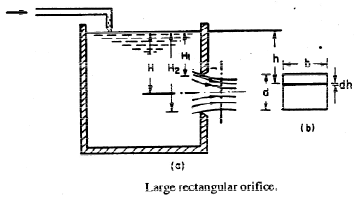
Let H1 = height of liquid above top edge of orifice
H2 = height of liquid above bottom edge of orifice
b = breadth of orifice
d = depth of orifice = H2 −H1
Cd = coefficient of discharge
Then discharge,
2. Discharge Through Fully Submerged Orifice: Fully submerged orifice is one which has its whole of the outlet side sub merged under liquid so that it discharges a jet of liquid into the liquid of the same kind. It is also called totally drowned orifice. Consider two points (1) and (2), point (1) being in the reservoir on the upstream side of the orifice and point (2) being at the vena contracta as shown in fig. 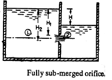 Let H1 = Height of water above the top of the orifice on the upstream side.
H2 = Height of water above the bottom of the orifice
H = Difference in water level
b = width of orifice
Cd = Coefficient of discharge
Discharge through orifice, Q = Cd × b (H2 − H1) × √2gH
3. Discharge Through Partially Submerged Orifice: Partially submerged orifice is one which has its outlet side partially submerged under liquid as shown in fig. It is also known as partially downed orifice. 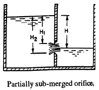 Discharge ; Q =
4. Time of Emptying a Cylindrical Tank Through an Orifice at its Bottom: Consider a tank containing some liquid upto a height H1. Let an orifice is fitted at the bottom of the tank. It is required to find the time for the liquid surface to fall form the height H1 to a height H2.
Let A = Area of the tank
a = Area of the orifice
H1 = Initial height of the liquid
H2 = Final height of the liquid
T = Time in seconds for the liquid to fall from height H1 to H2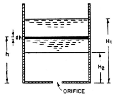
Hence, 
For emptying the tank completely; H2 = 0 and
5. Time of Emptying a Hemispherical Tank: Consider a hemispherical tank of radius R fitted with an orifice of area ‘a’ at its bottom as shown in Fig. The tank contains some liquid whose initial height is H1 and in time T, the height of liquid falls to height H2.
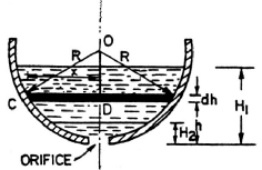 hemispherical tank
Here, 
For completely emptying the tank, H2 = 0 and hence
6. Time of Emptying a Circular Horizontal Tank: Consider a circular horizontal tank of length L and radius R, containing liquid upto a height of H1. Let an orifice of area ‘a’ is fitted at the bottom of the tank. Let T is the time required to bring the liquid level from H1 to H2. 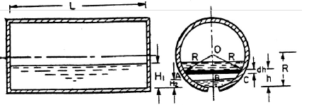
Then, 
For completely emptying the tank, H2 = 0 and hence
Solved Numericals
Q1. The pressure drop of water in a pipe is measured by a manometer using a liquid of density 2000 kg/m3. The difference in height of the liquid in the limbs is 10 cm. Then, the pressure drop is :
Ans: Apply Bernoulli’s equation between 1 and 2;
After a bit of simplification,

The above expression is representing the piezometric head difference.
For the same reference level,
Pressure head is given by: Here, h represents the height difference between the liquid column in two limbs of the manometer.
Given:
ρm = 2000 kg/m3
⇒ Sm = 2, S = 1, h = 10 cm = 0.1 m
We know that

ΔP = 1000 × 9.81 × 0.1 × (2 - 1)
ΔP = 981 N/m2
Q2. A head loss in a sudden expansion from 6 cm diameter pipe to 12 cm diameter pipe in terms of velocity v1 in the smaller diameter pipe is
Ans: Loss of head due expansion, Given:
D1 = 6 cm, D2 = 12 cm
We know,
A1V1 = A2V2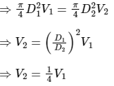
Loss of head due expansion,
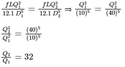
Q3. Two pipe lines of equal length and diameters of 10 cm and 40 cm are connected in parallel between two reservoirs. If friction factor f is same for both the pipes, the ratio of the discharges in the larger to the smaller pipe is
Ans: Flow-through Pipes: In flow-through pipe different type of losses takes place.
Major losses are due to viscous (friction) resistance through the wall, and head loss due to friction is given by Darcy's Weichback equation: where, f = friction factor, L = length of pipe, D = diameter of the pipe, Q = pipe flow
Minor losses these losses are due to change in momentum of the fluid due to the sudden expansion or contraction, change in the shape of the pipe.
Compound Pipes: Types of pipe connection are:
In Series Connection of pipe discharge is same and losses are different in each pipe.
- Q1 = Q2 = Q3 = ................ = Q
- Equivalent head hf = hf1 + hf2 + hf2 ....
In Parallel Connection of pipe discharge is different and losses are same in each pipe. - Q = Q1 + Q2 + Q3 ..... + Q
- Equivalent head hf = hf1 = hf2 = hf2 ......
Calculation:
Given:
D1 = 10 cm, D2 = 40 cm , same length L1 = L2 = L, same friction factor f1 = f2 = f
In parallel Connection Head loss in pipe are equal:
hf1 = hf2
|
56 videos|146 docs|75 tests
|
FAQs on Bends & Fittings - Fluid Mechanics for Mechanical Engineering
| 1. What is the force exerted by a flowing fluid on a pipe bend? |  |
| 2. How is the flow rate of a free liquid jet measured? |  |
| 3. What is the purpose of an orifice meter or orifice plate in fluid flow measurement? |  |
| 4. How does the flow through large orifices differ from flow through small orifices? |  |
| 5. How do bends and fittings affect the flow of a fluid in a pipeline? |  |


