Basics & Air Standard Cycles | Thermodynamics - Mechanical Engineering PDF Download
Overview
- A heat engine is a device which transforms the chemical energy of a fuel into thermal energy and uses this energy to produce mechanical work.
Materials for Construction of I.C Engine parts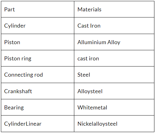
Components of IC Engine
Various Strokes of 4-stroke Engine 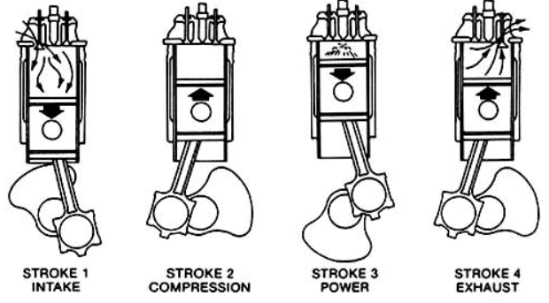
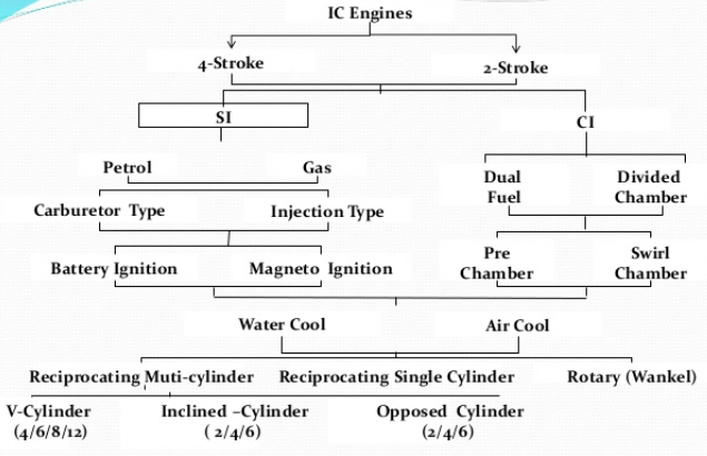
Two Stroke Engines
- In two stroke engine, two strokes of piston or one revolution of crankshaft completes the cycle.
- Inlet of mixture or fuel and exhaust of combustion products starts one by one (first exhaust port is opened then inlet port) in the expansion stroke and completes one by one (first inlet port is closed then exhaust port) in compression stroke. The piston head has deflector to avoid exhaust of fresh mixture from exhaust port.
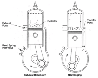
Scavenging process
- The process of cleaning the cylinder after the expansion stroke is scavenging. Here the fresh fuel or mixture pushes the exhaust to exhaust port.
Type of scavenging process
- Uniflow system has highest scavenging efficiency
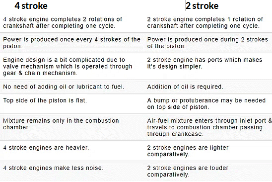
Comparison of four stroke and two-stroke engine
Comparison of engines working on Otto and Diesel Cycle
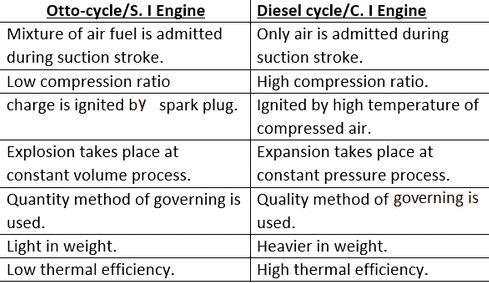 Note: High speed diesel engine follows dual cycle.
Performance Parameters of I.C. Engine
- The energy of the fuel that is converted to power is called the indicated power (i.p.)
- The energy of the fuel that is converted to passes through the connecting rod to the crank shaft. In this transmission there are energy losses, due to friction, pumping etc. The sum of all there losses converted to power is termed as friction power (f.p)
- Brake power (b.p.) = Indicated power (i.p.) – Friction power (f.p.)
- Indicated Thermal Efficiency (hit )

where,
mf = mass of fuel /sec
QLHV = Lower calorific value of fuel
I.P. = Indicated power
- Brake thermal efficiency (hb.t )
- Mechanical efficiency (hm)
- Volumetric efficiency (ηV)
Volume of air actually inducted
- Brake Specific Fuel Consumption (bsfc)
mf = mass of fuel/hour (kg/h)
B.P. = brake power (kW)
- Indicated Specific fuel consumption (isfc)
- Air fuel ratio (A/F ratio)
- Stoichiometric Air fuel ratio
- Heating value : when the product of combustion are cooled to 25ºC, practically all the water resulting from the combustion process will be condensed. The heating value so obtained is higher heating value. When water vapour are not condensed then the heating value is lower calorific value.
- Lower calorific value of fule (QLHV)
QLHV = QHHV - mw ´ LW
QHHV = Higher calorific value
mW = mass of water vapour
Lw = Latent heat of Condensation of water vapour
- i.p =
(for two stroke engine) - i.p =
(for four stroke engine) - b.p =
P = π
L = Stroke of the piston
A = Cross sectional area of the cylinder
N = r.p.m. of the crank shaft
n = number of cylinders
T = Torque on the crank shaft
Mean Effective Pressure
Pmean (V1 – V2) = Workdone
Pm(mean effective pressure) is the constant hypothetical pressure acting during the cycle which produces the same work output as the actual cycle. Increasing the compression ratio will increase the Pmean which increases the efficiency of the cycle.
Assumption of Ideal Air Standard Cycle
- The working medium is assumed to be a perfect gas and follows the relation PV = mRT.
- There is no change in the mass of the working medium.
- All the processes in the cycle are assumed to be reversible.
- There is no heat loss from the system to the surroundings.
- The working medium has constant specific heats throughout the cycle.
- Physical constant Cp, Cv, g and m of the working medium are the same as those of air at standard atmospheric conditions
Otto Cycle
The Otto cycle is the ideal cycle for spark-ignition (SI) or gasoline engines.
| Process | Description |
| 1-2 | Isentropic (Reversible Adiabatic) Compression |
| 2-3 | Constant Volume (Isochoric) Heat Addition |
| 3-4 | Isentropic (Reversible Adiabatic) Expansion |
| 4-1 | Constant Volume (Isochoric) Heat Rejection |
Diesel Cycle
The Diesel cycle is the ideal cycle for compression-ignition (CI) or diesel engines.
| Process | Description |
| 1-2 | Isentropic (Reversible Adiabatic) Compression |
| 2-3 | Constant Pressure (Isobaric) Heat Addition |
| 3-4 | Isentropic (Reversible Adiabatic) Expansion |
| 4-1 | Constant Volume (Isochoric) Heat Rejection |
- Compression ratio (r) =
- Cut off ratio(rc) =

- Expansion ratio (re)
rc * re = r
- Thermal efficiency(ηdiesel)

- ηDiesel is the maximum thermal efficiency of a Diesel cycle
- α is the cut-off ratio V3/V2 (i.e. the ratio of volumes at the end and start of the combustion phase)
- CR is the compression ratio
- κ = cp/cv = 1.4
- As the compression ratio increase or cut- off ratio (rc) decreases, thermal efficiency hth of the diesel cycle increases
Dual Cycle
- Dual cycle is the combination of both diesel cycle and otto cycle. The efficiency of dual cycle is more than diesel cycle but less than otto cycle. In heat addition process first there will be constant volume for some time and then constant pressure till the end of heat addition process.
- Process 1-2: Isentropic compression
- Process 2-3: Addition of heat at constant volume.
- Process 3-4: Addition of heat at constant pressure.
- Process 4-5: Isentropic expansion.
- Process 5-1: Rejection of heat at constant volume.
- Compression ratio (r) =
- Pressure ratio (rp) =
- rc = V4/V3
- Thermal efficiency =

- When compression ratio increases or cut- off ratio 'r' decreases or pressure ratio
(rp) increases efficiency 'ηdual' of the dual cycle increases.
(a) If r =1, Dual cycle becomes Otto cycle
(b) If rp =1, Dual cycle becomes Diesel cycle
Comparison Among Otto, Diesel & Dual Cycles
The important variable factors which are used as the basis for comparison of the cycle are compression ratio, peak pressure, heat addition, heat rejection and the net work. In order to compare the performance of the Otto. Diesel and Dual combustion cycles. some of the variable factors must be fixed. In this section, a comparison of these three cycles is made for the same comparison ratio, same heat addition, constant maximum pressure and temperature, same heat rejection and net work output. This analysis will show which cycles is more efficient for a given set of operating conditions.Case-1 Same Compression Ratio and Heat Addition
- The Otto cycle 1-2-3-4-1, the Diesel cycle 1-2-3'-4'-1 and the Dual cycle 1-2- 2"3"4'-1 are shown in p-V and T-S diagram in figure (a) and (b) respectively for the same compression ratio and heat input.
From the T-S diagram, it can be seen that Area 5-2-3-6=Area 5-2-3'-6' = Area 5-2-2"-6" as this area represents the heat input which is the same for all cycles. All the cycles start from the same initial state point 1 and the air is compressed from state 1 to 2 as the compression ratio is same. It is seen from the T-S diagram for the same heat input, the heat rejection in Otto cycle (are 5-1-4-6) is minimum and
heat rejection in Diesel cycle (5-1-4'-6') is maximum. Consequently, Otto cycle has the least efficiency and Dual cycle having the efficiency between the two. One more observation can be made i.e., Otto cycle allows the working medium to expand more whereas Diesel cycle is least in this respect. The reason is heat is added before expansion in the case of Otto cycle and the last portion of heat
supplied to the fluid has a relatively short expansion in case of the Diesel cycle.
Case -2: Same Compression Ratio and Heat Rejection
- Efficiency of Otto cycle is given by fig. (a) and (b)
hOtto =1-
where, Qs is the heat supplied in the Otto cycle and is equal to the area under the curve 2-3 on the T-s diagram. The efficiency of the Diesel cycle is given by
hDiesel =1-
where Q's is heat supplied in the Diesel cycle and is equal to the area under the curve 2-3' on the T=s Diagram. From the T-s diagram in fig.. it is clear that Qs> Q's i.e., heat supplied in the Otto cycle is more than that of the Diesel cycle.
Hence, it is evident that, the efficiency of the Otto cycle is greater than the efficiency of the Diesel cycle for a given compression ratio and heat rejection.
Case-3: Same Peak Pressure, Peak Temperature and Heat Rejection
- Figure (a) and (b) show the Otto cycle 1-2-3-4 and Diesel cycle 1-2'-3-4 on P-.V and T-s coordinates, where the peak pressure and temperature and the amount of heat rejected are the same.
The efficiency of the Otto cycle.
hOtto = 1-
where, Qs in the area under the curve 2-3 in fig.(b.) The efficiency of the Diesel cycle, 1-2-2'-3-4 is,
hDiesel = 1-
- It is evident from fig. that Qs > Q's, Therefore, the Diesel cycle efficiency is greater than the Otto cycle efficiency when both engines are built to with stand the same thermal and mechanical stresses.
Case-4: Same maximum Pressure and Heat Input
- For same maximum pressure and heat input, the Otto cycle (1-2-3-4-1) and Diesel cycle (1-2' -3' -4'-1) are shown on p-V and T-s diagrams in fig. (a) and (b) respectively. It is evident from the figure that the heat rejection for Otto cycle (area 1-5-6-4 on T-s diagram) is more than the heat rejected in Diesel cycle (1-5-6' - 4'). Hence Diesel cycle is more efficient than Otto cycle for the condition of same maximum pressure and heat input. One can make a note that with these conditions, the Diesel cycle has higher compression ratio than that of Otto cycle. One should also note that the cycle which is having higher efficiency allows maximum expansion.
The Dual cycle efficiency will be between these two.
Case- 5: Same Maximum Pressure and work Output.
The efficiency, h can be written as
Refer to T-s diagram in previous fig. (b). For same work output the area 1-2-3-4 (Work output of Otto cycle) and area 1-2' -3' -4' (Work output of Diesel cycle) are same. To achieve this, the entropy at 3 should be greater than entropy at 3'. It is clear that the heat rejection for Otto cycle is more than that of Diesel cycle.
Hence , for these conditions, the Diesel cycle is more efficient than the Otto cycle.
The efficiency of Dual cycle lies between the two cycles.
- So for all the cases except when same compression ratio,
hDiesel >hDual >hOtto
hJoule <hOtto
- In actual cycle, the assumption for air-standard cycle do not hold true for all the points. So efficiency of actual cycle is lower than air standard efficiency. The loss in efficiency of air standard cycle is due to the following reasons:
- Loss due to variation of specific heat with temperature: As the temperature increases, specific heats (CP, CV) both increases but,
γ = Cp/Cv decreases so efficiency decreases.
- Loss due to dissociation: At high temperature, the combustion products dissociate by absorbing some energy thereby reducing the efficiency.
- Time loss: Fuel does not combust instantaneously and completely but takes some time to burn so the maximum pressure is reduced and efficiency decreases so spark is advanced to reduce time loss.
- Exhaust blow down loss: Exhaust value is opened during expansion stroke to reduce work done by piston for exhaust stroke.
- Pumping loss: The difference of work done in expelling the exhaust gases and the work done by fresh charge during suction is known as pumping loss.
- Losses occur due to friction in moving parts of the engine.
Solved Numerical
Question: A four-stroke single-cylinder SI engine of 6 cm diameter and 10 cm stroke running at 4000 r.p.m develops at a mean effective pressure of 10 bar. The power developed by the engine is
Solution: Mean Effective pressure: Imaginary pressure which remains constant, will give us the same work done like that of the actual cycle for the same volume as that of actual cycle.
Mean Effective Pressure = work done/swept volume
Swept volume of cylinder = 
Where D is the diameter of the cylinder and L is the stroke of cylinder N is r.p.m and K is the number of cylinders.
For a 4-stroke engine since the two revolution of crank complete one cycle, therefore, there will be only suction stroke, then effective r.p.m N = N/2
Given: D = 6 cm = 6/100 m, L = 10 cm = 10/100 m, N = 4000 r.p.m, and Mean Effective Pressure = 10 bar = 10 x 100kPa
Pm = 
= 10 x 100 = 
W = 9.42 kW
Question: The engine of a Lexus car has three cylinders with a total displacement of 770 cc. If the compression ratio is 8:7, then each cylinder has a clearance volume of
Solution: Compression Ratio (r) = 
(Vc and Vs are clearance and swept volume of single cylinder only.)
Total displacement volume = 770 cc, Compression ratio (r) = 8.7, Number of Cylinders = 3
Displacement or swept volume of one cylinder = 
... Swept volume (one cylinder) = 770/3 = 256.66 cc
Compression ratio (r) = 
8.7 = (Vc + 256.66)/Vc
... Vc = 32.246 cc
|
29 videos|152 docs|36 tests
|
FAQs on Basics & Air Standard Cycles - Thermodynamics - Mechanical Engineering
| 1. What are the main components of an internal combustion engine? |  |
| 2. How do two-stroke engines differ from four-stroke engines? |  |
| 3. What are some performance parameters that are used to evaluate IC engines? |  |
| 4. What is the assumption of an ideal air standard cycle? |  |
| 5. How do the Otto, Diesel, and Dual cycles differ from each other? |  |


