Mechanical Engineering Exam > Mechanical Engineering Notes > Mechanical Engineering SSC JE (Technical) > Torsional & Bending Stresses in Machine Parts
Torsional & Bending Stresses in Machine Parts | Mechanical Engineering SSC JE (Technical) PDF Download

TORSIONAL AND BENDING STRESS IN MACHINE PARTS
Torsional Stress
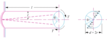
- When a machine member is subjected to two equal and opposite couples acting in parallel plane, then the machine member is said to be subjected to torsion. The stress set up by torsion is known as torsional shear stress.
- It is zero at the centroidal axis and maximum at the outer surface.

where,
ζ = Torsional shear stress induced at the outer surface of the shaft.
r = Radius of the shaft.
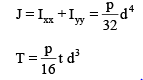
T = Torque or twisting moment.
J = Second moment of area of the section about its polar axis.
C = Modulus of rigidity.
l = length of the shaft.
θ = Angle of twist in radians on a length
Power transmitted by a shaft (in watts)
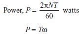
N = Speed in rpm
w = Angular speed in rad/s
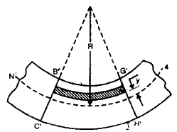
Bending Stress
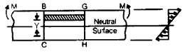
- When a beam subjected to the bending moment, in sagging (upward bending) the fibres of the upper side of the beam will be shortened due to compression and those on the lower side will be elongated due to tension, somewhere between top and bottom fibres, there is a surface at which the fibres are neither shortened nor elongated. Such a surface is called neutral plane.

where,
M = Bending moment acting at the given section
s = Bending stress
I = Moment of inertia of the cross-section about neutral axis
y = distance from the neutral axis to extreme fibre
R = Radius of curvature of beam.
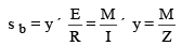

is known as section modulus.
- In case of symmetrical sections such as circular, square or rectangular, the neutral axis passes through its geometrical centre.
- In case of unsymmetrical sections such as L-section or T-section the neutral axis does not pass through its geometrical centre. In such cases, all the centroid of the section is calculated and then the distance of the extreme fibres for both lower and upper side of the section is obtained. Out of these two values, the bigger value is used in bending equation.
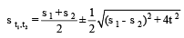
- Principal stress,
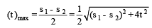
- Maximum shear stress,
- When the shaft is subjected to an axial load (P) in addition to bending and twisting moments as in the propeller shafts of ship and shafts for driving worm gears, then the resultant tensile stress or compressive stress depend upon the type of axial load.
The document Torsional & Bending Stresses in Machine Parts | Mechanical Engineering SSC JE (Technical) is a part of the Mechanical Engineering Course Mechanical Engineering SSC JE (Technical).
All you need of Mechanical Engineering at this link: Mechanical Engineering
|
5 videos|103 docs|59 tests
|
FAQs on Torsional & Bending Stresses in Machine Parts - Mechanical Engineering SSC JE (Technical)
| 1. What are torsional and bending stresses in machine parts? |  |
| 2. How do torsional and bending stresses affect machine parts? | |
Ans. Torsional and bending stresses can significantly impact the performance and durability of machine parts. Excessive torsional stress can lead to shearing or failure of shafts or axles, while excessive bending stress can cause deformation, cracking, or even fracture in components such as beams or supports. Understanding and properly managing these stresses are crucial for ensuring the reliability and safety of machine parts.
| 3. What factors contribute to torsional and bending stresses in machine parts? | |
Ans. Several factors contribute to the development of torsional and bending stresses in machine parts. These include the magnitude and direction of applied loads, the material properties of the component, the geometry and dimensions of the part, as well as the boundary conditions and supports. Analyzing these factors through mathematical models or finite element analysis helps engineers determine the maximum stress levels and design parts accordingly.
| 4. How can torsional and bending stresses be reduced in machine parts? | |
Ans. There are several strategies to reduce torsional and bending stresses in machine parts. These include optimizing the design by using appropriate geometry, such as increasing the diameter of shafts or adding reinforcing ribs to beams. Choosing materials with higher strength or stiffness properties can also help minimize stress levels. Additionally, applying surface treatments or using stress-relieving techniques during manufacturing can improve the resistance of machine parts to torsional and bending stresses.
| 5. What are the failure criteria for torsional and bending stresses in machine parts? | |
Ans. The failure criteria for torsional and bending stresses depend on the material properties of the machine part. For ductile materials, failure is typically assessed based on yielding or plastic deformation. On the other hand, for brittle materials, failure is determined by the onset of crack propagation or fracture. Design standards and guidelines provide specific limits and safety factors to ensure that machine parts can withstand the expected torsional and bending stresses without failure.
Related Exams
About this Document

6.9K Views

4.92/5
Rating

Mar 01, 2025
Last updated
Document Description: Torsional & Bending Stresses in Machine Parts for Mechanical Engineering 2025 is part of Mechanical Engineering SSC JE (Technical) preparation.
The notes and questions for Torsional & Bending Stresses in Machine Parts have been prepared according to the Mechanical Engineering exam syllabus. Information about Torsional & Bending Stresses in Machine Parts covers topics
like and Torsional & Bending Stresses in Machine Parts Example, for Mechanical Engineering 2025 Exam. Find important definitions, questions, notes, meanings, examples, exercises and tests below for Torsional & Bending Stresses in Machine Parts.
Introduction of Torsional & Bending Stresses in Machine Parts in English is available as part of our Mechanical Engineering SSC JE (Technical)
for Mechanical Engineering & Torsional & Bending Stresses in Machine Parts in Hindi for Mechanical Engineering SSC JE (Technical) course.
Download more important topics related with notes, lectures and mock test series for Mechanical Engineering
Exam by signing up for free. Mechanical Engineering: Torsional & Bending Stresses in Machine Parts | Mechanical Engineering SSC JE (Technical)
Description
Full syllabus notes, lecture & questions for Torsional & Bending Stresses in Machine Parts | Mechanical Engineering SSC JE (Technical) - Mechanical Engineering | Plus excerises question with solution to help you revise complete syllabus for Mechanical Engineering SSC JE (Technical) | Best notes, free PDF download
Information about Torsional & Bending Stresses in Machine Parts
In this doc you can find the meaning of Torsional & Bending Stresses in Machine Parts defined & explained in the simplest way possible. Besides explaining types of
Torsional & Bending Stresses in Machine Parts theory, EduRev gives you an ample number of questions to practice Torsional & Bending Stresses in Machine Parts tests, examples and also practice Mechanical Engineering
tests

Related Searches
Exam
,Torsional & Bending Stresses in Machine Parts | Mechanical Engineering SSC JE (Technical)
,Extra Questions
,Viva Questions
,Important questions
,ppt
,Free
,study material
,video lectures
,Semester Notes
,mock tests for examination
,shortcuts and tricks
,Torsional & Bending Stresses in Machine Parts | Mechanical Engineering SSC JE (Technical)
,MCQs
,Objective type Questions
,practice quizzes
,Torsional & Bending Stresses in Machine Parts | Mechanical Engineering SSC JE (Technical)
,Sample Paper
,Previous Year Questions with Solutions
,past year papers
,Summary
;


Additional Information about Torsional & Bending Stresses in Machine Parts for Mechanical Engineering Preparation
Torsional & Bending Stresses in Machine Parts Free PDF Download
The Torsional & Bending Stresses in Machine Parts is an invaluable resource that delves deep into the core of the Mechanical Engineering exam.
These study notes are curated by experts and cover all the essential topics and concepts, making your preparation more efficient and effective.
With the help of these notes, you can grasp complex subjects quickly, revise important points easily,
and reinforce your understanding of key concepts. The study notes are presented in a concise and easy-to-understand manner,
allowing you to optimize your learning process. Whether you're looking for best-recommended books, sample papers, study material,
or toppers' notes, this PDF has got you covered. Download the Torsional & Bending Stresses in Machine Parts now and kickstart your journey towards success in the Mechanical Engineering exam.
Importance of Torsional & Bending Stresses in Machine Parts
The importance of Torsional & Bending Stresses in Machine Parts cannot be overstated, especially for Mechanical Engineering aspirants.
This document holds the key to success in the Mechanical Engineering exam.
It offers a detailed understanding of the concept, providing invaluable insights into the topic.
By knowing the concepts well in advance, students can plan their preparation effectively.
Utilize this indispensable guide for a well-rounded preparation and achieve your desired results.
Torsional & Bending Stresses in Machine Parts Notes
Torsional & Bending Stresses in Machine Parts Notes offer in-depth insights into the specific topic to help you master it with ease.
This comprehensive document covers all aspects related to Torsional & Bending Stresses in Machine Parts.
It includes detailed information about the exam syllabus, recommended books, and study materials for a well-rounded preparation.
Practice papers and question papers enable you to assess your progress effectively.
Additionally, the paper analysis provides valuable tips for tackling the exam strategically.
Access to Toppers' notes gives you an edge in understanding complex concepts.
Whether you're a beginner or aiming for advanced proficiency, Torsional & Bending Stresses in Machine Parts Notes on EduRev are your ultimate resource for success.
Torsional & Bending Stresses in Machine Parts Mechanical Engineering Questions
The "Torsional & Bending Stresses in Machine Parts Mechanical Engineering Questions" guide is a valuable resource for all aspiring students preparing for the
Mechanical Engineering exam. It focuses on providing a wide range of practice questions to help students gauge
their understanding of the exam topics. These questions cover the entire syllabus, ensuring comprehensive preparation.
The guide includes previous years' question papers for students to familiarize themselves with the exam's format and difficulty level.
Additionally, it offers subject-specific question banks, allowing students to focus on weak areas and improve their performance.
Study Torsional & Bending Stresses in Machine Parts on the App
Students of Mechanical Engineering can study Torsional & Bending Stresses in Machine Parts alongwith tests & analysis from the EduRev app,
which will help them while preparing for their exam. Apart from the Torsional & Bending Stresses in Machine Parts,
students can also utilize the EduRev App for other study materials such as previous year question papers, syllabus, important questions, etc.
The EduRev App will make your learning easier as you can access it from anywhere you want.
The content of Torsional & Bending Stresses in Machine Parts is prepared as per the latest Mechanical Engineering syllabus.
|
© EduRev
|
Education Revolution
|


|


Signup to see your scores
go up within 7 days!
Access 1000+ FREE Docs, Videos and Tests
Takes less than 10 seconds to signup