Compound DC Generators
(Refer Slide Time: 00:26)
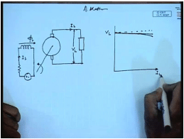
We know that a d c generator has mainly two windings. One is the armature winding another is the field winding. The armature winding supply the load the field winding can be excited from a separate d c source in which case this generator is called a separately excited generator. So, we have seen that the terminal voltage characteristics and voltage current characteristics of this generator is almost linear if we neglect armature reaction then it is exactly linear, if armature reaction is consider then it drops slightly in a nonlinear fashion for larger values of load current. This generator is very suitable for supplying loads that is require constant voltage, but it requires a external power supply.
(Refer Slide Time: 02:24)
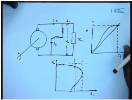
Instead of supplying the field from a external power supply the field winding can be supplied from the generator terminal itself in this case we have seen if certain conditions regarding the circuit is satisfied then the generator develops a voltage across its terminal. This process is called self excitation, and the O C C of the generator looks like this and the field circuit load line is given by straight line. So, the generator builds up to this voltage at no load this process is called self excitation the output characteristics of this generator; however, is considerably different from that of a separately excited generator in the sense that initially it behaves almost like a separately excited generator, but as the load current increases the behavior the voltage starts dropping and for large load current actually the curves looks like this.
That is instead of a voltage source these generators starts behaving like a current source. However, this phenomenon is observed at a current which is much higher than the general load current, and normally the rated current will be the generator will be much less than this maximum possible current and this generator can also be used for supplying loads that require almost constant voltage, there is other possibilities of connecting this field winding this is incidentally this machine is called the d c shunt generators there are other possibilities of connecting the field winding.
(Refer Slide Time: 05:45)
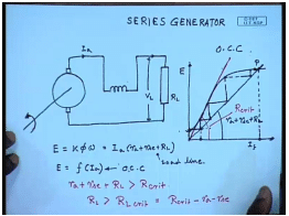
For example instead of connecting the field across the armature terminal it is possible to connect the field winding in series with the armature terminal. In, which case this is called a series generator just as a shunt generator it is possible for a series generator to self excite in order to get a open circuit characteristics of this generator. The field winding is disconnected from the supply is excited separately from a separate d c voltage source, and one can obtain the open circuit characteristics that is the plot of field current versus induced voltage like this. It should be remembered that construction winding wise the field winding that is connected across the armature terminal of the generator, and its series with the armature terminal are fundamentally different, because the field winding that is connected to the across the generator carries regulatory current therefore, it is made up of thin wires and the winding typically exhibits large resistance.
However, the series field winding is made up of thick wires, and it has fewer number of turns and it offers less resistance the resistance of a series field winding will be almost of the same order as that of the armature winding for this generator when the field winding is connected in series with the armature, and the load is kept open if the machine is rotated at a given speed constant speed then initially only the voltage due to the residual flux will appear at the terminal.
Once, this armature circuit is closed through a load then the current will start flowing depending on the resistance of the load initially this was the voltage depending on the resistance of the load some amount of current will flow.
Let us say this; however, as the current flows through the series field winding the series field winding will produce additional flux, and if the polarity of the winding connection is such that the series field flux assists the residual flux then the induced voltage will increase this will send more current, and in this process the voltage across the generator terminal will build up and finally, settle at the point p, where the load line meets the O C C. So, this is the self excitation process in a series generator. It is similar to that of a shunt generator except that the slope of the load line, now includes the armature resistance the series field resistance plus the load resistance for this generator we can write the induced voltage equal to k phi omega, and also equal to I a R a plus R s c plus R L and E is also the function of I a, which is the O C C. This is the O C C and this is the load line.
The intersection of these two will with the operating point; obviously, at no load this generator produces very little voltage, which is equal to the voltage due to the residual flux alone just like shunt generator we can also define a critical resistance here it is that value of the load line slope for which the load line is tangent to the O C C if the value of R a plus R s c this is R critical plus R L is larger than R critical then the series generator will fail to build up or in other words. If the load resistance is greater than some critical load resistance, which is equal to R critical minus R a minus R s c then this series generator will fail to build up. It should be noted that the value of the resistance R critical or R L critical is a function of the rotational speed of the generator higher the rotational speed higher is the value of this R critical. Then for a given critical resistance for a given load resistance we can also define a critical operating speed, because the induced E M F is also proportional to speed below which for a given load resistance.
(Refer Slide Time: 14:46)
 This series generator will fail to build up for example, let us assume that this is the O C C for a rotational speed N 1 then the O C C fall a different speed N 2, which is greater than or less than N 1 can be drawn by multiplying the O C C at N 1 by the ratio N 1 by N 2 or N 2 by N 1. So, let us say this is the load line corresponding to N 2 the O C C corresponding to N 2 then we it is obvious that while the generator will build up to almost the rated voltage. If it is operated at a speed N 1 it will possibly fail to build up at a rotational speed N 2, where N 2 is less than N 1.
Therefore, for any load resistance R L we can define the critical rotational speed in critical below, which this series generator in fail to build up. This concepts we have discuss in relation to shunt generator then apply similar manner to series generator we have also seen how obtain the output of voltage characteristics has a load current characteristics a for a shunt generator.
(Refer Slide Time: 17:18)
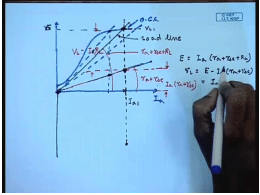
We can apply a similar method here for that we first draw the O C C of the generator at the given operating speed let us say this is the O C C on which we supper impose the load line. So, at this load with this load the terminal the armature current will have these value I a 1 and the generated voltage will be V L 1 we can plot that point let us say this is V L 1.
This is the generated voltage. So, the terminal voltage for a series generator we have seen that E equal to I a into R a plus R s c plus R L. This is the value of E and V L equal to E minus I a R a plus R s c equal to I a R L therefore, we draw another line with a slope of this slope was R a plus R s c plus R L. This slope is R a plus R s c hence the drop to this magnitude represents the drop across the armature resistance this is I a into R a plus R s c and the rest of the magnitude is I a R L which is nothing, but the load voltage. So, we see that load voltage as the load resistance is changed this curve the slope this straight line will remain fixed, but we will have different load lines, which will intersect the O C C at different points; however, the vertical distance between the point, where it intersects the O C C and the vertical line. Where it crosses the armature plus field resistance line is the terminal voltage.
(Refer Slide Time: 21:49)
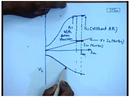
Therefore in order to draw the load characteristics of a series generator one first draws the O C C, which is a plot of induced voltage versus field current, which is same as armature current in this case, and then on the same graph draws the load line corresponding to armature resistance and the field resistance, which is for any value of load current which is same as the armature current the terminal voltage for a given value let us say I I a 1 this will be the drop I a 1 R a plus R s c, and this will be the terminal voltage V L 1, which can be plotted for different values of I a and we can get the V L versus I a which is the load characteristics of this d c generator.
Of course, it is neglected armature reactance armature reaction, which nevertheless can be included, because if we know the equivalent ampere turns of the armature reaction flux we simply subtract let us say we want to find out the terminal voltage at a load current of I a 1 including armature reaction then the we first find out the draw the line and then find out the drawback plus armature, and series resistance and then from here subtract the armature equivalent armature reaction in current and then the vertical distance of the O C C at that point gives the this is without V L 1 without armature reaction this will be V L 1 with armature reaction.
Obviously, the V L 1 if we consider armature reaction will be less compared to the case where armature reaction is not prominent. One difference of this output characteristics with the shunt generator is that the output voltage varies over a wide range depending on the load current which is expected, because the strength of the field flux is proportional to almost is dictated by the load current and as the load current reduces the field flux reduces the generated voltage reduces. So, the terminal voltage also reduces for this kind of characteristic series generator is not very much preferred for loads that require constant almost constant output voltage.
(Refer Slide Time: 26:19)
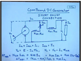
However, this principal of series excitation finds application in another type of d c generator, which are called the compound d c generator as the name suggests a compound d c generator contains two field winding one is excited from in a shunt manner, this is called the shunt field with number of turns in s h as well as a series field . For this we can write if this is the terminal volt this is the voltage across the armature and this is the voltage load voltage we can write I a equal to I s h plus I L series field current I s c equal to I L the armature terminal voltage V a equal to induced voltage E minus I a R a and the terminal voltage V L equal to V a minus I L R s c it is seen that here the shunt field winding is connected directly across the machine armature terminal. Therefore, this is called short shunt connection. It is to be it is to be appreciated that the shunt field turns and the series field turns are put on the same field post and share the same magnetic path that is the shunt ampere turns and the series ampere turns they are in series.
So, the net ampere turns that produces the field flux is given by N s h I s h plus N s e I L for this case I L equal to I a minus I s h or net.
(Refer Slide Time: 33:39)
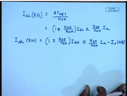
So, we can define an effective field current for this to be I s h effective to be equal to a t net by N s h and this will be given by one minus N s e by N s h I s h plus N s e by N s h I a. So, we see that the series ampere turns can be expressed in terms of effective field. So, if N s e is greater than 0 that is there is a series winding we see that the armature current flowing through it will alter the effective shunt field current and hence the induced voltage in this generator.
It should be appreciated that the series field can be connected in such a manner that it can either assist or oppose the shunt field flux hence, ideally we should use a plus minus sign here that is the series field current may add or oppose the shunt field when the series field current assists the shunt field. This is called commutability compound when it opposes the shunt field this called differentially compound of course, we can also take the effect of armature reaction in which case I s h effective will be equal to 1, normally the armature reaction flux is expressed as a in equivalent field current, which is represented by I F a r, there is another method of connecting the series field, which is called the long shunt connection in this case the shunt series field is connected first, and the shunt field is connected across the load rather than the armature.
(Refer Slide Time: 37:09)
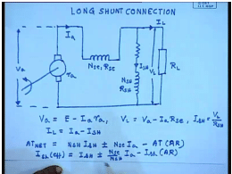
This is this voltage with the armature terminal voltage V a. So, for this long shunt connection we can write V a equal to E minus I a R a and V L equal to V a minus I a R s e. Where, and I s h equal to V L by R s h I L equal to I a minus I s h the net a t equal to N s h I s h plus minus N s e I a hence I F minus a t of armature reaction hence I effective I F h effective equal to I s h plus minus N s e by N s h I a minus I s h armature reaction. So, these are the here also either cumulative or differential compounding is possible, which is indicated by the plus minus sign just like series or shunt generator it is possible.
(Refer Slide Time: 42:02)
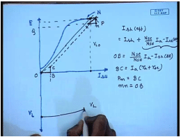
To find out the O C C and the external characteristics of compound generator the O C C is found in a similar manner as that are the separately excited generator that is for determining the O C C only the shunt field is excited of course, O C C is found out at a particular rotational speed N from this O C C it is possible to find out the terminal voltage characteristics of a compound generator. This explains the process for a long shunt connection in order to find out the external that is V L versus I a characteristics first draw the field load line with the shunt field resistance R s h.
If there is no load connected then at no load this will be the no load voltage generated V L 0, which is plotted here at any other load current corresponding armature current we can find out the terminal voltage in the following manner first let us for any armature current let us first find out the effective field current, which is given by I s h effective equal to actual I s h for cumulative compound generator it will be plus N s E by N s h I a minus I s h armature reaction first. So, this is the actual this is the actual field current with which we should add the. So, this let this be the term due to let o b equal to N s E by N s h I a for a given I a minus I s h a R and o c b c equal to I a into R a plus R s E let us draw a line parallel to the shunt field load line to intersect the O C C at a point p.
Now, at p you draw a similar triangle p M N where p M equal to b c and M N equal to o b therefore, the terminal voltage the terminal voltage at a field at a armature current of I a will be given by the position of the point N which is o q. So, for a given I am we can plot that point, which gives the terminal voltage. So, in this way we can plot the terminal voltage for different values of armature current and get the output characteristics for both long and short shunt connection and for both cumulative and differential compounding compound generators if.
(Refer Slide Time: 48:48)
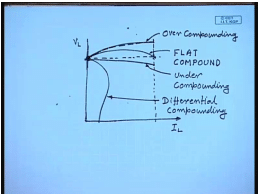
We do this exercise then we will find the output characteristics that is the characteristics of the compound generator V L versus I L can have a very wide range of variation it is possible to choose the N s e by N s h such that. The terminal voltage at no load and at full load current are equal this is called flat compounding it is also possible for the full load terminal voltage to be larger than the no load voltage. This is called over compounding and of course, this is possible for the full load voltage to be less than the no load terminal voltage this is called under compounding these characteristics are obtained when one uses cumulatively compound generator, but when a differentially generator is used the output characteristic is very different. In fact, it looks more like a shunt generator with very large current that is the output voltage drops off very fast. In fact, it behaves more or less like a current source rather than a voltage source.
This is differential compounding because of this nature differential compounding is not very much in use. So, the advantage of a compound generator is that the series field turns can be number of series field turns can be controlled to give a very wide variety of output characteristics for the cumulatively compound generator and this is practically used almost universally.
(Refer Slide Time: 52:41)
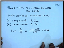
So, let us look at look to solve the few problems regarding compound generator. For example let us consider a compound generator whose rated terminal voltage is 110 volts the armature resistance R a equal to 0.06 ohm field resistance R s h equal to 25 ohm the series field resistance R s e equal to 0 0.04 ohm. The load consists of a 200 numbers of 200 number of 110 volt 55 ampere 55 watt lamps. The field excitation is adjusted to give a terminal voltage of 110 volt then find out for long shunt connection long shunt what will be the induced voltage E and the armature current I a and b for short shunt connection that will be again E and I a. So, in order to solve this problem let us first find out what is the load current I L equal to load power p L by V L no it has been mention that the load consist of 200 numbers of 55 watt lamp. So, the load power is 200 into 55 watts and the terminal voltage is 110 volt sorry this gives M e 100 ampere. So, load current in both cases is 100 ampere.
(Refer Slide Time: 55:49)
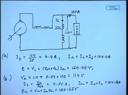
So, for the short let us see the short shunt connection looks like or long shunt connection looks like this is the motor and this is the load this current is 100 ampere this voltage is 110 volt this resistance is 25 ohm. So, I F equal to 110 by 25 equal to 4.4 ampere I a equal to I L plus I F equal to 104.4 amperes E V E equal to V L plus R s E plus R a into I a equal to120.44 volt this is for long shunt for the short shunt the armature terminal voltage is equal to 110 plus series field resistance into load current field current I F is equal to V a by R s h, which is 4.56 ampere. So, I a equal to I F plus I L equal to 104.56 ampere and E a equal to V a plus I a R a, which comes to 120.27 volts. So, that is how we can find out different parameters of compound generators.
Thank you.
This series generator will fail to build up for example, let us assume that this is the O C C for a rotational speed N 1 then the O C C fall a different speed N 2, which is greater than or less than N 1 can be drawn by multiplying the O C C at N 1 by the ratio N 1 by N 2 or N 2 by N 1. So, let us say this is the load line corresponding to N 2 the O C C corresponding to N 2 then we it is obvious that while the generator will build up to almost the rated voltage. If it is operated at a speed N 1 it will possibly fail to build up at a rotational speed N 2, where N 2 is less than N 1.


