Detailed Notes: Amplitude Modulation | Communication System - Electronics and Communication Engineering (ECE) PDF Download
Introduction
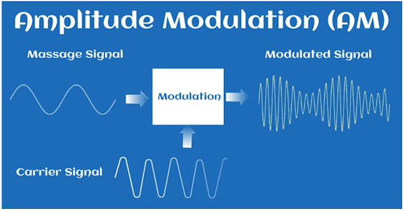
Modulation is the process of increasing and enhancing the frequency and strength of the message signal. It is the process that superimposes the original signal and the continuous high-frequency signal. In Amplitude Modulation (AM), the amplitude of the carrier wave is varied with the message signal.
The process of AM is shown in the below image:
 For example:
- Audio Signal: The audio signals are the signals with high noise. It isn't easy to transmit such signals over long distances. Hence, Modulation of audio signals is necessary for successful transmission. AM modulation is a process in which a message signal is superimposed on the radio wave as the carrier signal. It is combined with the radio carrier wave of high amplitude, which increases the magnitude of the audio signal.
Similarly, Frequency Modulation (FM) deals with the frequency variation of the carrier signal, and Phase Modulation (PM) deals with the phase variation of the carrier signal.
Analog
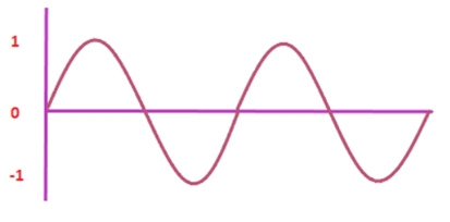
Analog refers to the continuous variation with time. We can define analog communication and analog signal as: An analog communication is a communication that continuously varies with time. It was discovered before digital communication. It requires less bandwidth for transmission with low-cost components. An analog signal is a signal that continuously varies with time. The examples of analog signal include sinusoidal waves and square waves.
A simple analog signal is shown below:
What is modulation?
When the message signal is superimposed on the carrier signal, it is known as modulation. The message signal is superimposed on the top of the carrier wave. Here, superimposed means placing a signal on the other signal. The resultant signal formed has improved frequency and strength.
The translation of the signal is required at the transmitter end for both the analog and digital signals. The translation is carried out before the signal is brought on the channel for transmission to the receiver.
- Message signal: The original signal that contains a message to be transmitted to the receiver is known as message signal.
- Carrier signal: A carrier signal is a signal with a constant frequency, which is generally high. The carrier signal waves do not require a medium to propagate.
- Baseband signal: A message signal that represents the band of frequencies is known as a baseband signal. The range of baseband signals is from 0 Hz to the cut-off frequency. It is also called an unmodulated signal or low-frequency signal.
An Analog signal is the output of a light/sound wave converted to an electrical signal. - Passband signal: It is centered at the frequency higher than the maximum component of the message signal.
Example: Let's consider an example of speech signal. It is a type of audio signal.
The speech signal has lower baseband frequencies of the range 0.3 to 3.4k Hz. If two persons want to communicate on the same channel, the baseband frequencies will interfere. It is because the lower frequencies cannot allow two baseband frequencies on the same channel. Hence, a carrier of high frequency upto 8k Hz is used with the speech signal. It increases the frequency range of the speech signal. It allows two persons to communicate on the same channel without any interference.
Need for Modulation
A communication system sends the data from the transmitter to the receiver. The data is processed and travels more than hundreds of miles before reaching the receiver. The noise during the transmission can affect the shape of the communicating signal. It further misleads the received information by reducing the signal's frequency and strength. A process is required that increases the frequency and the strength of the signal. The process in communication is known as modulation.
It is essential to transmit a signal from one place to the other in communication. Here, an original signal is replaced with the new one, increasing its frequency from f1 - f2 to f1' - f2'. It is present in the recoverable form at the receiver end.
The requirement of Modulation is based on the following factors:
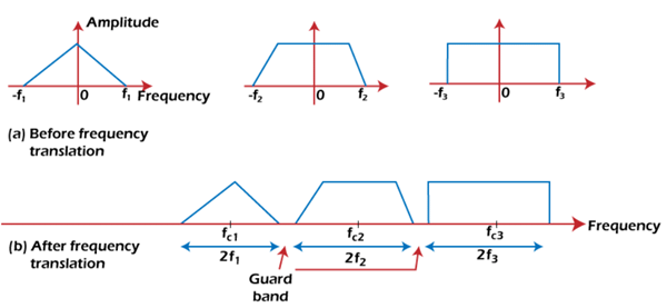
- Frequency Multiplexing: Multiplexing refers to translating multiple signals on the same channel. Suppose we have three signals to be transmitted along a single communication channel without affecting the signal's quality and data. It means that the signals should be distinguishable and recoverable at the receiving end. It can be done by translating the three signals at different frequencies. It prevents the multiple signals from intersecting.
Let the frequency range of three signals be -f1 to f1, -f2 to f2, and -f3 to f3. The signals are separated by a guard between them, as shown below: If the selected frequencies of these signals do not overlap, it can be easily recovered at the receiving end by using appropriate bandpass filters.
 - Antennas: The antennas transmit and receive signals in the free space. The length of the antenna is selected according to the wavelength of the transmitted signal.
- Narrowbanding: The signal is transmitted in free space with the help of an antenna. Suppose the frequency range is from 50 to 104 Hz. The ratio of highest to the lowest frequency will be 104/50 or 200. The length of the antenna at this ratio will become too long at one end and too short at the other end. It is not suitable for transmission. Hence, the audio signal is translated to the range (106 + 50) to (106 + 104). The ratio now will be around 1.01. It is known as narrowbanding.
Thus, the process of translation can be changed into narrowband or wideband depending on the requirements. - Common processing: Sometimes, we need to process the spectral frequency range of different signals. If there are large numbers of signals, it is better to operate in some fixed frequency range rather than the processing the frequency range of each signal.
For example:
Superheteroyne receiver
Here, a common processing block is tuned to a different frequency by using a local oscillator.
Types of Amplitude Modulation
The types of modulation are designated by the ITU (International Telecommunication Union).
There are three types of Amplitude Modulation, which are as follows:
- Single Sideband Modulation: The SSB AM is the standard method to produce sidebands on only one side of the carrier frequency. The Amplitude Modulation can produce sidebands on both sides of the carrier frequency. In SSB, it uses bandpass filters to discard one sideband. The SSB modulation process improves the bandwidth utilization and total transmission power of the transmission medium.
- Double Sideband Modulation: Double means two sidebands. The frequencies produced by the AM in DSB are symmetrical about the carrier frequency. The DSB is further categorized as DSB-SC and DSB-C. The DSB-SC (Double Sideband Suppress Carrier) modulation does not contain any carrier band, due to which its efficiency is also maximum as compared to other types of modulation. The carrier part in the DSB-SC is removed from the output component. The DSB-C (Double Sideband with Carrier) consists of the carrier wave. The output produced by the DSB-C has a carrier in combination with the message and the carrier component.
- Vestigial Sideband Modulation: Some of the information is SSB, and DSB may get lost. Hence, VSB is used to overcome the drawbacks of these two types of AM. Vestige means a section of the signal. In VSB, a section of the signal is modulated.
The original name of the AM was DSBAM (Double Side Band Amplitude Modulation) because the side bands can appear on either side of the carrier frequency.
History of Amplitude Modulation
- In 1831, an English scientist Michael Faraday discovered the electromagnetic
- In 1873, a mathematician and scientist James C Maxwell described the propagation of the EM waves.
- In 1875, A Graham Bell discovered the telephone.
- In 1887, a German physicist H Hertz discovered the existence of radio waves.
- In 1901, a Canadian engineer named R Fessenden translated the first amplitude modulated signal.
- R Fessenden discovered it using the spark-gap transmitter, which transmits the signal with the help of an electric spark.
- The practical implementation of the AM started between 1900 and 1920 through radiotelephone transmission. It was communication using the audio or speech signal.
- The first continuous Am transmitter was developed around 1906 - 1910.
- In 1915, an American theorist J R Carson initiated the mathematical analysis of the Amplitude Modulation. He showed that the single band is enough for the transmission of the audio signal.
- On 1 December 1915, J R Carson patented the SSB (Single Sideband) Modulation.
- The radio AM broadcasting become popular after the invention of vacuum tube around 1920.
Frequency Translation of Amplitude Modulation
A signal is transmitted by multiplying it with an auxiliary sinusoidal signal. It is given by:
Vm(t) = Amcosωmt
Vm(t) = Amcos2πfmt
Where,
Am is the amplitude constant
Fm is the modulating frequency
Fm = ωm/2π
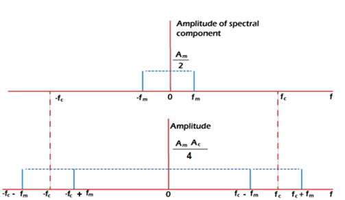
The spectral pattern will be a double-sided amplitude pattern. It consists of two lines each of amplitude Am/2, as shown below:
It is located at the frequency range from f = fm to f = -fm.
Let the auxiliary sinusoidal signal be Vc(t).
Vc(t) = ACcosωCt
By multiplying the double spectral pattern with the auxiliary signal, we get:
Vm(t). Vc(t) = Amcosωmt x ACcosωCt
Vm(t). Vc(t) = AmACcosωmt cosωCt
There are now four spectral components, as shown above.
It means that the spectral pattern now has two sinusoidal waveforms of frequency Fc + Fm and Fc - Fm. The amplitude before multiplication was Am/2. But, the components after multiplication have increases from two to four.
The amplitude now will be:
AmAc/4
1 sinusoidal component = 2 spectral components
Thus, the amplitude of each sinusoidal component will be:
AmAc/2
The spectral pattern after the multiplication is translated in both positive and negative frequency directions. If these four spectral patterns are gain multiplied, the resultant will be 6 spectral components in the form of eight sinusoidal waveforms.
Modulation Index
The modulation index is defined as the ratio of the maximum value of the message signal and the carrier signal.
It is given by:
Modulation Index = M/A
Where,
M is the amplitude of the message signal
A is the amplitude of the carrier signal
Or
Modulation index = Am/Ac
Efficiency of AM
The efficiency of Amplitude Modulation is defined as the ratio of sideband power to the total power.
Efficiency = Ps/Pt
The total power is the sum of sideband power and the carrier power.
Pt = Ps + Pc
Thus, we can also define the efficiency as:
Efficiency = Ps/ Ps + Pc
The Am signal in frequency domain can be represented as:
S(t) = AC [1 + km(t)] cosωCt
Where,
m(t) is the baseband signal
k is the amplitude sensitivity
s(t) preserves the baseband signal I its envelope
s(t) = ACcosωCt + ACkm(t)cosωCt
The first term is the carrier term and the second term is the sideband term.
The power can be represented as:
For carrier term, Power =AC2/2
For sideband term, Power =AC2k2/2 x Pm
Pm is the average power of the message signal present in the sideband term.
Efficiency = AC2k2 Pm/2 /( AC2k2 Pm/2 + AC2/2)
Efficiency= k2 Pm/1 + k2 Pm
It is the common expression used to find the power efficiency of the Amplitude Modulation.
Since there is no carrier in the Double Sideband Suppress Carrier Modulation, its efficiency is 50%. The efficiency of a single tone modulated signal in the case of the sinusoidal waveform is around 33%. The maximum efficiency of 100% can be achieved using the SSBSC (Single Side Modulation Suppress Carrier).
Advantages
The advantages of the Amplitude Modulation are as follows:
- The Amplitude modulation helps the signal to travel long distances by varying the amplitude of the message signal.
- The components used in the AM receivers and transmitters have low cost.
- AM signals are easy to modulate and demodulate.
- The modulated signal has a lower frequency that the carriers signal.
- The process of implementation of Amplitude Modulation is simple.
- The communication channel used for transmission can be a wired channel or a wireless channel. It connects the transmitter to the receiver. It also carries information from the transmitter to the receiver.
Disadvantages
AM is a widely used modulation despite of its various disadvantages. The disadvantages of the Amplitude Modulation are as follows:
- It is more susceptible to noise due to the presence of AM detectors. It affects the quality of the signal reaching the receiver.
- It has sidebands on both sides of the carrier frequency. The power in the double sidebands is not utilized 100%. The power carried by the AM waves is around 33%. It means that more than half of the power in the double-side gets wasted.
- AM requires high bandwidth, i.e., twice that of audio frequency.
Applications of Amplitude Modulation
The applications of Amplitude Modulation are as follows:
- Broadcasting: Amplitude Modulation increases the frequency of the message signal due to the presence of high frequency carrier signal. Hence, it is widely used in broadcasting due to this advantage.
- Band radios: Amplitude Modulation is used in portable two-ways radios and band radios for effective communication.
Numerical Examples
Example 1: Find the total power of the amplitude modulated signal with a carrier power 400W and modulation index of 0.8.
The formula to calculate the total power of the amplitude modulated signal is given by:
Pt = Pc (1 + m2/2)
Where,
Pt is the total power
Pc is the carrier power
M is the modulated signal
Pt = 400 (1 + (0.8)2/2)
Pt = 400 (1 + 0.64/2)
Pt = 400 (1 + 0.32)
Pt = 400 (1.32)
Pt = 528 Watts
Hence, the total power of the amplitude modulated signal is 528 watts.
Example 2: What is the maximum efficiency of the single-tone modulation signal?
The maximum efficiency of the single tone modulation signal is 33%.
The efficiency is given by the formula:
Efficiency = u2/(2 + u2)At maximum efficiency, u = 1
Efficiency = 12/(2 + 12)
Efficiency = 1/3
Efficiency % = 1/3 x 100
Efficiency % = 100/3
Efficiency % = 33.33
|
13 videos|39 docs|30 tests
|


