Force Voltage Analogy | Control Systems - Electrical Engineering (EE) PDF Download
What is the Force Voltage Analogy?
Two systems are said to be analogous to each other when they respond to inputs and disturbances in a mathematically equivalent way, even though the underlying physical processes or components are completely different. The systems can be modeled by the same differential equations and exhibit similar transient responses, steady-state behavior, and stability characteristics. For example, both systems might show exponential decay, sinusoidal behavior, or other recognizable responses. The core idea of the Force-Voltage analogy in control systems engineering is to relate mechanical systems with their electrical counterparts, by assuming Force in a mechanical system to be analogous to the Voltage in an electrical system.
Mathematical Model of Mechanical Systems
Mechanical Systems can be classified into two types based on their type of motion:
Translational Systems
Translational Systems are characterized by movement in straight lines and primarily consist of three basic elements – masses, springs and dampers. Consider the following translational mechanical system.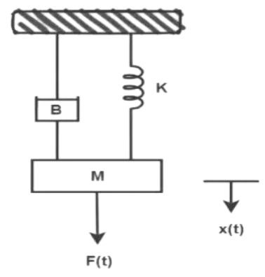 A mass ‘M’ is tethered to a fixed rigid support via a spring (with spring constant ‘K’), and the friction between the mass ‘M’ and the fixed surface is indicated by a damper with viscous damping coefficient ‘B’. An external force F(t) is being applied to this mass, causing a displacement x(t) in the direction of the applied force. Thus, the free body diagram of the Mass block can be drawn as follows.
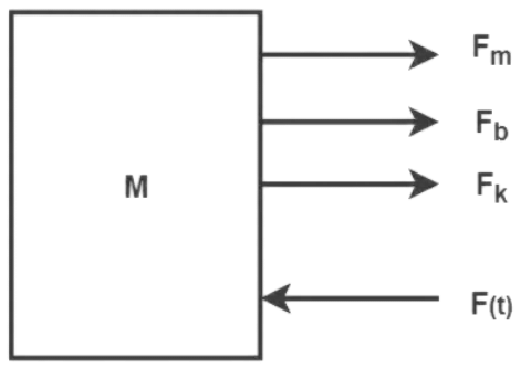
Now, according to Newtons second law, the sum of all external forces applied on a body is directly related to the acceleration it undergoes in the same direction, and inversely proportional to its mass.
∑ External Forces = Mass X Acceleration bringing the right hand side to the left,
∑ F – ma = 0
and then considering the ‘ma’ term to be a force itself, we are left with D’Alembert’s Law
∑ F = 0 essentially implying that the algebraic sum of all the forces acting on a mechanical system is zero. In other words, the sum of all applied forces is equal to the sum of all opposing forces.
Externally applied force = Inertial force + Frictional force + Restoring force of Spring 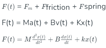 Taking the Laplace Transform of this equation (assuming initial conditions to be zero), we get the s-domain equation modeling a translational mechanical system
Mathematical Model of Electrical Systems
Next, an electrical RLC network is considered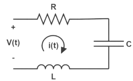
An input voltage v(t) is applied generating a current i(t) flowing through the Resistor ‘R’, Inductor ‘L’ and Capacitor ‘C’. According to Kirchhoff’s Voltage Law, the algebraic sum of potential differences in a loop must be equal to zero. Employing this law, the equation for this RLC network is given by
Writing this equation in terms of the currents flowing through the RLC elements, Taking the Laplace Transform of this equation leaves us with,
 Although this equation describes a differential model of an electrical network, it isn’t comparable to Eq. 1 derived for a mechanical system just yet since the powers of ‘s’ are one order higher in every term of the mechanical systems equation.
Since current is nothing but the rate of flow of electric charge taking the Laplace Transform of this equation gives
  Hence, modeling the electrical networks equation with replace I(s) with Q(s) instead, we get a more comparable s-domain equation modeling an electrical RLC system
Force-Voltage Analogy
- Assuming Force (F) in a mechanical system to be analogous to Voltage (V) in an electrical system
- On comparing the coefficients of the s2 terms of the differential equations modeling a mechanical and electrical system in Eq.1 and Eq.2 respectively, it can be inferred that the Mass (M) in a mechanical system is analogous to Inductance (L) in an electrical system
- Comparing the coefficients of the s1 terms of Eq.1 and Eq.2, it can be inferred that the Viscous Damping Coefficient (B) in a mechanical system is analogous to Resistance (R) in an electrical system
- Comparing the coefficients of the s0 terms of Eq.1 and Eq.2, it can be inferred that the Spring Constant (K) in a mechanical system is analogous to the Reciprocal of Capacitance (1/C) in an electrical system
- Analogies can also be drawn from the variables modeling the differential equations for the two systems. Hence, the displacement x(t) in a mechanical system is analogous to charge q(t) in an electrical system
- It can also be inferred that velocity v(t) in a mechanical system is analogous to current i(t) in an electrical system from the previous statement
Rotational Systems
This analogy can also be extended to rotational systems where a Torque balanced equation is used to model the differential equation representing the system.
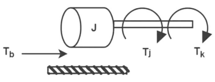 Applied Torque = Inertial Torque + Frictional Torque + Restoring Torque of Spring
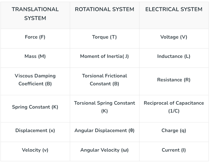
 Correlating this equation to the differential equations representing the translational and electrical systems, the following table of analogous quantities can be drawn
Translational Mechanical to Electrical System Conversion Example
Now that correlations between mechanical and electrical systems have been made, converting systems with a single set of translational, rotational or RLC elements is pretty straight forward. However, when systems have multiple sets of elements a few additional analogies have to be taken into consideration:
- Similar to how elements in series in electrical systems have the same current flowing through them, in mechanical systems, elements with the same velocity are considered to be in series
- Each Mass block (Node) in mechanical systems correspond to a closed loop in an electrical system
- Elements connected between two masses in mechanical systems correspond to elements common between two meshes in electrical systems
Let us consider the following two-mass-block translational system
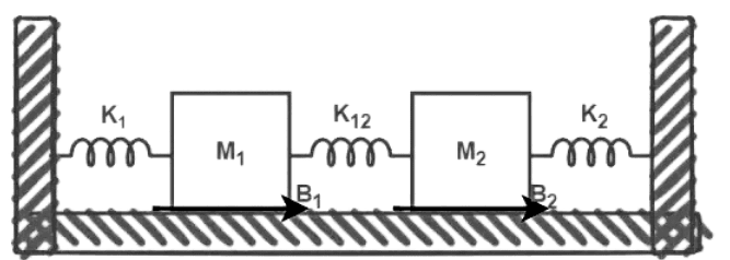
The two mass blocks imply the electrical system must have two closed loops in the electrical system, and the spring K12 is converted to a common capacitor C12 between the two loops.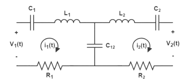
Applications of Force Voltage Analogy
- Transducers are devices that take energy from one domain as input and convert it to another energy domain as output. With respect to electromechanical systems they are typically sensors or actuators. Designing and understanding the dynamics of such systems becomes significantly easier by treating them as electrical circuits with corresponding components representing their mechanical equivalents
- By drawing parallels between mechanical and electrical parameters, existing electrical filter theory can be applied to mitigate unwanted vibrations in mechanical systems
- Roboticists also take advantage of the Force-Voltage analogy when selecting actuators, analyzing sensor data and designing control algorithms
- Investigation of mechanical properties of materials under different stress and strain conditions can be done using specialized transducers and electrical analysis
- The mechanical parts of acoustic systems like record player pickups and tonearms can be analyzed using electrical analogies
In conclusion, the Force-Voltage analogy proves to be a powerful tool in designing and analyzing control systems that utilize both mechanical and electrical components. By establishing parallels between Force and Voltage, Mass and Inductance, Displacement and Charge, Friction and Resistance and Springs and Capacitance, existing knowledge and techniques in electrical systems can be used to address problems in the mechanical world and vice-versa. It is crucial, however, to acknowledge that the accuracy of the Force-Voltage Analogy is particularly limited to linear and/or low-frequency ideal systems. Despite these limitations, the analogies present a swift practical path to designing and optimizing control systems.
|
53 videos|115 docs|40 tests
|
FAQs on Force Voltage Analogy - Control Systems - Electrical Engineering (EE)
| 1. What is the Force Voltage Analogy in mathematical modeling? |  |
| 2. How is the Force Voltage Analogy applied in converting translational mechanical systems to electrical systems? |  |
| 3. What are the key applications of the Force Voltage Analogy in engineering? |  |
| 4. How does the Force Voltage Analogy help in creating a mathematical model of mechanical systems? |  |
| 5. Can the Force Voltage Analogy be used to analyze complex systems involving both mechanical and electrical components? |  |


