HC Verma Questions and Solutions: Chapter 38: Electromagnetic Induction- 4 | HC Verma Solutions - JEE PDF Download
Q.51. A bicycle is resting on its stand in the east-west direction and the rear wheel is rotated at an angular speed of 100 revolutions per minute. If the length of each spoke is 30.0 cm and the horizontal component of the earth's magnetic field is 2.0 × 10⁻⁵ T, find the emf induced between the axis and the outer end of a spoke. Neglect centripetal force acting on the free electrons of the spoke.
Given:-
Length of the spoke of the bicycle's wheel, l = 0.3 m
Earth's magnetic field,
Length of each spoke = 30.0 cm = 0.3 m
Angular speed of the wheel,
Linear speed of the spoke,
Now,
Emf induced in the spoke of the wheel, e = Blv
= 3π × 10−6 V
= 3 × 3.14 × 10−6V
= 9.42 × 10⁻⁶ V
Q.52. A conducting disc of radius r rotates with a small but constant angular velocity ω about its axis. A uniform magnetic field B exists parallel to the axis of rotation. Find the motional emf between the centre and the periphery of the disc.
The angular velocity of the disc is ω. Also, the magnetic field of magnitude B is perpendicular to the disc.
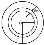
Let us take a circular element of thickness da at a distance a from the centre.
Linear speed of the element at a from the centre, v = ωa
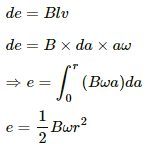
Now,
Q.53. Figure shows a conducting disc rotating about its axis in a perpendicular magnetic field B. A resistor of resistance R is connected between the centre and the rim. Calculate the current in the resistor. Does it enter the disc or leave it at the centre? The radius of the disc is 5.0 cm, angular speed ω = 10 rad/s, B = 0.40 T and R = 10 Ω.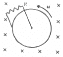
Given:-
Magnetic field perpendicular to the disc, B = 0.40 T
Angular speed, ω = 10 rad/s
Resistance, R = 10 Ω
Radius of the disc, r = 5 cm = 0.5 m
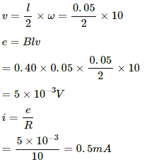
Let us consider a rod of length 0.05 m fixed at the centre of the disc and rotating with the same ω.
Now,
As the disc is rotating in the anti-clockwise direction, the emf induced in the disc is such that the centre is at the higher potential and the periphery is at the lower potential. Thus, the current leaves from the centre.
Q.54. The magnetic field in a region is given by  where L is a fixed length. A conducting rod of length L lies along the Y-axis between the origin and the point (0, L, 0). If the rod moves with a velocity
  find the emf induced between the ends of the rod.
Magnetic field in the given region,
Length of the rod on the y-axis = L
Velocity of the rod,
We will consider a small element of length dy on the rod.
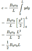
Now,
Emf induced in the element:-
de = Bvdy
And,
Q.55. Figure shows a straight, long wire carrying a current i and a rod of length l coplanar with the wire and perpendicular to it. The rod moves with a constant velocity v in a direction parallel to the wire. The distance of the wire from the centre of the rod is x. Find the motional emf induced in the rod.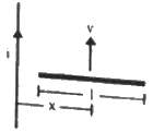
Here, the magnetic field
due to the long wire varies along the length of the rod. We will consider a small element of the rod of length da at a distance a from the wire. The magnetic field at a distance a is given by
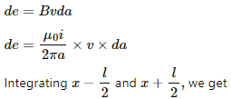
Now,
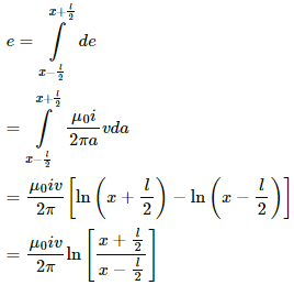
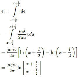
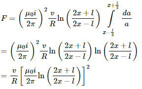
Induced emf in the rod:-
Integrating fromwe get
Q.56. Consider a situation similar to that of the previous problem except that the ends of the rod slide on a pair of thick metallic rails laid parallel to the wire. At one end the rails are connected by resistor of resistance R. (a) What force is needed to keep the rod sliding at a constant speed v? (b) In this situation what is the current in the resistance R? (c) Find the rate of heat developed in the resistor. (d) Find the power delivered by the external agent exerting the force on the rod.
(a) Here, the magnetic field
due to the long wire varies along the length of the rod.
We will consider a small element of the rod of length da at a distance a from the wire. The magnetic field at a distance a is given by
Now,
Induced emf in the rod:-
Emf induced in the rod due to the current-carrying wire:-
Now, let the current produced in the circuit containing the rod and the resistance be i'.
Force on the element:-
dF = i'Bl
And,
(b) Current,
(c) The rate of heat, that is, power, developed is given by
w = i2 R
(d) Power delivered by the external agency is the same as the rate of heat developed.
Here,
p = i2R
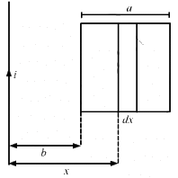
Q.57. Figure shows a square frame of wire having a total resistance r placed coplanarly with a long, straight wire. The wire carries a current i given by i = i0 sin ωt. Find (a) the flux of the magnetic field through the square frame, (b) the emf induced in the frame and (c) the heat developed in the frame in the time interval 0 to 
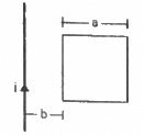
Let us consider an element of the loop of length dx at a distance x from the wire.
(a) Area of the element of loop A = adx
Magnetic field at a distance x from the wire, 20π/ω
The magnetic flux of the element is given by
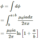
The total flux through the frame is given by
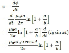
(b) The emf induced in the frame is given by
(c) The current through the frame is given by
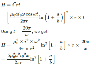
The heat developed in the frame in the given time interval can be calculated as:-
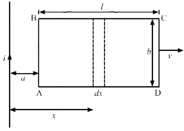
Q.58. A rectangular metallic loop of length l and width b is placed coplanarly with a long wire carrying a current i (figure). The loop is moved perpendicular to the wire with a speed vin the plane containing the wire and the loop. Calculate the emf induced in the loop when the rear end of the loop is at a distance a from the wire. solve by using Faraday's law for the flux through the loop and also by replacing different segments with equivalent batteries.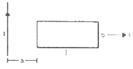
Consider an element of the loop of length dx at a distance x from the current-carrying wire.
The magnetic field at a distance x from the the current-carrying wire is given by
Area of the loop = bdx
Magnetic flux through the loop element:-
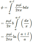
The magnetic flux through the loop is calculated by integrating the above expression.
Thus, we have
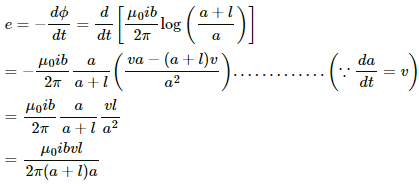
The emf can be calculated as:-
Calculation of the emf using the emf method:-
The emf. induced in AB and CD due to their motion in the magnetic field are opposite to each other.
The magnetic field at AB is given by
Now,
Length = b
Velocity = v
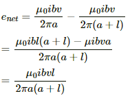
The emf induced in AB is given by
The magnetic field at CD is given by
The emf induced in side CD is given by
The net emf induced is given by
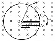
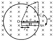
Q.59. Figure shows a conducting circular loop of radius a placed in a uniform, perpendicular magnetic field B. A thick metal rod OA is pivoted at the centre O. The other end of the rod touches the loop at A. The centre O and a fixed point C on the loop are connected by a wire OC of resistance R. A force is applied at the middle point of the rod OAperpendicularly, so that the rod rotates clockwise at a uniform angular velocity ω. Find the force.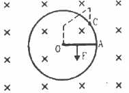
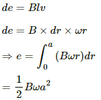
Calculation of the emf induced in the rotating rod:-
It is given that the angular velocity of the disc is ω and the magnetic field perpendicular to the disc is having magnitude B.
Let us take an element of the rod of thickness dr at a distance r from the centre.
Now,
Linear speed of the element at r from the centre, v = ωr
Because it is connected to resistance R, the current in the circuit containing the rod, wire and circular loop is given by
The direction of the current is from point A to point O in the rod.
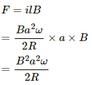
The magnitude of the force that is applied on the rod is given by
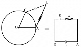
Q.60. Consider the situation shown in the figure. Suppose the wire connecting O and C has zero resistance but the circular loop has a resistance Runiformly distributed along its length. The rod OA is made to rotate with a uniform angular speed ω as shown in the figure. Find the current in the rod when ∠ AOC = 90°.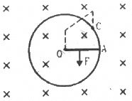
Calculation of the emf induced in the rotating rod:
It is given that the angular velocity of the disc is ω and the magnetic field perpendicular to the disc is having magnitude B.
As ∠AOC = 90°, the minor and major segments of AC are in parallel with the rod.
The resistances of the segments are R/4 and 3R/4.
The equivalent resistance is given by
The motional emf induced in the rod rotating in the clockwise direction is given by
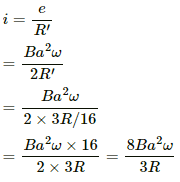
The current through the rod is given by
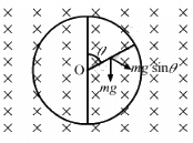
Q.61. Consider the situation shown in the figure. Suppose the circular loop lies in a vertical plane. The rod has a mass m. The rod and the loop have negligible resistances but the wire connecting O and C has a resistance R. The rod is made to rotate with a uniform angular velocity ω in the clockwise direction by applying a force at the midpoint of OA in a direction perpendicular to it. Find the magnitude of this force when the rod makes an angle θ with the vertical.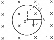
When the circular loop is in the vertical plane, it tends to rotate in the clockwise direction because of its weight.
Let the force applied be F and its direction be perpendicular to the rod.
The component of mg along F is mg sin θ.
The magnetic force is in perpendicular and opposite direction to mg sin θ.
Now,
Current in the rod:-
The force on the rod is given by
The net force passes through the centre of mass of the rod.
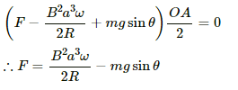
Net torque on the rod about the centre O:-
Because the rod rotates with a constant angular velocity, the net torque on it is zero.
i.e. τ = 0
Q.62. Suppose the circular loop lies in a vertical plane. The rod has a mass m. The rod and the loop have negligible resistances but the wire connecting O and C has a resistance R. The rod is made to rotate with a uniform angular velocity ω in the clockwise direction by applying a force at the midpoint of OA in a direction perpendicular to it. A battery of emf ε and a variable resistance R are connected between O and C. Neglect the resistance of the connecting wires. Let θ be the angle made by the rod from the horizontal position (show in the figure), measured in the clockwise direction. During the part of the motion 0 < θ < π/4 the only forces acting on the rod are gravity and the forces exerted by the magnetic field and the pivot. However, during the part of the motion, the resistance R is varied in such a way that the rod continues to rotate with a constant angular velocity ω. Find the value of R in terms of the given quantities.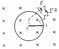
It is given that the rod is rotated with angular speed in clockwise direction.
The emf induced in the rod (e) iswith O at the lower potential and A at the higher potential.
The equivalent circuit can be drawn as:-
Because the rod rotates with uniform angular velocity, the net torque about point O is zero.
Now,
Net force on the rod, Fnet = mg cos θ - ilB
Net torque, τ = (mg cos θ - ilB).(r/2) = 0
∴ mg cos θ = ilB
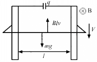
Q.63. A wire of mass m and length l can slide freely on a pair of smooth, vertical rails (figure). A magnetic field B exists in the region in the direction perpendicular to the plane of the rails. The rails are connected at the top end by a capacitor of capacitance C. Find the acceleration of the wire neglecting any electric resistance.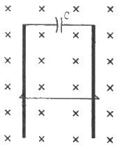
Let the velocity of the rod at an instant be v and the charge on the capacitor be q.
The emf induced in the rod is given by
e = Blv
The potential difference across the terminals of the capacitor and the ends of the rod must be the same, as they are in parallel.
And,
q = C × Blv = CBlv
Current in the circuit:-....(a = acceleration of the rod)
The force on the rod due to the magnetic field and its weight are in opposite directions.
∴ mg − ilB = ma
⇒ mg − cBla × lB = ma
⇒ ma + cB2l2a = mg
⇒ a(m + cB2l2) = mg
Q.64. A uniform magnetic field B exists in a cylindrical region, shown dotted in figure. The magnetic field increases at a constant rate dB/dt. Consider a circle of radius r coaxial with the cylindrical region. (a) Find the magnitude of the electric field E at a point on the circumference of the circle. (b) Consider a point P on the side of the square circumscribing the circle. Show that the component of the induced electric field at P along ba is the same as the magnitude found in part (a).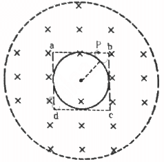
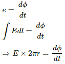
(a) The emf induced in the circle is given by
The emf induced can also be expressed in terms of the electric field as:-
E.dl = e
For the circular loop,
A = πr2
Thus, the electric field can be written as:-
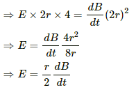
(b) When the square is considered:-
E.dl = e
For the square loop,
A = (2r)2
The electric field at the given point has the value same as that in the above case.
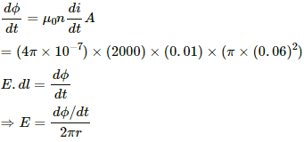
Q.65. The current in an ideal, long solenoid is varied at a uniform rate of 0.01 As−1. The solenoid has 2000 turns/m and its radius is 6.0 cm. (a) Consider a circle of radius 1.0 cm inside the solenoid with its axis coinciding with the axis of the solenoid. Write the change in the magnetic flux through this circle in 2.0 seconds. (b) Find the electric field induced at a point on the circumference of the circle. (c) Find the electric field induced at a point outside the solenoid at a distance 8.0 cm from its axis.
Given:-
Rate of change of current in the solenoid, di/dt = 0.01 A/s for 2s
∴ di/dt = 0.02 A/s
n = 2000 turns/m
R = 6.0 cm = 0.06 m
r = 1 cm = 0.01 m
(a) ϕ = BA
Area of the circle, A = π × 1 × 10⁻⁴
Now,
Δϕ = (4π × 10−7) × (2 × 103) × (π × 10−4) × (2 × 10−2)
= 16π2 × 10⁻¹⁰ Wb
= 157.91 × 10⁻¹⁰ Wb
= 1.6 × 10⁻⁵ Wb
(b) The emf induced due to the change in the magnetic flux is given by
The electric field induced at the point on the circumference of the circle is given by
(c) For the point located outside the solenoid,
The electric field induced at a point outside the solenoid at a distance of 8.0 cm from the axis is given by
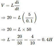
Q.66. An average emf of 20 V is induced in an inductor when the current in it is changed from 2.5 A in one direction to the same value in the opposite direction in 0.1 s. Find the self-inductance of the inductor.
Let the self-inductance of the inductor be L.
Average emf induced in the inductor, V = 20 V
Change in current, di = i2 − i1 = 2.5 − (−2.5) = 5 A
Time taken for the change, dt = 0.1 s
The voltage induced in the inductor is given by
Q.67. A magnetic flux of 8 × 10⁻⁴ weber is linked with each turn of a 200-turn coil when there is an electric current of 4 A in it. Calculate the self-inductance of the coil.
Given:
Magnetic flux linked with each turn, ϕ = 8 × 10⁻⁴ Wb
Number of turns, n = 200
Current, i = 4 A
Self-inductance is calculated as:-
= 4 × 10⁻² H
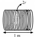
Q.68. The current in a solenoid of 240 turns, having a length of 12 cm and a radius of 2 cm, changes at a rate of 0.8 A s−1. Find the emf induced in it.
Given:
Number of turns, N = 240
Radius of the solenoid, r = 2 cm
Length of the solenoid, l = 12 cm
The emf induced in the solenoid is given by
The self-inductance of the solenoid is given by
Thus, the emf induced in the solenoid is given by
Q.69. Find the value of t/τ for which the current in an LR circuit builds up to (a) 90%, (b) 99% and (c) 99.9% of the steady-state value.
Current i in the LR circuit at time t is given by
i = i0(1 − e−t/τ)
Here,
i0 = Steady-state value of the current
(a) When the value of the current reaches 90% of the steady-state value:
⇒ 0.9 = 1 − e−t/τ
⇒ e−t/τ = 0.1
On taking natural logarithm (ln) of both sides, we get
ln (e−t/τ) = ln 0.1
(b) When the value of the current reaches 99% of the steady-state value:
On taking natural logarithm (ln) of both sides, we get
ln e−t/τ = ln 0.01
(c) When the value of the current reaches 99.9% of the steady-state value:-
⇒ e−t/τ = 0.001
On taking natural logarithm (ln) of both sides, we get
ln e−t/τ = ln 0.001
Q.70. An inductor-coil carries a steady-state current of 2.0 A when connected across an ideal battery of emf 4.0 V. If its inductance is 1.0 H, find the time constant of the circuit.
We know that time constant is the ratio of the self-inductance (L) of the coil to the resistance (R) of the circuit.
Given:
Current in the circuit, i = 2 A
Emf of the battery, E = 4 V
Self-inductance of the coil, L = 1 H
Now,
Resistance of the coil:
Time constant:
Q.71. A coil having inductance 2.0 H and resistance 20 Ω is connected to a battery of emf 4.0 V. Find (a) the current at the instant 0.20 s after the connection is made and (b) the magnetic field energy at this instant.
Given:
Self-inductance of the coil, L = 2.0 H
Resistance in the coil, R = 20 Ω
Emf of the battery, e = 4.0 V
The steady-state current is given by
The time-constant is given by
(a) Current at an instant 0.20 s after the connection is made:
i = i0(1 − e−t/τ)
= 0.17 A
(b) Magnetic field energy at the given instant:
= 0.0289 = 0.03 J
Q.72. A coil of resistance 40 Ω is connected across a 4.0 V battery. 0.10 s after the battery is connected, the current in the coil is 63 mA. Find the inductance of the coil.
Given:
Resistance, R = 40 Ω
Emf of the battery, E = 4 V
Now,
The steady-state current in the LR circuit is given by
At time, t = 0.1 s, the value of current i is 63 mA = 0.063 A
The current at time t is given by
i = i0(1 − e−t/τ)
⇒ 0.063 = 0.1(1 − e−tR/L)
⇒ 63 =100(1 − e−4/L)
⇒ 63 = 100(1 − e−4/L)
⇒ 1 − 0.63 = e−4/L
⇒ e−4/L = 0.37
= 4.024 H
= 4 H
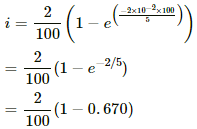
Q.73. An inductor of inductance 5.0 H, having a negligible resistance, is connected in series with a 100 Ω resistor and a battery of emf 2.0 V. Find the potential difference across the resistor 20 ms after the circuit is switched on.
Given:-
Self-inductance, L = 5.0 H
Resistance, R = 100 Ω
Emf of the battery = 2.0 V
At time, t = 20 ms ....(after switching on the circuit)
t = 20 ms = 20 × 10−3 s = 2 × 10⁻² s
The steady-state current in the circuit is given byi0 = 2/100
The time constant is given by
The current at time t is given by
i = i0(1 − e−t/τ)
= 0.00659 = 0.0066
Now,
V = iR = 0.0066 × 100
= 0.66 V
Q.74. The time constant of an LR circuit is 40 ms. The circuit is connected at t = 0 and the steady-state current is found to be 2.0 A. Find the current at (a) t = 10 ms (b) t = 20 ms, (c) t = 100 ms and (d) t = 1 s.
Given:-
Time constant of the given LR circuit, τ = 40 ms
Steady-state current in the circuit, i0 = 2 A
(a) Current at time t = 10 ms:i = i0(1 − e−t/τ)
= 2(1 − e−10/40)
= 2(1 − e−1/4)
= 2(1 − 0.7788)
= 0.4422 A
= 0.44 A
(b) Current at time t = 20 ms:i = i0(1 − e−t/τ)
= 2(1 − e−20/40)
= 2(1 − e−1/2)
= 2(1 − 0.606)
= 0.788 A
= 0.79 A
(c) Current at t = 100 ms:i = i0(1 − e−t/τ)
= 2(1 − e−100/40)
= 2(1 − e−10/4)
= 2(1 − e−5/2)
= 2(1−0.082)
=1.835 A
= 1.8 A
(d) Current at t = 1 s:i = i0(1 − e−t/τ)
= 2(1 − e−1000/40)
= 2(1 − e−100/4)
= 2(1 − e−25)
= 2 × 1 A
= 2 A
Q.75. An L-R circuit has L = 1.0 H and R = 20 Ω. It is connected across an emf of 2.0 V at t = 0. Find di/dt at (a) t = 100 ms, (b) t = 200 ms and (c) t = 1.0 s.
Given:
Inductance, L = 1.0 H
Resistance in the circuit, R = 20 Ω
Emf of the battery = 2.0 V
Now,
Time constant:
Steady-state current:
Current at time t:
i = i0(1 − e−t/τ)
or
i = i0 − i0(e−t/τ)
On differentiating both sides with respect to t, we get
(a) At time t = 100 ms,
(b) At time t = 200 ms,
(c) At time t = 1 s,
|
134 docs
|


