Logic Gates | Digital Circuits - Electronics and Communication Engineering (ECE) PDF Download
| Table of contents |
|
| Introduction |
|
| What is Logic Gate? |
|
| Types of Logic Gates |
|
| Conclusion |
|

Introduction
Logic Gate: A logic gate is a fundamental building block used to perform logical operations on binary data. It is an electronic circuit that takes one or more binary inputs (0 or 1) and produces a binary output based on predefined logic rules.
These gates are the building blocks of more complex digital circuits and are used to perform various logical operations, such as AND, OR, NOT, NAND, NOR, XOR, and XNOR.
What is Logic Gate?
A logic gate is a tiny part of a digital circuit, like a building block for electronics. It’s a small device that does basic jobs to help computers and gadgets work. You’ll find logic gates in things like phones, tablets, and memory cards. Think of a logic gate as a little decision-maker. It takes in signals, usually just 0s or 1s (like off or on), and gives out one answer. Most logic gates have two inputs and one output.
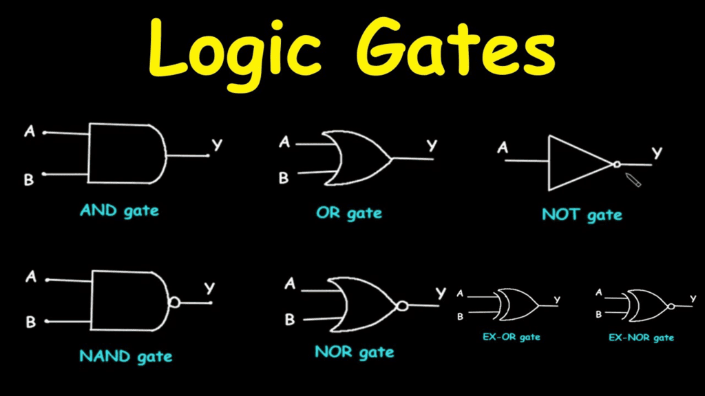
Types of Logic Gates
Logic gates are essential components in digital systems, and they come in various types. Some of the common ones include:
- OR Gate- This gate combines inputs and gives an output of "true" (1) if at least one input is true.
- AND Gate- It also takes inputs and produces "true" (1) only when all inputs are true.
- NOT Gate- This gate inverts the input; if it's "true" (1), the output will be "false" (0), and vice versa.
- XOR Gate- The Exclusive OR gate provides a "true" output when the number of true inputs is odd; otherwise, it gives a "false" output.
These gates can be used individually or combined to create more complex gates like:
- NAND Gate combines AND gate followed by a NOT gate, producing the opposite output of an AND gate.
- NOR Gate- It's an OR gate followed by a NOT gate, giving the opposite output of an OR gate.
- EXOR Gate- It's a combination of an OR gate and an AND gate, providing an output when inputs are different.
- EXNOR Gate- This gate is an inverted version of the EXOR gate, giving an output when inputs are the same.
AND Gate
The AND gate is named after the word “and” because it acts like it. In this case, 0 means “no” (false) and 1 means “yes” (true). It’s a little device with two inputs and one output. The AND gate has a symbol that looks like a curved shape with two lines going in on the left and one line coming out on the right. It only gives a “yes” (1) as the output when both inputs are “yes” (1). If even one input is “no” (0), the output is “no” (0). So, it’s like saying, “Both things have to be true for me to say yes.”
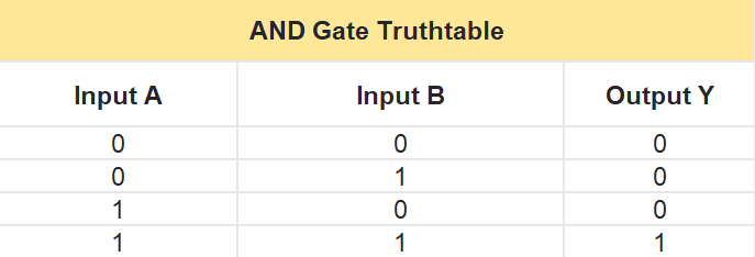
AND Gate Truth Table
The AND gate follows a simple rule written as Y = A · B, where A and B are the two inputs, and Y is the output. Here’s how it works in a table:
- If A is 0 and B is 0, then Y is 0.
- If A is 0 and B is 1, then Y is 0.
- If A is 1 and B is 0, then Y is 0.
- If A is 1 and B is 1, then Y is 1.
In short, the output is 1 only when both A and B are 1—otherwise, it’s 0.
OR Gate
The OR gate gets its name from the word “or” because it works like it. Here, 0 means “no” (false) and 1 means “yes” (true). It’s a small device with two inputs and one output. The OR gate gives a “yes” (1) as the output if at least one of the inputs is “yes” (1)—it doesn’t matter if it’s just one or both. But if both inputs are “no” (0), the output is “no” (0). Think of it like, “If even one thing is true, I’ll say yes.”
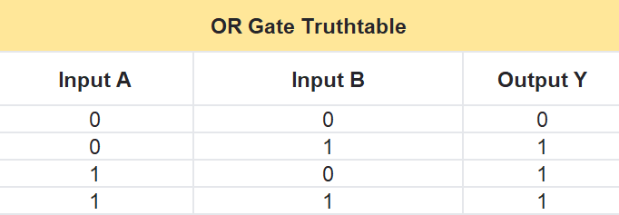
OR Gate Truth Table
The OR gate follows a simple rule written as Y = A + B, where A and B are the two inputs, and Y is the output. Here’s how it works in a table:
- If A is 0 and B is 0, then Y is 0.
- If A is 0 and B is 1, then Y is 1.
- If A is 1 and B is 0, then Y is 1.
- If A is 1 and B is 1, then Y is 1.
In short, the output is 1 if either A or B (or both) is 1—otherwise, it’s 0.
NOT Gate
The NOT gate is a simple little device called a logical inverter. It has just one input and one output. Its job is to flip whatever you give it. If you put in a 1 (yes/true), it gives you a 0 (no/false). If you put in a 0 (no/false), it gives you a 1 (yes/true). Think of it like a switch that always does the opposite: 1 turns into 0, and 0 turns into 1.
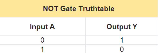
NOT Gate Truth Table
The NOT gate follows a rule written as Y = NOT A, where A is the input and Y is the output. It’s super simple because it just reverses the input. Here’s how it works in a table:
- If A is 0, then Y is 1.
- If A is 1, then Y is 0.
In short, the NOT gate takes whatever the input is and gives you the opposite.
XOR Gate
The XOR gate, short for “exclusive-OR,” works like an “either/or” rule. It has two inputs and one output. It gives a “yes” (1) if one input is “yes” (1) and the other is “no” (0)—but not if both are the same. If both inputs are “no” (0) or both are “yes” (1), the output is “no” (0). In simple words, the XOR gate says “yes” (1) when the inputs are different and “no” (0) when they’re the same. It’s like a picky OR gate that only likes it when things don’t match.
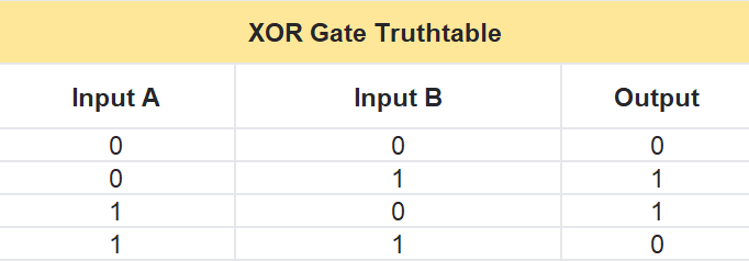
XOR Gate Truth Table
The XOR gate takes two inputs, A and B, and gives one output, Y. Here’s how it works in a table:- If A is 0 and B is 0, then Y is 0.
- If A is 0 and B is 1, then Y is 1.
- If A is 1 and B is 0, then Y is 1.
- If A is 1 and B is 1, then Y is 0.
In short, the output is 1 when A and B are different, and 0 when they’re the same.
NAND Gate
The NAND gate is like an AND gate with a twist—it flips the result. It has two inputs and one output. Normally, an AND gate says “yes” (1) when both inputs are “yes” (1), but the NAND gate says “no” (0) in that case. If at least one input is “no” (0), the output is “yes” (1). So, it’s simple: the NAND gate gives a “no” (0) only when both inputs are “yes” (1), and a “yes” (1) for everything else.
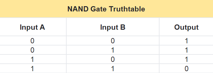
NAND Gate Truth Table
The NAND gate takes two inputs, A and B, and gives one output, Y. It’s like doing an AND operation and then flipping it with a NOT. Here’s how it works in a table:- If A is 0 and B is 0, then Y is 1.
- If A is 0 and B is 1, then Y is 1.
- If A is 1 and B is 0, then Y is 1.
- If A is 1 and B is 1, then Y is 0.
In short, the output is 1 unless both A and B are 1—then it’s 0.
NOR Gate
The NOR gate is like an OR gate with a twist—it flips the result. It has two inputs and one output. Normally, an OR gate says “yes” (1) if at least one input is “yes” (1), but the NOR gate says “no” (0) in those cases. It only says “yes” (1) when both inputs are “no” (0). So, it’s simple: the NOR gate gives a “yes” (1) only when both inputs are “no” (0), and a “no” (0) for anything else.
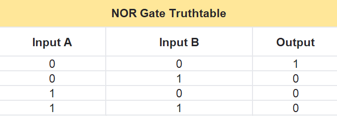
NOR Gate Truth Table
The NOR gate takes two inputs, A and B, and gives one output, Y. It’s like doing an OR operation and then flipping it with a NOT. Here’s how it works in a table:
- If A is 0 and B is 0, then Y is 1.
- If A is 0 and B is 1, then Y is 0.
- If A is 1 and B is 0, then Y is 0.
- If A is 1 and B is 1, then Y is 0.
In short, the output is 1 only when both A and B are 0—otherwise, it’s 0.
XNOR Gate
The XNOR gate, short for “exclusive-NOR,” is like an XOR gate with a flip. It has two inputs and one output. It says “yes” (1) when the inputs match—both are “no” (0) or both are “yes” (1). But if the inputs are different—one “no” (0) and one “yes” (1)—it says “no” (0). Think of it as a matcher: it’s happy (1) when things are the same and unhappy (0) when they’re not.
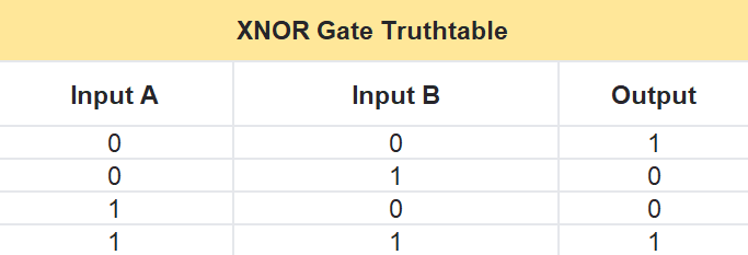
XNOR Gate Truth Table
The XNOR gate takes two inputs, A and B, and gives one output, Y. It checks if the inputs are the same or different. Here’s how it works in a table:
- If A is 0 and B is 0, then Y is 1 (they match).
- If A is 0 and B is 1, then Y is 0 (they’re different).
- If A is 1 and B is 0, then Y is 0 (they’re different).
- If A is 1 and B is 1, then Y is 1 (they match).
In short, the output is 1 when A and B are the same, and 0 when they’re different.
Conclusion
Logic gates serve as the foundational elements of digital electronics, enabling the functionality of modern computational and electronic systems. These fundamental circuits—ranging from the elementary AND, OR, and NOT gates to the derived NAND, NOR, XOR, and XNOR gates—process binary inputs (0s and 1s) according to well-defined logical rules. Each gate performs a distinct operation, whether inverting signals, evaluating conjunctions, or comparing input states, and collectively, they form the backbone of integrated circuits that drive devices such as smartphones, computers, and memory systems. A thorough understanding of logic gates and their behavior provides critical insight into the design, analysis, and optimization of digital systems, making them indispensable to engineers and technologists in the field of electronics and beyond.
|
76 videos|175 docs|70 tests
|
FAQs on Logic Gates - Digital Circuits - Electronics and Communication Engineering (ECE)
| 1. What are logic gates? |  |
| 2. How do logic gates work? | |
| 3. What are the different types of logic gates? | |
| 4. What is the significance of logic gates in digital electronics? | |
| 5. Can logic gates be combined to create more complex circuits? | |


Free
,Sample Paper
,Previous Year Questions with Solutions
,Objective type Questions
,Important questions
,practice quizzes
,Semester Notes
,Exam
,shortcuts and tricks
,study material
,mock tests for examination
,Logic Gates | Digital Circuits - Electronics and Communication Engineering (ECE)
,Summary
,Viva Questions
,Logic Gates | Digital Circuits - Electronics and Communication Engineering (ECE)
,past year papers
,video lectures
,Extra Questions
,Logic Gates | Digital Circuits - Electronics and Communication Engineering (ECE)
,ppt
,MCQs
;


Logic Gates Free PDF Download
Importance of Logic Gates
Logic Gates Notes
Logic Gates Electronics and Communication Engineering (ECE) Questions
Study Logic Gates on the App
|
© EduRev
|
Education Revolution
|


|


