Lab Manual: Refraction Through Glass Slab | Lab Manuals for Class 10 PDF Download
Objective
To trace the path of a ray of light passing through a rectangular glass slab for different angles of incidence. Measure the angle of incidence, angle of refraction, angle of emergence and interpret the result.
Materials Required
Some drawing pins, a white sheet of paper, a rectangular glass slab, a protractor, a measuring scale, a drawing board, a sharp pencil and adhesive tape.
Theory/Principle
Refraction of Light
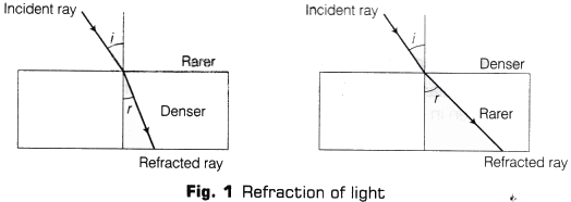
Change in path of a light ray as it passes from one medium to another medium is called refraction of light. When light travels from a rarer medium to a denser one, it bends towards the normal (i > r) and when travels from a denser medium to a rarer one, it bends away from the normal (i < r) (as shown in Fig. 1).
 where, i = angle of incidence and r = angle of refraction
Note: A medium in which the speed of light is more is known as optically rarer medium and the medium in which speed of light is lesser is known as optically denser medium.
Refraction through a Rectangular Glass Slab
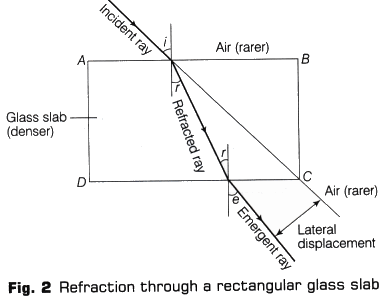
When a light ray enters in a glass slab, then the emergent ray is parallel to the incident ray but it is shifted sideward slightly. In this case, refraction takes place twice; first when ray enters glass slab from air and second when exits from glass slab to air.
Both refractions have been shown in Fig. 2 (here glass slab is denser medium and air is rarer medium). The extent of bending of the ray of light at opposite parallel faces AB and CD of rectangular glass slab is equal and opposite. So, the ray emerging from face CD is parallel to incident ray but shifted sideward slightly.

Lateral Displacement
The perpendicular distance between the emergent ray and incident ray when the light passes out of a glass slab is called lateral displacement.
Note: Angle of incidence = angle of emergence, i.e. ∠i = ∠e
if the incident ray falls normally to the surface of glass slab, then there is no bending of the ray of light, it goes straight without any deviation.
Procedure
- Fix a white sheet of paper on a drawing board.
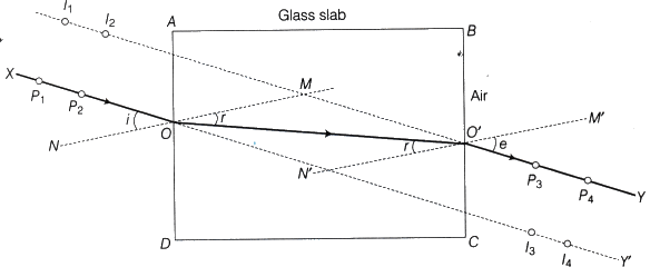
- Place the rectangular glass slab in the middle of the paper and mark its boundary ABCD with the pencil as given in Fig. 3.

Fig. 3 The images of pins P1 and /P2 appear to be at I1 and l2 when viewed through the face BC while I3 and I4 show the position of the images of pins P3 and P4 when viewed through the face AD
- Remove the rectangular glass slab. Draw a thin line XO directing towards O and inclined to the face AD of the glass slab at any angle preferably between 30° and 60°. It is advisable to take point 0 in the middle of the face AD. Replace the glass slab exactly over the boundary marked on the paper.
- Fix two pins P1 and P2 vertically about 5 cm apart by gently pressing their heads with thumb on the line XO.
- Observe the images of pins P1 and P2 through the face BC of the rectangular glass slab. While observing the images of the pins P1 and P2 through the face BC of the glass slab, fix two more pins at points P3 and P4 such that feet of all the pins appear to be in a straight line. In other words, the pins P3 and P4 are collinear with the images of pins P1 and P2.
- Remove the pins and the glass slab and mark the positions of the feet of all the four pins. Join points that mark the positions of the pins P3 and P4 and extend the line upto point O’ where it meets the face BC. Also, join the points O and O’ as given in the Fig. 3, where XOO’Y show the path of a ray of light passing through the glass slab. The line XP1P2O represents the incident ray. Line OO’ shows the path of refracted ray in glass slab while line O’P3P4Y shows the emergent ray.
- Draw the normal NOM to the face AD at the point of incidence O and similarly, the normal M’O’N’, to the face BC at point O’. Measure the angle of incidence XON (∠i), angle of refraction MOO’ (∠r) and angle of emergence M’O’Y (∠e).
- Record the values of ∠i, ∠r and ∠e in the observation table.
- Repeat the experiment for two more angles of incidence in the range 30° to 60° and record the values of angles r and e in each case.
Observations and Calculations

And we know that,
Angle of deviation (∠δ) = Angle of incidence – Angle of emergence
For observation 1, ∠δ1 = ∠i1 – ∠e1 = ………….
For observation 2, ∠δ2 = ∠i2 – ∠e2 = ………..
For observation 3, ∠δ3 = ∠i3 – ∠e3 = ……………..
Result
- The path of a ray of light passing through a rectangular glass slab is traced on the plane sheet and is shown by the ray XOO’Y in Fig. 3.
- The relations between the angle of incidence, angle of refraction and angle of emergence are obtained through different observations.
- From observations, ∠r < ∠i in each case, thus the ray entering from air to glass bends towards the normal.
- From observation, ∠i = ∠e, the emergent ray emerging out of the rectangular glass slab, is parallel to, but laterally displaced with respect to the incident ray.
- Angle of refraction (∠r) increases with increase in angle of incidence (∠i).
Precautions
- The glass slab should be perfectly rectangular with all its faces smooth.
- The tips of pins P1, P2, P3 and P4 should be sharp. These pins fixed on the sheet of paper may not be exactly perpendicular to the plane of paper. Thus, if their heads appear to be collinear, their feet may not be so, Therefore, it must be important to look at the feet of pins and their images while ascertaining collinearity between them. The mark of the pointed end or the foot of a pin on the paper must be considered while marking its position.
- The distance of 5cm between the pins P1 and P2 or P3 and P4 must be carefully maintained to obtain an accurate direction of incident ray and that of emergent ray.
- Take the angle of incidence preferably between 30° and 60°.
- Thin lines should be drawn using a sharp pencil to obtain accuracy.
- The angles should be measured accurately using a good quality protractor having clear markings by keeping the eye above the marking.
Sources of Error
- Drawing board may be hard.
- Drawing pins may not be fixed perpendicularly.
- Eyes may not be kept along the plane of paper in line, while observing the images.

|
Explore Courses for Class 10 exam
|

|


