Electrical Engineering (EE) Exam > Electrical Engineering (EE) Notes > Signals and Systems > Laplace Transform
Laplace Transform | Signals and Systems - Electrical Engineering (EE) PDF Download
| Table of contents |

|
| Need for Laplace Transform |

|
| Laplace Transform |

|
| Region of Convergence |

|
| Properties of ROC |

|
| Conclusion |

|
Need for Laplace Transform
Till now, we have been dealing with continuous and discrete domains. Then we studied the relationships involved in using the transform domains. A system operates in a natural domain but it can be well understood in transform domains.

- The advantage of transform domains is that a few of the properties that may not be observed in natural domains are clear in transform domains. Most of the LTI(Linear Time Invariant) Systems act in the time domain but they are more clearly described in the frequency domain instead.
- Till now, we have seen the importance of Fourier analysis in solving many problems involving signals and LTI systems. Now, we shall deal with signals and systems which do not have a Fourier transform.
What was so special about Fourier transform in the case of LTI systems?
- We found that the continuous-time Fourier transform(F.T.) is a tool to represent signals as linear combinations of complex exponentials. The exponentials are of the form est with s = jω and ejω is an eigenfunction of the LSI(Linear Shift Invariant) system. Also, we note that the Fourier Transform only exists for signals that can be absolutely integrated and have finite energy.
- This observation leads to a generalization of the continuous-time Fourier transform by considering a broader class of signals using the powerful tool of "Laplace transform".
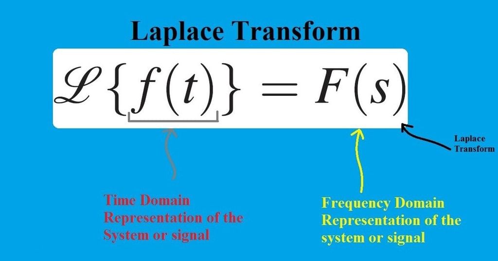 Laplace Transform
 - It will be trivial to note that the L.T. can be used to get the discrete-time representation using relevant substitutions. This leads to a link with the Z-Transform and is very handy for digital filter realization/designing. Also, it will be helpful to note that the properties of the Laplace Transform and Z-Transform are quite similar.
Laplace Transform
The response of a Linear Time-Invariant system with impulse response h(t) to a complex exponential input of the form est can be represented in the following way:
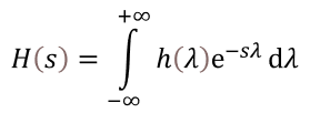
Where H(s) is known as the Laplace Transform of h(t).
- We notice that the limits are from [ -∞ to + ∞] and hence this transform is also referred to as Bilateral or Double-sided Laplace Transform. There exists a one-to-one correspondence between the h(t) and H(s), i.e., the original domain and the transformed domain. Therefore, L.T. is a unique transformation, and the 'Inverse Laplace Transform' also exists.
- Note that est is also an eigenfunction of the LSI system only if H(s) converges. The range of values for which the expression described above is finite is called the Region of Convergence (ROC). In this case, the Region Of Convergence is Re(s) > 0.
- Thus, the Laplace transform has two parts, which are the expression and the region of convergence, respectively. The region of convergence of the Laplace transform is essentially determined by Re(s). Here onwards, we will consider trivial examples for a better understanding of the ROC.
Question for Laplace TransformTry yourself:Laplace transform of any function changes it domain to s-domain.
View Solution
Region of Convergence
- Consider that the impulse response h(t) = et u(t).
Thus we notice that by multiplying by the term u(t) we are effectively considering the unilateral Laplace Transform whereby the limits tend from 0 to +∞. - Also, we notice that h(t) is not Fourier transformable as it is not integrable.
Consider the Laplace transform of h(t) as shown below: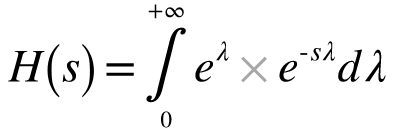
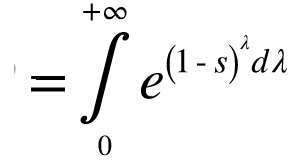
- As stated earlier, the symbol s is a complex number and is defined as s = σ + jΩ.
Substituting s in the above equation we get:
- Observing the above equation closely, we realize that firstly H(s) converges if and only if,

- We analyze the part (1-σ) as follows:
For a decaying e(1-σ)λ it is essential that (1 - σ )< 0. This implies that ( σ > 1), which means that the Real part of 's' is greater than '1' which is also denoted as Re(s) > 1. - This is what defines the " Region of Convergence " in a S-Complex Plane. The ROC of the Laplace Transform is always determined by the Re(s). The ROC, in general, gives us an idea of the stability of a system and is also a representation of the poles-zero plot of a system. It is essential to note that the ROC never includes poles.
- Evaluation of the integral yields:
- We observe that there is a single pole at s=1. Since the Region of Convergence cannot contain poles; therefore ROC starts from '1' and tends outwards to infinity.
- est in physical systems: We consider the real part of est, where, s = σ + jΩ.
- Such a response is visible in RLC (Resistance-Inductance and Capacitance) systems. It is not only visible in the electrical field but also in other disciplines like the mechanical field. In such cases, the above expression is multiplied by a polynomial or a combination of such expressions.
What is the need to consider the region of convergence while determining the Laplace transform?
- If we consider the signals e-atu(t) and -e-atu(-t) we note that although the signals are differing, their Laplace Transforms are identical which is 1/( s+a). Thus we conclude that to distinguish L.T's uniquely their ROC's must be specified.
Question for Laplace TransformTry yourself:Find the Laplace transform of u(t) and its ROC.
View Solution
Properties of ROC
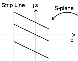
- The ROC of F(S) consists of strips parallel to jω-axis in complex variable plane (S-plane). We know that the ROC is dependent only on the real parts of 'S' which is 'σ'.
- The ROC does not contain any poles. Since if this happens then the Laplace Transform becomes infinity. For example, if F(S)= 1/(s-1) then the ROC cannot contain s =1 because at this point the L.T becomes infinity.
- If x(t) is a time-limited signal and is Laplace Transformable, then its ROC will be the entire S-plane.
Example: the ROC for δ(t)(Impulse function) is the entire S-plane. If x(t) is a right-sided sequence then ROC: Re{s} > σo.
If x(t) is a left-sided sequence then ROC: Re{s} < σo.
If x(t) is a two-sided sequence then ROC is the combination of two regions.
- The region of convergence is always between two vertical lines in the s-plane. These vertical lines need not be in finite region. But note that the ROC is always simply connected but not multiply-connected in the s-plane.
This fact can be explained by the following illustration:Let H1(s) and H2(s) be the respective Laplace transforms of the first and second terms.
- H1(s) and H2(s) converge in the region Re(s) > 1 and Re(s) < 1 respectively. But, h(t) doesn't have any Laplace transform due to no common ROC where both H1(s) and H2(s) converge.
Conclusion
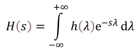 is called the Laplace Transform of h(t) and the Region of Convergence (ROC) of the Laplace transform is essentially determined by the real part of the complex number 's' denoted as Re(s).
- Two different functions may have the same Laplace Transform, so the only way to uniquely describe them is by means of ROC.
- The ROC consists of strips parallel to the J ω -axis, it does not include poles and is always simply-connected.
The document Laplace Transform | Signals and Systems - Electrical Engineering (EE) is a part of the Electrical Engineering (EE) Course Signals and Systems.
All you need of Electrical Engineering (EE) at this link: Electrical Engineering (EE)
|
41 videos|70 docs|33 tests
|
FAQs on Laplace Transform - Signals and Systems - Electrical Engineering (EE)
| 1. What is Laplace Transform? |  |
Ans. Laplace Transform is a mathematical operation that transforms a function of time into a function of a complex variable s. It is commonly used in engineering and physics to solve differential equations and analyze the behavior of linear systems.
| 2. How is Laplace Transform useful in electronics and communication engineering? |  |
Ans. Laplace Transform is used in electronics and communication engineering to analyze and solve linear time-invariant (LTI) systems. It helps in studying the response of circuits to different input signals, such as step, impulse, or sinusoidal signals. Laplace Transform also simplifies the process of solving differential equations that arise in circuit analysis and system design.
| 3. Can you give an example of Laplace Transform in electronics and communication engineering? |  |
Ans. Sure! Let's consider a simple RC circuit with a resistor R and a capacitor C connected in series. By applying the Laplace Transform to the differential equation governing the circuit, we can easily find the transfer function and analyze the frequency response of the circuit.
| 4. What are the advantages of using Laplace Transform in circuit analysis? |  |
Ans. The advantages of using Laplace Transform in circuit analysis are:
1. It simplifies the analysis of complex circuits by converting differential equations into algebraic equations.
2. It allows for the analysis of circuits under different input signals, such as step, impulse, or sinusoidal signals.
3. It provides a systematic and efficient method to determine the response of circuits to different input signals.
4. It helps in understanding the behavior of circuits in the frequency domain, allowing for the design of filters and other frequency-dependent components.
| 5. Are there any limitations or drawbacks of using Laplace Transform in circuit analysis? |  |
Ans. Yes, there are a few limitations of using Laplace Transform in circuit analysis:
1. It assumes linearity and time-invariance of the system, which may not hold true for all practical circuits.
2. It requires the initial conditions of the circuit to be known, which can be challenging in some cases.
3. It may not provide an intuitive understanding of the circuit behavior, as it deals with complex variables and transforms the time-domain into the frequency-domain.
4. It may not be suitable for analyzing non-linear circuits or circuits with switching elements, as it is primarily designed for linear time-invariant systems.
Related Searches


