Network Topology Matrices | Network Theory (Electric Circuits) - Electrical Engineering (EE) PDF Download
Matrices Associated with Network Graphs
Following are the three matrices that are used in Graph theory.
- Incidence Matrix
- Fundamental Loop Matrix
- Fundamental Cut set Matrix
Incidence Matrix
An Incidence Matrix represents the graph of a given electric circuit or network. Hence, it is possible to draw the graph of that same electric circuit or network from the incidence matrix.
We know that graph consists of a set of nodes and those are connected by some branches. So, the connecting of branches to a node is called as incidence. Incidence matrix is represented with the letter A. It is also called as node to branch incidence matrix or node incidence matrix.
If there are ‘n’ nodes and ‘b’ branches are present in a directed graph, then the incidence matrix will have ‘n’ rows and ‘b’ columns. Here, rows and columns are corresponding to the nodes and branches of a directed graph. Hence, the order of incidence matrix will be n × b.
The elements of incidence matrix will be having one of these three values, +1, -1 and 0.
- If the branch current is leaving from a selected node, then the value of the element will be +1.
- If the branch current is entering towards a selected node, then the value of the element will be -1.
- If the branch current neither enters at a selected node nor leaves from a selected node, then the value of element will be 0.
Procedure to find Incidence Matrix
Follow these steps in order to find the incidence matrix of directed graph.
- Select a node at a time of the given directed graph and fill the values of the elements of incidence matrix corresponding to that node in a row.
- Repeat the above step for all the nodes of the given directed graph.
Example
Consider the following directed graph.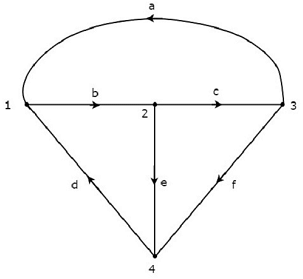
The incidence matrix corresponding to the above directed graph will be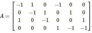 The rows and columns of the above matrix represents the nodes and branches of given directed graph. The order of this incidence matrix is 4 × 6.
By observing the above incidence matrix, we can conclude that the summation of column elements of incidence matrix is equal to zero. That means, a branch current leaves from one node and enters at another single node only.
Note : If the given graph is an un-directed type, then convert it into a directed graph by representing the arrows on each branch of it. We can consider the arbitrary direction of current flow in each branch.
Fundamental Loop Matrix
Fundamental loop or f-loop is a loop, which contains only one link and one or more twigs. So, the number of f-loops will be equal to the number of links. Fundamental loop matrix is represented with letter B. It is also called as fundamental circuit matrix and Tie-set matrix. This matrix gives the relation between branch currents and link currents.
If there are ‘n’ nodes and ‘b’ branches are present in a directed graph, then the number of links present in a co-tree, which is corresponding to the selected tree of given graph will be b-n+1.
So, the fundamental loop matrix will have ‘b-n+1’ rows and ‘b’ columns. Here, rows and columns are corresponding to the links of co-tree and branches of given graph. Hence, the order of fundamental loop matrix will be (b - n + 1) × b.
The elements of fundamental loop matrix will be having one of these three values, +1, -1 and 0.
- The value of element will be +1 for the link of selected f-loop.
- The value of elements will be 0 for the remaining links and twigs, which are not part of the selected f-loop.
- If the direction of twig current of selected f-loop is same as that of f-loop link current, then the value of element will be +1.
- If the direction of twig current of selected f-loop is opposite to that of f-loop link current, then the value of element will be -1.
Procedure to find Fundamental Loop Matrix
Follow these steps in order to find the fundamental loop matrix of given directed graph.
- Select a tree of given directed graph.
- By including one link at a time, we will get one f-loop. Fill the values of elements corresponding to this f-loop in a row of fundamental loop matrix.
- Repeat the above step for all links.
Example
Take a look at the following Tree of directed graph, which is considered for incidence matrix.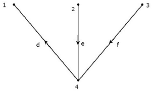 The above Tree contains three branches d, e & f. Hence, the branches a, b & c will be the links of the Co-Tree corresponding to the above Tree. By including one link at a time to the above Tree, we will get one f-loop. So, there will be three f-loops, since there are three links. These three f-loops are shown in the following figure.
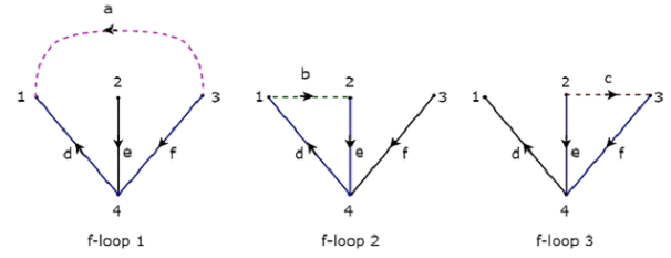 In the above figure, the branches, which are represented with colored lines form f-loops. We will get the row wise element values of Tie-set matrix from each f-loop. So, the Tie set matrix of the above considered Tree will be
 The rows and columns of the above matrix represents the links and branches of given directed graph. The order of this incidence matrix is 3 × 6.
The number of Fundamental loop matrices of a directed graph will be equal to the number of Trees of that directed graph. Because, every Tree will be having one Fundamental loop matrix.
Fundamental Cut-set Matrix
Fundamental cut set or f-cut set is the minimum number of branches that are removed from a graph in such a way that the original graph will become two isolated subgraphs. The f-cut set contains only one twig and one or more links. So, the number of f-cut sets will be equal to the number of twigs.
Fundamental cut set matrix is represented with letter C. This matrix gives the relation between branch voltages and twig voltages.
If there are ‘n’ nodes and ‘b’ branches are present in a directed graph, then the number of twigs present in a selected Tree of given graph will be n-1. So, the fundamental cut set matrix will have ‘n-1’ rows and ‘b’ columns. Here, rows and columns are corresponding to the twigs of selected tree and branches of given graph. Hence, the order of fundamental cut set matrix will be (n-1) × b.
The elements of fundamental cut set matrix will be having one of these three values, +1, -1 and 0.
- The value of element will be +1 for the twig of selected f-cutset.
- The value of elements will be 0 for the remaining twigs and links, which are not part of the selected f-cut set.
- If the direction of link current of selected f-cut set is same as that of f-cutset twig current, then the value of element will be +1.
- If the direction of link current of selected f-cut set is opposite to that of f-cutset twig current, then the value of element will be -1.
Procedure to find Fundamental Cut-set Matrix
Follow these steps in order to find the fundamental cut set matrix of given directed graph.
- Select a Tree of given directed graph and represent the links with the dotted lines.
- By removing one twig and necessary links at a time, we will get one f-cut set. Fill the values of elements corresponding to this f-cut set in a row of fundamental cut set matrix.
- Repeat the above step for all twigs.
Example
Consider the same directed graph, which we discussed in the section of incidence matrix. Select the branches d, e & f of this directed graph as twigs. So, the remaining branches a, b & c of this directed graph will be the links.
The twigs d, e & f are represented with solid lines and links a, b & c are represented with dotted lines in the following figure.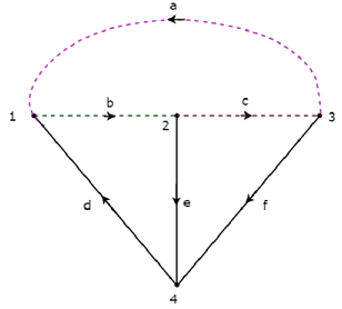 By removing one twig and necessary links at a time, we will get one f-cut set. So, there will be three f-cut sets, since there are three twigs. These three f-cut sets are shown in the following figure.
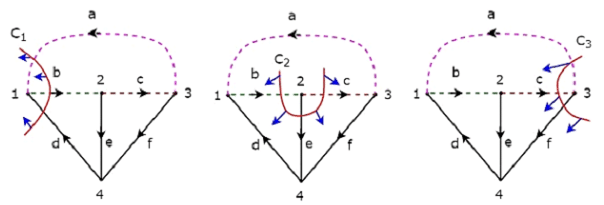 We will be having three f-cut sets by removing a set of twig and links of C1, C2 and C3. We will get the row wise element values of fundamental cut set matrix from each f-cut set. So, the fundamental cut set matrix of the above considered Tree will be
 The rows and columns of the above matrix represents the twigs and branches of given directed graph. The order of this fundamental cut set matrix is 3 × 6.
The number of Fundamental cut set matrices of a directed graph will be equal to the number of Trees of that directed graph. Because, every Tree will be having one Fundamental cut set matrix.
|
73 videos|139 docs|62 tests
|


