Priority Encoders | Analog and Digital Electronics - Electrical Engineering (EE) PDF Download
Priority Encoders
Binary Encoders generally have a number of inputs that must be mutually exclusive, i.e. only one of the inputs can be active at any one time. The encoder then produces a binary code on the output pins, which changes in response to the input that has been activated.
Priority Encoding
Because it is always possible when using input switches that more than one input may be active at a single time, most encoders of this type feature ‘priority encoding’ where, if more than one input is made active at the same time, the output will select only the most significant active input. For example, if 6 and 7 are pressed together the BCD output will indicate 7. The Pinout diagram for the 74HC147 10-To-4-line priority encoder from NXP (Philips Semiconductors) is illustrated in Fig.4.4.1.
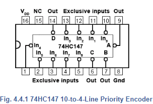
Depending on the encoding purpose, each each different IC has its own particular method for solving encoding problems. For example, a simple decimal to BCD (or 10-to-4 line) encoder would be expected to have ten input pins, but in fact the 74HC147 has only 9. The tenth condition (zero) is assumed to be present because when none of the 1 to 9 input pins is active, this must indicate zero.
The input pins may be used to connect to switches on a decimal keypad, and the encoder would output a 4-bit BCD code, (00002 to 10012) depending on which key has been pressed, or simply to identify which one of ten input lines in a circuit is active, by outputting an appropriate number in four bit BCD code.
Chip Enable Inputs
Some other encoder ICs also feature extra inputs and outputs that allow several ICs to be connected together to achieve more flexibility in the numbers of input and output lines available. These include ENABLE inputs, (typically labelled E), which may consist of one or more input pins that need to have a particular logic level applied (usually logic 0) in order to activate the encoding action. In the absence of a correct ENABLE signal the output pins of the IC will remain in their inactive state.
Switch Bounce
One problem with combinational logic circuits is that unintended changes in output data can occur during the times when the outputs of the IC are changing. This can be due to problems such as switch contacts ‘bouncing’ as they close, creating rapid and unpredictable changes in logic levels for a very short time, however logic IC operate at high speed and will respond to these very fast changes.
Race Hazards
Problems can also occur due to ‘race hazards’ where different paths that digital signals take through a logic circuit may have different numbers of gates. For example two logic signals that change simultaneously at two circuit inputs may take different routes through the circuit before being applied to some common gate later in the circuit. However, if one signal passes through six gates for example, while the other signal passes through seven gates, each of the signals will have encountered a different total propagation delay due to the different number of gates they encountered. Therefore they will each arrive at the common gate at slightly different times, and so for a very short time an unexpected logic level may occur at that gate output.
In using combinational logic ICs such as an encoder, problems like switch bounce and race hazards must be allowed for, and one (though not necessarily the best) solution can be to temporarily make the ENABLE pin high during times when data is likely to change. This disables the encoder for a short time until the signal data has settled at its new state, so that there is no chance of errors at the output during changes of input signals.
74HC148 8-to-3-Line Encoder
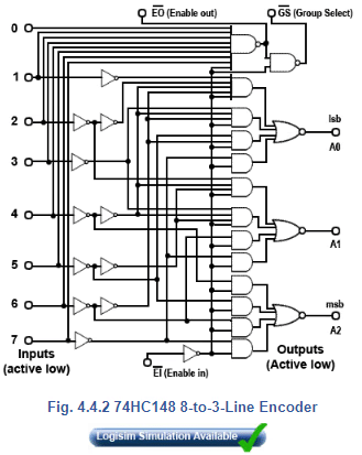
The 74HC148 also uses priority encoding and features eight active low inputs and a three-bit active low binary (Octal) output. The internal logic of the 74HC148 is shown in Fig. 4.4.2
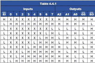
The IC is enabled by an active low Enable Input (EI), and an active low Enable output (EO) is provided so that several ICs can be connected in cascade, allowing the encoding of more inputs, for example a 16-to-6-line encoder using two 8-to-3 encoders. The CMOS 74HC148 also uses active low inputs and outputs. The operation of the 74HC148 can be seen from its truth table shown in Table 4.4.
Notice from Table 4.4.1 that the IC is only active when EI is low, and also that for each input selected by a low logic level (L), all lower value inputs indicate ‘Don’t Care’, typical of priority encoding.
Two further outputs are used for connecting additional 74HC148 ICs in cascade.
The EI input is normally used on the most significant IC and whenever an input on this IC is selected, the output goes high (disabling any less significant ICs), and the Group Select
output goes low indicating that the group of outputs of this IC are active.
16-to-4-Line Encoder
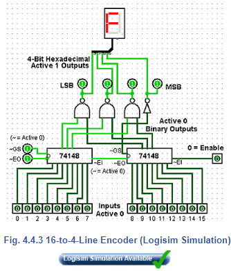
Fig 4.4.3 shows a simulation created in Logisim, which demonstrates how two 74HC148 ICs can be connected in cascade to make a 16-to-4-line encoder. Notice how is used to enable the most significant encoder, and how
in the centre of the diagram are used to cascade the ICs. As the output (000016 to FFFF16) will now require 4 bits. The
(Group Select) pin, which changes to its low logic state when any input on the most significant IC is active, is used to create the fourth output bit, (23) for any output value above 7.
In this simulation, available from Module 4.6 the active low outputs of the encoder have been inverted to provide active high inputs to the hexadecimal display.
Diode Matrix Encoders
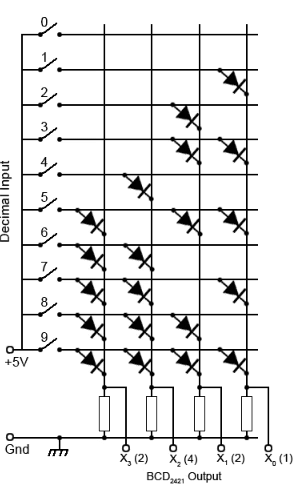
Where encoders are needed for non-standard applications, they can also be implemented using a diode matrix, such as the decimal-to-BCD2421 encoder shown in Fig 4.4.4.
In this example, as any one of the ten switches is closed +5V is applied to just one of the horizontal lines. Any diode that has its anode connected to that horizontal line and its cathode connected to a vertical line (that is held at zero volts by a resistor connected to Gnd) will conduct.
When current flows through any of the resistors, the top of that resistor will be at +4.4V (i.e. +5V minus a 0.6V drop in across the diode), which will be seen by the output as logic 1.
For example if switch 6 is closed, the two diodes connected between line 6 and columns X3 and X2 will conduct, making outputs X3 and X2 logic 1 and giving a binary2421 output word of 11002 (or 2+4 =610).
This particular diode matrix will therefore give an output in BCD2421 code from 00002421 to 11112421 for closure of switches 0 to 9.
Many other output sequences are possible therefore, by using different arrangements of the diode positions.
Although the encoder circuits described in this module may be used in a number of useful encoding situations, they have some features that limit their use for realistic keyboard encoding.
• Priority encoders do not sense information from two or more keys that are pressed at the same time.
• Switches on keypads normally contact for only a brief time, these basic encoders are not able to store and remember the data input from a pressed key once it is released.
• When a switch is closed the contacts may ‘bounce’ giving several brief 1 and 0 logic states, when ideally there should be only one change in state for each key press.
To overcome common problems such as these, a more complex circuit (or IC) is required. These will typically have features such as key bounce elimination, built in data memory, timing control using a clock (oscillator) circuit and some ability to differentiate between two or more keys pressed at the same time. Another important feature is the ability to signal to the system that the keyboard is controlling, when a key has been pressed and new data needs to be read.
For small keypads having less than 20 keys the processing has typically been carried out by an ASIC (Application Specific Integrated Circuit) such as the MM74C922 Keyboard Encoder although this IC is now being listed as obsolete by some manufacturers, as many modern circuits, especially those with more keys, use a dedicated microprocessor or micro-controller (MCU) to carry out keyboard decoding.
Binary Decoders
These circuits in IC form are often called Decoders/Demultiplexers and perform the opposite function to an encoder (or multiplexer).
Binary data is used in digital circuits in the form of one or another binary code, which is an arrangement of the binary bits in a particular order to represent ‘real’ quantities such as a set of decimal numbers (BCD code) or text (ASCII). In a complete digital system therefore it is often necessary to convert one code to another, or to convert a binary code to drive some user interface such as a LED display.
A decoder is a combinational logic circuit that takes a binary input, usually in a coded form, and produces a one-bit output, on each of a number of output lines. The logic state (1 or 0) on any of the output lines depends on a particular code appearing on the input lines.
2-to-4-Line Decoder
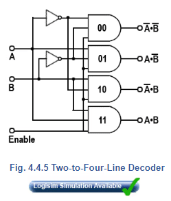
For example, a 2-to-4-line decoder is shown in Fig. 4.4.5, in this circuit the two input lines can be set to any one of four binary values, 00, 01, 10 or 11. Resulting from this input, and provided that the (active high) Enable input is set to logic 1, the output line corresponding to the binary value at inputs A and B changes to logic 1. The other output lines remain at logic 0.
When the binary value at inputs A and B changes, the logic 1 on the output changes to a different line as appropriate. If the enable input is set to logic 0, all the outputs remain at logic 0 whatever values appear at inputs A and B.
To obtain a logic 1 at any of the four outputs, the appropriate 3 input AND gate must have all of its inputs at logic 1. Provided that the Enable input is at logic 1, the output is controlled by using NOT gates to invert the logic applied from inputs A and B as required.
For example if inputs A and B are both at logic 0, the NOT gates at the inputs to the top (00) AND gate, invert both 0 inputs to logic 1, and therefore logic 1 appears at the 00 output. The 01 and 10 AND gates each have one input directly connected to the A or B input, whilst the other input is inverted.
The 11 gate has both A and B inputs directly connected to the AND gate so that 112 applied to A and B results in logic 1 at the 11 output.
Notice the similarity between Fig 4.4.5 and the 4-to-1-Line Multiplexer shown in Fig 4.2.4. In fact Fig. 4.4.5 could act as a demultiplexer for Fig 4.2.4 if the A and B inputs are used as control lines, and the enable input of Fig 4.4.5 used as the single data input. This example of dual use explains why decoders are often called Decoder/Demultiplexers. The circuit operation of Fig. 4.4.5 is shown in truth table form in Table 4.4.2, and a Logisim Simulation of Fig. 4.2.4 and Fig. 4.4.5 working together as a Multiplexer/Demultiplexer pair can be downloded from our Logisim page
74 Series Decoder ICs
2-to-4-line decoders (also called 1 of 4 decoders) are commercially available in both HC and HCT types in a number of versions from different manufacturers. These are typically dual packages such as the 74HC139 from NXP with two decoders per chip. One difference, (commonly used) from the basic example shown in Fig. 4.4.5 is that the outputs, and sometimes also the inputs, on such ICs may be ‘active low’ meaning that the active or logic 1 state is at the lower voltage of the two possible logic states, so that the output is sinking current when it is ‘logic 1’. This provides a greater drive capability than would be available if logic 1 was at its high voltage, and sourcing current.
Also, decoder ICs are very often used to activate the Enable or Chip Select inputs of other ICs, which are usually active low, so having a decoder with an active low output saves using extra inverter gates.
Another feature found in 74 series ICs is the common presence of buffer gates (which may be inverting or non-inverting) at the IC inputs and outputs to give improved input and output capabilities Clamp diodes and current limiting resistors are also often incuded at the inputs and outputs to give improved protection from high electrostatic external voltages.
|
135 videos|181 docs|71 tests
|
FAQs on Priority Encoders - Analog and Digital Electronics - Electrical Engineering (EE)
| 1. What is a priority encoder and what is its function? |  |
| 2. How does a priority encoder work? |  |
| 3. What is the advantage of using a priority encoder? |  |
| 4. Can a priority encoder handle multiple inputs with the same priority? |  |
| 5. How is a priority encoder different from a regular encoder? |  |


