Response of AC Circuits | Network Theory (Electric Circuits) - Electrical Engineering (EE) PDF Download

Finding the Response of Series RL Circuit
Consider the following series RL circuit diagram.
Response of AC Circuits | Network Theory (Electric Circuits) - Electrical Engineering (EE)
In the above circuit, the switch was kept open up to t = 0 and it was closed at t = 0. So, the AC voltage source having a peak voltage of Vm volts is not connected to the series RL circuit up to this instant. Therefore, there is no initial current flows through the inductor.
The circuit diagram, when the switch is in closed position, is shown in the following figure.
Response of AC Circuits | Network Theory (Electric Circuits) - Electrical Engineering (EE)
Now, the current i(t) flows in the entire circuit, since the AC voltage source having a peak voltage of Vm volts is connected to the series RL circuit.
We know that the current i(t) flowing through the above circuit will have two terms, one that represents the transient part and other term represents the steady state.
Mathematically, it can be represented as
i(t) = iTr(t)+iss(t)   Equation 1
Where,

  • iTr(t) is the transient response of the current flowing through the circuit.
  • iss(t) is the steady state response of the current flowing through the circuit.

In the previous chapter, we got the transient response of the current flowing through the series RL circuit. It is in the form of Response of AC Circuits | Network Theory (Electric Circuits) - Electrical Engineering (EE)
Substitute Response of AC Circuits | Network Theory (Electric Circuits) - Electrical Engineering (EE) in Equation 1.
Response of AC Circuits | Network Theory (Electric Circuits) - Electrical Engineering (EE)

Calculation of Steady State Current
If a sinusoidal signal is applied as an input to a Linear electric circuit, then it produces a steady state output, which is also a sinusoidal signal. Both the input and output sinusoidal signals will be having the same frequency, but different amplitudes and phase angles.
We can calculate the steady state response of an electric circuit, when it is excited by a sinusoidal voltage source using Laplace Transform approach.
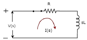
The s-domain circuit diagram, when the switch is in closed position, is shown in the following figure.
Response of AC Circuits | Network Theory (Electric Circuits) - Electrical Engineering (EE)
In the above circuit, all the quantities and parameters are represented in s-domain. These are the Laplace transforms of time-domain quantities and parameters.
The Transfer function of the above circuit is
Response of AC Circuits | Network Theory (Electric Circuits) - Electrical Engineering (EE)
Substitute s = jω in the above equation.
Response of AC Circuits | Network Theory (Electric Circuits) - Electrical Engineering (EE)
Magnitude of H(jω) is
Response of AC Circuits | Network Theory (Electric Circuits) - Electrical Engineering (EE)
Phase angle of H(jω) is
Response of AC Circuits | Network Theory (Electric Circuits) - Electrical Engineering (EE)
We will get the steady state current iss(t) by doing the following two steps −

  • Multiply the peak voltage of input sinusoidal voltage and the magnitude of H(jω).
  • Add the phase angles of input sinusoidal voltage and H(jω).

The steady state current iss(t) will be
Response of AC Circuits | Network Theory (Electric Circuits) - Electrical Engineering (EE)
Substitute the value of iss(t) in Equation 2.
Response of AC Circuits | Network Theory (Electric Circuits) - Electrical Engineering (EE)
We know that there is no initial current in the circuit. Hence, substitute t = 0 & i(t) = 0 in Equation 3 in order to find the value of constant, K.
Response of AC Circuits | Network Theory (Electric Circuits) - Electrical Engineering (EE)
Substitute the value of K in Equation 3.
Response of AC Circuits | Network Theory (Electric Circuits) - Electrical Engineering (EE)
Equation 4 represents the current flowing through the series RL circuit, when it is excited by a sinusoidal voltage source. It is having two terms. The first and second terms represent the transient response and steady state response of the current respectively.
We can neglect the first term of Equation 4 because its value will be very much less than one. So, the resultant current flowing through the circuit will be
Response of AC Circuits | Network Theory (Electric Circuits) - Electrical Engineering (EE)
It contains only the steady state term. Hence, we can find only the steady state response of AC circuits and neglect transient response of it.

The document Response of AC Circuits | Network Theory (Electric Circuits) - Electrical Engineering (EE) is a part of the Electrical Engineering (EE) Course Network Theory (Electric Circuits).
All you need of Electrical Engineering (EE) at this link: Electrical Engineering (EE)
68 videos|85 docs|62 tests

Top Courses for Electrical Engineering (EE)

FAQs on Response of AC Circuits - Network Theory (Electric Circuits) - Electrical Engineering (EE)

1. What is an AC circuit?
Ans. An AC circuit refers to an electrical circuit that operates on an alternating current. In this type of circuit, the direction of current periodically changes, typically following a sine wave pattern. AC circuits are commonly used in residential and commercial buildings, as well as in power transmission systems.
2. How does an AC circuit differ from a DC circuit?
Ans. The main difference between an AC circuit and a DC circuit is the direction of current flow. In an AC circuit, the current changes direction periodically, whereas in a DC circuit, the current flows in only one direction. Additionally, AC circuits typically use transformers for voltage conversion and transmission, while DC circuits rely on rectifiers and converters.
3. What are the advantages of AC circuits?
Ans. AC circuits have several advantages over DC circuits. Firstly, AC power can be easily converted to different voltage levels using transformers, allowing for efficient power transmission over long distances. Secondly, AC power can be easily generated using alternators, which are simpler and more reliable compared to DC generators. Lastly, AC circuits are safer to work with as the current periodically crosses zero, reducing the risk of electrocution.
4. What is the significance of impedance in AC circuits?
Ans. Impedance is a crucial aspect of AC circuits as it represents the total opposition to the flow of current, similar to resistance in DC circuits. Impedance is a complex quantity that consists of resistance and reactance, which is the opposition to current flow caused by inductance and capacitance. Understanding and managing impedance is essential for designing and analyzing AC circuits, as it affects the overall performance and power consumption.
5. How does the frequency of an AC circuit affect its behavior?
Ans. The frequency of an AC circuit refers to the number of complete cycles the alternating current completes per second, measured in Hertz (Hz). The frequency significantly impacts the behavior of an AC circuit. Higher frequencies result in higher energy transfer rates, while lower frequencies are suitable for power transmission over long distances. Additionally, the frequency affects the reactance of inductive and capacitive elements in the circuit, influencing the overall impedance and power factor.
68 videos|85 docs|62 tests
Download as PDF
Explore Courses for Electrical Engineering (EE) exam

Top Courses for Electrical Engineering (EE)

Signup for Free!
Signup to see your scores go up within 7 days! Learn & Practice with 1000+ FREE Notes, Videos & Tests.
10M+ students study on EduRev
Related Searches

Exam

,

study material

,

mock tests for examination

,

ppt

,

Free

,

video lectures

,

Summary

,

Sample Paper

,

shortcuts and tricks

,

Extra Questions

,

Objective type Questions

,

Semester Notes

,

MCQs

,

Response of AC Circuits | Network Theory (Electric Circuits) - Electrical Engineering (EE)

,

Important questions

,

past year papers

,

Response of AC Circuits | Network Theory (Electric Circuits) - Electrical Engineering (EE)

,

Response of AC Circuits | Network Theory (Electric Circuits) - Electrical Engineering (EE)

,

practice quizzes

,

Viva Questions

,

pdf

,

Previous Year Questions with Solutions

;