Single Phase Full Wave Bridge Rectifier | Power Electronics - Electrical Engineering (EE) PDF Download

Full Wave Bridge Rectifier
As shown in the given diagram of full wave bridge rectifier it consists of four diodes under the condition in which four diodes are connected the called bridge circuit. So due to this type of circuit is named bridge rectifier. A resistor is connected in the circuit where rectified output voltage appears called load resistor RL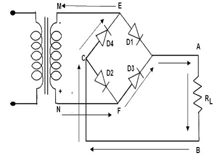 Bridge Rectifier Current Path Negative Cycle
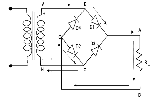 Bridge Rectifier Current Path Positive Cycle
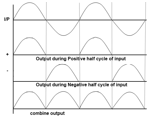 Bridge Rectifier Output Waveform
Working of Bridge Rectifier
- During the positive input half cycle terminal M of the secondary is positive and N is negative. Diode D1 and D3 becomes forward biased whereas D2 and D4 are reversed bias. Hence the current flows along point M, E, A, B, C, F and N producing a drop across RL.
- During the negative input half cycle secondary terminal N becomes positive and M is negative. Now D2 and D4 are forward bias and D1 and D3 are reversed bias. Now the current flows along points N, E, A, B, C, F and M. Hence we find that current keeps flowing through load resistance RL in the same direction (A, B). during both half cycles of the AC input the point A of the bridge rectifier always acts as an anode and point C as cathode. It frequency is twice that of supply frequency.
With A Resistive Load
- Full-wave rectification can also be obtained by using a bridge rectifier like the one shown in Figure 1. This full-wave bridge rectifier uses four diodes. During the positive half-cycle of the source voltage (Figure), diodes D2 and D3 are forward biased and can therefore be replaced by a closed switch. The load current flow during this period is through D2 and the load R and then through D3 and back to the source. This causes a positive drop across R.
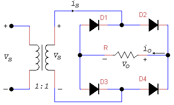 Full-wave Bridge Rectifier Circuit
 - Figure shows the full-wave bridge circuit during the negative half-cycle of the source voltage. Now diodes D1 and D4 are forward-biased and can therefore be replaced by closed switches. The load current path is now through D4, through R, and then through D1 to the source. The current path through R is in the same direction as before, so there is positive drop across R during both half-cycle. Thus, the full-wave bridge rectifier causes the load current to flow during both half-cycles. Figure shows the appropriate waveforms.
- The average and RMS values of voltage and current are like those for the full-wave center-tap case. However, the waveform of the voltage across the diode in Figure 3 shows that each diode must withstand a reverse voltage equal to Vm only.
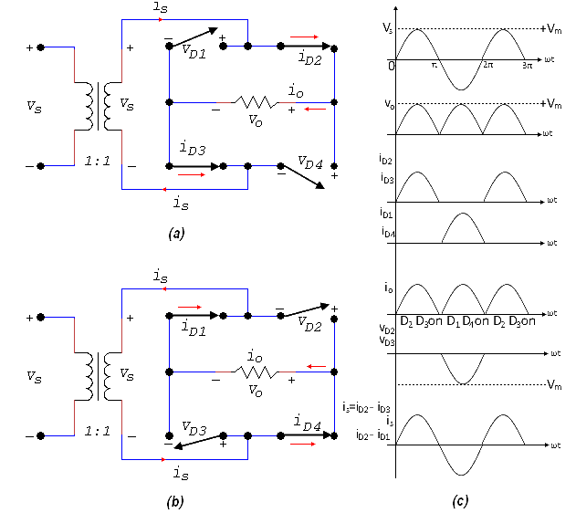 Full-wave Bridge Rectifier (a) Positive half-cycle (b) Negative half-cycle (c) Waveform
PIV rating for diodes ≥ Vm
Because there are two paths for the load current, the average diode current is just half of the average load current: ID(avg) = I(avg)/2
Example 1: The full-wave bridge rectifier of 5.7 is supported by a 120 V source. If the load resistance is 10.8 Ω, find
(i) The peak load voltage
(ii) The DC voltage across the load
(iii) The DC load current
(iv) The average current in each diode
(v) The average output power
(vi) The rectifier efficiency
(vii) The ripple factor
(viii) The power factor
(i) Peak load voltage
- Vm = √2 VRMS = (1.414) (120) = 170 V
(ii) DC voltage across the load
- Vo(avg) = 0.636 x 170 = 108 V
(iii) DC load current
- Io(avg) = 108 / 10.8 = 10 A
(iv) Average current in each diode since the diodes carry the load current alternative half-cycle
- ID(avg) = Io(avg) / 2 = 10 / 2 = 5 A
(v) Average output power
- Po(avg) = Vo(avg) x Io(avg) = 108 x 10 = 1080 W
(vi) Rectifier efficiency
- η = 8 / π2 = 0.81 or 81%
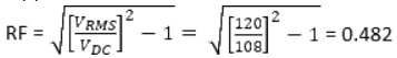
(vii) Ripple factor
(viii) Power factor
- PF = P/S = (Vo(avg) x Io(avg)) / (VRMS x IRMS) = (108 x 10) / (120 x 10) = 0.9
With Inductive (RL) Load
- Adding an inductance in series with the load resistance changes the voltage and current waveform. Figure 3 shows a bridge rectifier with an inductive load. Let us assume the inductance L to be approximately equal to R. the load current no longer consists of half sine waves, but the average current is still the same as given by equation
Io(avg) = 2lm / π = 2Vm / πR - The AC line current is no longer sinusoidal but is approximately a square wave Figure 4 show the voltage and current waveforms.
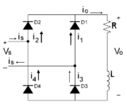
Full-wave Bridge Rectifier with Inductive Load
- If we increase the load inductance until it is much larger than R, the ripple across the load becomes small. If we assume an infinite load inductance, the load current becomes constant and the circuit behavior is as shown by the waveforms in Figure 4(b). Diodes D2 and D3 conduct a constant load current on the positive half-cycle, while diodes D1 and D4 do the same on the negative half-cycle.
- The source current is given by:
is = i3 – i1 = i2 – i4 - although not a sine wave, the AC source current is an alternating waveform of rectangular shape. The load is always connected to the source, but the connection is reversed on alternate half-cycles.
- The output voltage (Vo) is a full-wave rectified waveform. Its average value can be determined from
- Vo(avg) = VL(avg) + VR(avg)
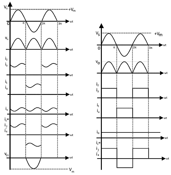
Full-wave Bridge Rectifier with Inductive Load (a) Waveforms for (L = R) (b) Waveform for (L >> R)
- Where VR is the voltage across the resistor and VL is the induced voltage across the inductance. In periodic operation, VL(avg). the average voltage across an inductor, must be zero. Therefore
VR(avg) = Vo(avg) = (2 Vm) / π
= 0.636 Vm - The average load voltage is the same as for the resistive case. The average load current can be determined from
Io(avg) = VR(avg) / R
= 0.636 (Vm / R) - Since the load current now is essentially constant, its RMS, maximum, and average values are the same.
IRMS = Io(avg) - Since diodes in the bridge conduct on alternate half-cycles, the average current in each diode is
ID(avg) = Io(avg) / 2 - And the RMS current in each diode is
ID(RMS) = Io(avg) / √ 2
Example 2: A full-wave bridge rectifier with an RL load is connected to a 120 V source the load resistance is 10 Ω and L >> R, find
(i) The average load voltage
(ii) The average load current
(iii) The maximum load current
(iv) The RMS value of load current
(v) The average current in each diode
(vi) The RMS current in each diode
(vii) The power supplied to the load
The peak load voltage is
- Vm = √ 2 VRMS = (1.414) (120) = 170 V
(i) Average load voltage- Vo(avg) = 0.636 x 170 = 108 V
(ii) Average load current
- Vo(avg) / R = 108 / 10 = 10.8 A
(iii) Maximum load current = average load current = 10.8 A
(iv) RMS value of load current = average load current = 10.8 A
(v) Average current in each diode
- ID(avg) = Io(avg) / 2 = 10.8 / 2 = 10.8 /2 = 5.4 A
(vi) RMS current in each diode
- ID(RMS) = Io(avg) / √2 = 10.8 / √2 = 7.6 A
(vii) Power supplied to the load
- I2RMS R = 10.82 x 10 = 1167 W
|
5 videos|73 docs|46 tests
|


Previous Year Questions with Solutions
,mock tests for examination
,video lectures
,Exam
,Summary
,ppt
,Single Phase Full Wave Bridge Rectifier | Power Electronics - Electrical Engineering (EE)
,Viva Questions
,Important questions
,Extra Questions
,shortcuts and tricks
,past year papers
,Free
,Single Phase Full Wave Bridge Rectifier | Power Electronics - Electrical Engineering (EE)
,Objective type Questions
,practice quizzes
,MCQs
,Single Phase Full Wave Bridge Rectifier | Power Electronics - Electrical Engineering (EE)
,Semester Notes
,study material
,Sample Paper
;


Single Phase Full Wave Bridge Rectifier Free PDF Download
Importance of Single Phase Full Wave Bridge Rectifier
Single Phase Full Wave Bridge Rectifier Notes
Single Phase Full Wave Bridge Rectifier Electrical Engineering (EE) Questions
Study Single Phase Full Wave Bridge Rectifier on the App
|
© EduRev
|
Education Revolution
|


|


