Study Notes For Synchronous Machines - 2 | Electrical Engineering SSC JE (Technical) - Electrical Engineering (EE) PDF Download
Cylindrical Rotor Synchronous Generator
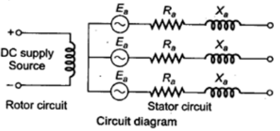
The alternator is operating on no load i.e., the rotor is rotating and energized and the stator is open-circuited.
- Its circuit diagram is shown in below.
- An equivalent circuit of a synchronous generator shown in below.
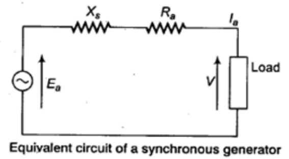
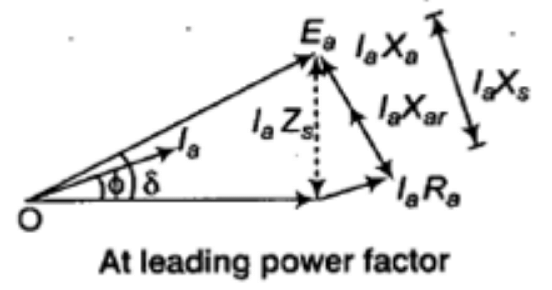
- Let Xs = Synchronous reactance, Xar = Fictitious reactance, Xa = Armature reactance, Ra = Armature resistance, and Zs = Synchronous impedance.
Xs = Xar + Xa
Zs = Ra + j Xs
Ea = V + Ia Zs
Phasor Diagram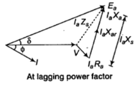
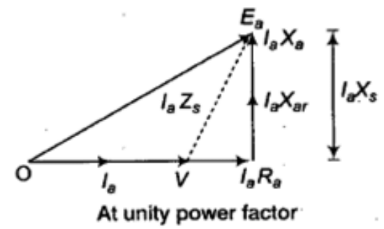
- The phasor diagram for inductive, purely resistive and capacitive loads are shown in the figure below. All these phasor diagrams apply to one phase of a 3-φ machine.
- At lagging, power factor:

- At unity, power factor:

- At leading, power factor:

Power Relationship
- Mechanical power input to the generator Pmechanical = Tsωs
- DC power input to a wound rotor Pin electrical = If
- Total power input: Pin = Tsωs + If
- Real power output:

- Reactive power output:

where, V = Terminal voltage per phase, and Ef = Excitation voltage per phase = Phase angle between Ef and V, and Xs = Synchronous reactance
Salient Pole Synchronous Machine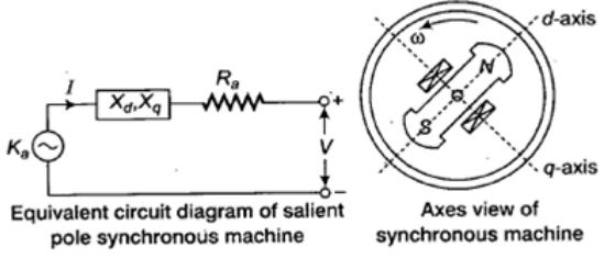
The component currents Id and Iq provide component voltage drops jId Xd and jId Xq as shown in the figure.
Ea = V + IaRa + jIdXd + jIqXq
I = Id + Iq
If Ra is neglected, Ea = V + jIdXd + jIqXd
- Phasor Diagram
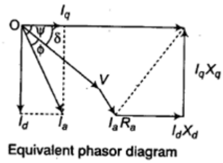
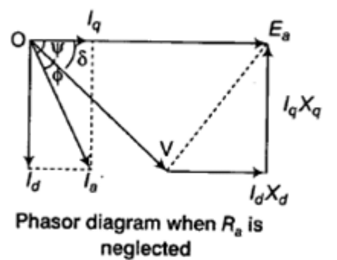
- For Generating Mode:

- For Motoring Mode:

Note: δ = ψ – φ (generating mode), and δ = φ – ψ (motoring mode)
- Power Angle

Use + for synchronous generator, and - for synchronous motor (here Ra is neglected)
- Output Power
P0 = 3V(Id sin δ + Id cos δ)
- Total Power Developed

Cylindrical Rotor Synchronous Motor
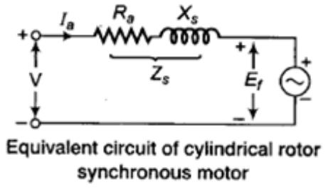
where, V = Terminal phase voltage applied to the armature, Ef = Excitation voltage, Ra = Effective armature resistance/phase, Xs = Synchronous reactance/phase, Zs = Impedance/phase.
Ea = V – IaRa – jIaXs
- Phasor Diagram

Salient Pole Synchronous Motor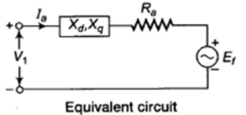
Ea = V – IaRa – jIaXq – jId(Xd – Xq)
- Phasor Diagram:
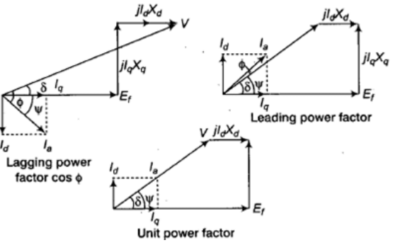
- Power Developed:

Experimental Determination of Circuit Parameters
In the per phase equivalent circuit model illustrated above first for Generator & Second For Motor, there are three parameters need to be determined: winding resistance Ra, synchronous reactance Xs, and induced emf in the phase winding Ea. The phase winding resistance Ra can be determined by measuring DC resistance of the winding using the volt-ampere method, while the synchronous reactance and the induced emf can be determined by the open circuit and short circuit tests.
Open Circuit Test
Drive the synchronous machine at the synchronous speed using a prime mover when the stator windings are open circuited. Vary the rotor winding current, and measure stator winding terminal voltage. The relationship between the stator winding terminal voltage and the rotor field current obtained by the open circuit test is known as the open circuit characteristic of the synchronous machine.
Short Circuit Test
Reduce the field current to a minimum, by using the field rheostat, and then open the field supply circuit breaker. Short the stator terminals of the machine together through three ammeters; Close the field circuit breaker; and raise the field current to the value noted in the open circuit test at which the open circuit terminal voltage equals the rated voltage while maintaining the synchronous speed. Record the three stator currents. (This test should be executed quickly as the stator currents may be greater than the rated value).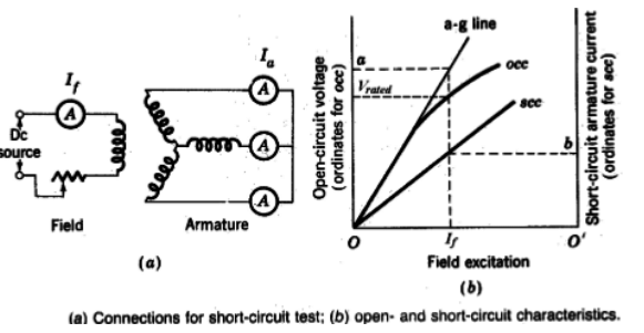
- Under the assumptions that the synchronous reactance Xs and the induced emf Ea have the same values in both the open and short circuit tests, and that Xs >> Ra, we have

Effect of Excitation
By controlling the rotor excitation current such that the synchronous condenser draws a line current of leading phase angle, whose imaginary component cancels that of the load current, the total line current would have a minimum imaginary component.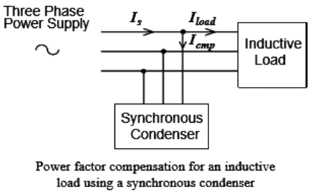
Therefore, the overall power factor of the inductive load and the synchronous condenser would be close to one and the magnitude of the overall line current would be the minimum.
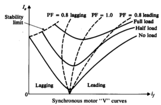
It can also be seen that only when the power factor is a unit or the stator current is aligned with the terminal voltage, the magnitude of the stator current is minimum.
By plotting the magnitude of the stator current against the rotor excitation current, a family of “V” curves can be obtained. It is shown that a larger rotor field current is required for a larger active load to operate at unity power factor.
Voltage Regulation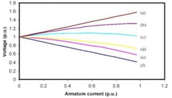
The variation in the terminal voltage with load is called voltage regulation, hence
Per-unit voltage regulation = (|VNL|-|VFL|)/|VFL| = |Ef|-|V|/|V|
- (a) zero power factor leading
- (b) 0.8 power factor leading
- (c) 0.9 power factor leading
- (d) unity power factor
- (e) 0.9 power factor lagging
- (f) zero power factor lagging.
|
23 videos|94 docs|42 tests
|


