Voltage Sources | Network Theory (Electric Circuits) - Electrical Engineering (EE) PDF Download
Introduction
- A Voltage Source is an active element that provides a specified and constant voltage which is completely independent of any other circuit elements. However, the rated voltage across the terminals of real or practical voltage sources drops off as the load current it supplies increases.
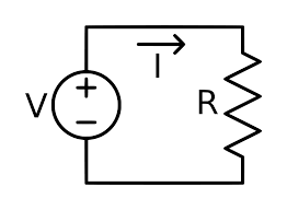
- There are two types of elements within an electrical or electronics circuit: passive elements and active elements. An active element is one that is capable of continuously supplying energy to a circuit, such as a battery, a generator, an operational amplifier, etc. A passive element on the other hand are physical elements such as resistors, capacitors, inductors, etc, which cannot generate electrical energy by themselves but only consume it.
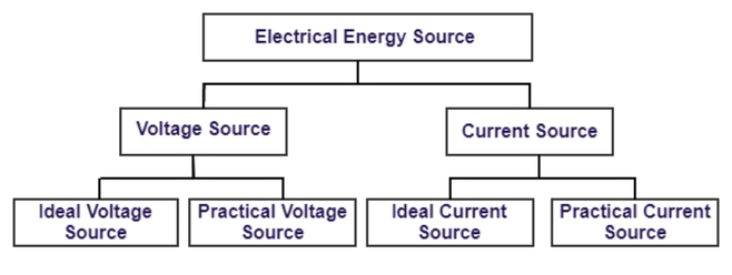
- The types of active circuit elements that are most important to us are those that supply electrical energy to the circuits or network connected to them. These are called electrical sources with the two types of electrical sources being the voltage source and the current source. The current source is usually less common in circuits than the voltage source, but both are used and can be regarded as complements of each other.
- An electrical supply or simply, a source, is a device that supplies electrical power to a circuit in the form of a voltage source or a current source. Both types of electrical sources can be classed as a direct (DC) or alternating (AC) source in which a constant voltage is called a DC voltage and one that varies sinusoidally with time is called an AC voltage. So for example, batteries are DC sources and the 230V wall socket or mains outlet in your home is an AC source.
- We said earlier that electrical sources supply energy, but one of the interesting characteristic of an electrical source, is that they are also capable of converting non-electrical energy into electrical energy and vice versa. For example, a battery converts chemical energy into electrical energy, while an electrical machine such as a DC generator or an AC alternator converts mechanical energy into electrical energy.
- Renewable technologies can convert energy from the sun, the wind, and waves into electrical or thermal energy. But as well as converting energy from one source to another, electrical sources can both deliver or absorb energy allowing it to flow in both directions.
- Another important characteristic of an electrical source and one which defines its operation, are its I-V characteristics. The I-V characteristic of an electrical source can give us a very nice pictorial description of the source, either as a voltage source and a current source as shown.
Electrical Sources
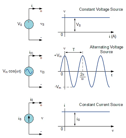
- Electrical sources, both as a voltage source or a current source can be classed as being either independent (ideal) or dependent, (controlled) that is whose value depends upon a voltage or current elsewhere within the circuit, which itself can be either constant or time-varying.
- When dealing with circuit laws and analysis, electrical sources are often viewed as being “ideal”, that is the source is ideal because it could theoretically deliver an infinite amount of energy without loss thereby having characteristics represented by a straight line. However, in real or practical sources there is always a resistance either connected in parallel for a current source, or series for a voltage source associated with the source affecting its output.
The Voltage Source
- A voltage source, such as a battery or generator, provides a potential difference (voltage) between two points within an electrical circuit allowing current to flowing around it. Remember that voltage can exist without current. A battery is the most common voltage source for a circuit with the voltage that appears across the positive and negative terminals of the source being called the terminal voltage.
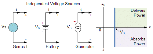
- An ideal voltage source is defined as a two terminal active element that is capable of supplying and maintaining the same voltage, (v) across its terminals regardless of the current, (i) flowing through it. In other words, ideal voltage sources will supply a constant voltage at all times regardless of the value of the current being supplied producing an I-V characteristic represented by a straight line.
- Then an ideal voltage source is known as an Independent Voltage Source as its voltage does not depend on either the value of the current flowing through the source or its direction but is determined solely by the value of the source alone. So for example, an automobile battery has a 12V terminal voltage that remains constant as long as the current through it does not become to high, delivering power to the car in one direction and absorbing power in the other direction as it charges.
- On the other hand, a Dependent Voltage Source or controlled voltage source, provides a voltage supply whose magnitude depends on either the voltage across or current flowing through some other circuit element. A dependent voltage source is indicated with a diamond shape and are used as equivalent electrical sources for many electronic devices, such as transistors and operational amplifiers.
Connecting Voltage Sources Together
- Ideal voltage sources can be connected together in both parallel or series the same as for any circuit element. Series voltages add together while parallel voltages have the same value. Note that unequal ideal sources cannot be connected directly together in parallel.

Voltage Source in Parallel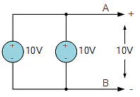
- While not best practice for circuit analysis, ideal voltage sources can be connected in parallel provided they are of the same voltage value. Here in this example, two 10 volt voltage source are combined to produce 10 volts between terminals A and B. Ideally, there would be just one single voltage source of 10 volts given between terminals A and B.
- What is not allowed or is not best practice, is connecting together ideal voltage sources that have different voltage values as shown, or are short-circuited by an external closed loop or branch.
Badly Connected Voltage Sources
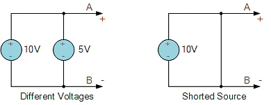
- However, when dealing with circuit analysis, voltage sources of different values can be used providing there are other circuit elements in between them to comply with Kirchoff’s Voltage Law, KVL.
- Unlike parallel connected sources, ideal voltage sources of different values can be connected together in series to form a single voltage source whose output will be the algebraic addition or subtraction of the voltages used. Their connection can be as: series-aiding or series-opposing voltages as shown.
Voltage Source in Series
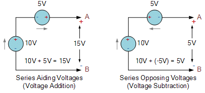
- Series aiding voltage sources are series connected sources with their polarities connected so that the plus terminal of one is connected to the negative terminal of the next allowing current to flow in the same direction. In the example above, the two voltages of 10V and 5V of the first circuit can be added, for a VS of 10 + 5 = 15V. So the voltage across terminals A and B is 15 volts.
- Series opposing voltage sources are series connected sources which have their polarities connected so that the plus terminal or the negative terminals are connected together as shown in the second circuit above. The net result is that the voltages are subtracted from each other. Then the two voltages of 10V and 5V of the second circuit are subtracted with the smaller voltage subtracted from the larger voltage. Resulting in a VS of 10 – 5 = 5V.
- The polarity across terminals A and B is determined by the larger polarity of the voltage sources, in this example terminal A is positive and terminal B is negative resulting in +5 volts. If the series-opposing voltages are equal, the net voltage across A and B will be zero as one voltage balances out the other. Also any currents (I) will also be zero, as without any voltage, current can not flow.
Voltage Source Example
Two series aiding ideal voltage sources of 6 volts and 9 volts respectively are connected together to supply a load resistance of 100 Ohms. Calculate: the source voltage, VS, the load current through the resistor, IR and the total power, P dissipated by the resistor. Draw the circuit.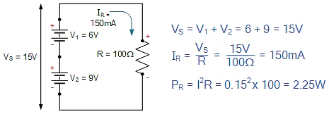
Thus, VS = 15V, IR = 150mA or 0.15A, and PR = 2.25W.
Practical Voltage Source
- We have seen that ideal voltage sources can provide a voltage supply that is independent of the current flowing through it, that is, it maintains the same voltage value always. This idea may work well for circuit analysis techniques, but in the real world voltage sources behave a little differently as for practical voltage sources, its terminal voltage will actually decrease with an increase in load current.
- As the terminal voltage of an ideal voltage source does not vary with increases in the load current, this implies that an ideal voltage source has zero internal resistance, RS = 0. In other words, it is a resistorless voltage source. In reality all voltage sources have a very small internal resistance which reduces their terminal voltage as they supply higher load currents.
- For non-ideal or practical voltage sources such as batteries, their internal resistance (RS) produces the same effect as a resistance connected in series with an ideal voltage source as these two series connected elements carry the same current as shown.
Ideal and Practical Voltage Source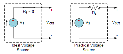
- You may have noticed that practical voltage sources closely resemble that of a Thevenin’s equivalent circuit as Thevenin’s theorem states that “any linear network containing resistances and sources of emf and current may be replaced by a single voltage source, VS in series with a single resistance, RS“. Note that if the series source resistance is low, the voltage source is ideal. When the source resistance is infinite, the voltage source is open-circuited.
- In the case of all real or practical voltage sources, this internal resistance, RS no matter how small has an effect on the I-V characteristic of the source as the terminal voltage falls off with an increase in load current. This is because the same load current flows through RS.
- Ohms law tells us that when a current, (i) flows through a resistance, a voltage drop is produce across the same resistance. The value of this voltage drop is given as i*RS. Then VOUT will equal the ideal voltage source, VS minus the i*RS voltage drop across the resistor. Remember that in the case of an ideal source voltage, RS is equal to zero as there is no internal resistance, therefore the terminal voltage is same as VS.
- Then the voltage sum around the loop given by Kirchoff’s voltage law, KVL is: VOUT = VS – i*RS. This equation can be plotted to give the I-V characteristics of the actual output voltage. It will give a straight line with a slope –RS which intersects the vertical voltage axis at the same point as VS when the current i = 0 as shown.
Practical Voltage Source Characteristics
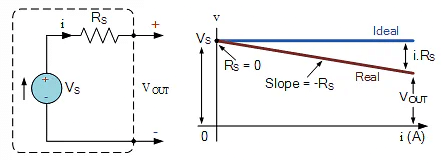
- Therefore, all ideal voltage sources will have a straight line I-V characteristic but non-ideal or real practical voltage sources will not but instead will have an I-V characteristic that is slightly angled down by an amount equal to i*RS where RS is the internal source resistance (or impedance). The I-V characteristics of a real battery provides a very close approximation of an ideal voltage source since the source resistance RS is usually quite small.
- The decrease in the angle of the slope of the I-V characteristics as the current increases is known as regulation. Voltage regulation is an important measure of the quality of a practical voltage source as it measures the variation in terminal voltage between no load, that is when IL = 0, (an open-circuit) and full load, that is when IL is at maximum, (a short-circuit).
Voltage Source Example
- A battery supply consists of an ideal voltage source in series with an internal resistor. The voltage and current measured at the terminals of the battery were found to be VOUT1 = 130V at 10A, and VOUT2 = 100V at 25A. Calculate the voltage rating of the ideal voltage source and the value of its internal resistance. Draw the I-V characteristics.
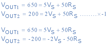
- Firstly lets define in simple “simultaneous equation form“, the two voltage and current outputs of the battery supply given as: VOUT1 and VOUT2.
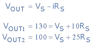
- As with have the voltages and currents in a simultaneous equation form, to find VS we will first multiply VOUT1 by five, (5) and VOUT2 by two, (2) as shown to make the value of the two currents, (i) the same for both equations.
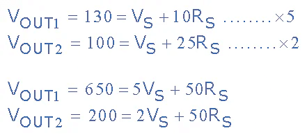
- Having made the co-efficients for RS the same by multiplying through with the previous constants, we now multiply the second equation VOUT2 by minus one, (-1) to allow for the subtraction of the two equations so that we can solve for VS as shown.
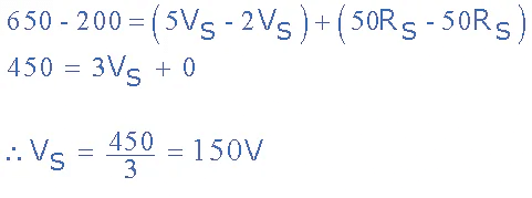
 Rearrange to give:
- Knowing that the ideal voltage source, VS is equal to 150 volts, we can use this value for equation VOUT1 (or VOUT2 if so wished) and solve to find the series resistance, RS.
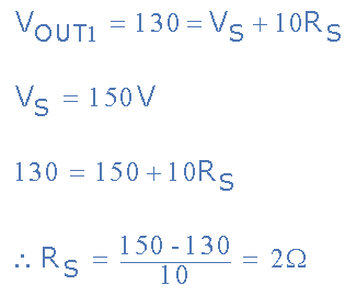
Then for our simple example, the batteries internal voltage source is calculated as: VS = 150 volts, and its internal resistance as: RS = 2Ω. The I-V characteristics of the battery are given as:
Battery I-V Characteristics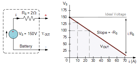
Dependent Voltage Source
- Unlike ideal voltage sources which produces a constant voltage across its terminals regardless of what is connected to it, a controlled or dependent voltage source changes its terminal voltage depending upon the voltage across, or the current through, some other element connected to the circuit, and as such it is sometimes difficult to specify the value of a dependent voltage source, unless you know the actual value of the voltage or current on which it depends.
- Dependent voltage sources behave similar to the electrical sources we have looked at so far, both practical and ideal (independent) the difference this time is that dependent voltage sources can be controlled by an input current or voltage. A voltage source that depends on a voltage input is generally referred to as a Voltage Controlled Voltage Source or VCVS. A voltage source that depends on a current input is referred too as a Current Controlled Voltage Source or CCVS.
- Ideal dependent sources are commonly used in the analysing the input/output characteristics or the gain of circuit elements such as operational amplifiers, transistors and integrated circuits. Generally, an ideal voltage dependent source, either voltage or current controlled is designated by a diamond-shaped symbol as shown.
Dependent Voltage Source Symbols
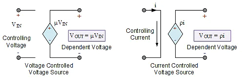
- Ideal dependent voltage-controlled voltage sources, VCVS, maintain an output voltage equal to some multiplying constant (basically an amplification factor) times the controlling voltage present elsewhere in the circuit. As the multiplying constant is, well, a constant, the controlling voltage, VIN will determine the magnitude of the output voltage, VOUT. In other words, the output voltage “depends” on the value of input voltage making it a dependent voltage source and in many ways, an ideal transformer can be thought of as a VCVS device with the amplification factor being its turns ratio.
- Then the VCVS output voltage is determined by the following equation: VOUT = μVIN. Note that the multiplying constant μ is dimensionless as it is purely a scaling factor because μ = VOUT/VIN, so its units will be volts/volts.
- An ideal dependent current-controlled voltage source, CCVS, maintains an output voltage equal to some multiplying constant (rho) times a controlling current input generated elsewhere within the connected circuit. Then the output voltage “depends” on the value of the input current, again making it a dependent voltage source.
- As a controlling current, IIN determines the magnitude of the output voltage, VOUT times the magnification constant ρ (rho), this allows us to model current-controlled voltage sources as a trans-resistance amplifier as the multiplying constant, ρ gives us the following equation: VOUT = ρIIN. This multiplying constant ρ (rho) has the units of Ohm’s because ρ = VOUT/IIN, and its units will therefore be volts/amperes.
Summary
- We have seen here that Voltage Sources can be either ideal independent voltage sources, or controlled dependent voltage sources. Independent voltage sources supply a constant voltage that does not depend on any other quantity within the circuit. Ideal independent sources can be batteries, DC generators or time-varying AC voltage supplies from alternators.
- Independent voltage sources can be modelled as either an ideal source, (RS = 0) where the output is constant for all load currents. Or a non-ideal or practical source, such as a battery with a resistance connected in series with the circuit to represent the internal resistance of the source. Ideal voltage sources can be connected together in parallel only if they are of the same voltage value. Series-aiding or series-opposing connections will affect the output value.
- Also for solving circuit analysis and complex theorems, voltage sources become short-circuited sources making their voltage equal to zero to help solve the network. Note also that voltage sources are capable of both delivering or absorbing power.
- Ideal dependent voltage sources represented by a diamond-shaped symbol, are dependent on, and are proportional too an external controlling voltage or current. The multiplying constant, μ for a VCVS has no units, while the multiplying constant ρ for a CCVS has units of Ohm’s. A dependent voltage source is of great interest to model electronic devices or active devices such as operational amplifiers and transistors that have gain.
|
73 videos|139 docs|62 tests
|
FAQs on Voltage Sources - Network Theory (Electric Circuits) - Electrical Engineering (EE)
| 1. What is the purpose of a voltage source in an electrical circuit? |  |
| 2. How do you connect multiple voltage sources together in a circuit? |  |
| 3. What are the consequences of badly connecting voltage sources in a circuit? |  |
| 4. What are the characteristics of a practical voltage source? |  |
| 5. Can you give an example of a dependent voltage source? |  |


