Modeling Of Single Phase Transformers | Electrical Machines - Electrical Engineering (EE) PDF Download

Modeling of Single Phase Transformers
In the last lecture, we have shown how to relax two of the assumptions that we made regarding an idea transformer that is of lossless winding, and no leakage.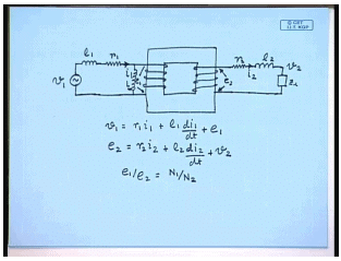
And we found that a practical transformer more rule can be derived from an ideal transformer which is represented by a core and two windings incorporating the resistance of the windings, and the effect of leakage flux can be incorporated by assuming in leakage inductance in series with both the windings r 1, r 2, l 1, l 2, v 1; the load you usually connect be connected here equal to this v 2. Current flowing in coil one is i 1, flowing in coil 2 is i 2; the induced voltage occurs coil one is e 1 while the induced voltage occurs coil 2 is v 2. Then we have seen v 1 equal to r 1 i 1 plus l 1 d i 1 d t plus e 1, and e 2 equal to r 2 i 2 plus l 2 d i 2 d t plus v 2, and as in the case of an ideal transformer e 1 by e 2 equal to N 1 by N 2.
However this still does not take into account the magnetization current; that is the current to be drawn by a practical transformer even when i 2 is 0. This can be easily incorporated by assuming a magnetization inductance across the coil l l. This is so because the induced voltage e 1 leads the flux by 90 degree. So, an inductance connected across e 1 the current flossing through the inductance connected across e 1 will lag e 1 by 90 degree and will be in phase with the core flux phi m which is responsible for generating the core flux phi m. So, the effect of finite permeability of a practical single phase transformer is taken care of by considering a magnetizing inductance across the winding and leakage inductance in series with the winding.
The last detail that needs to be incorporated in the model of a single phase transformer is the core losses. It is well known that when a ferromagnetic martial is subjected to an alternating flux then two type of losses occur; one is the hysteresis loss, another is the eddy current loss. Both of them increase with increase in the flux density and the frequency of the alternative current waveform; although, these relations are not always linear for the hysteresis loss the loss is proportional power loss is proportional to the frequency, however not for the eddy current loss.
But in a normal application of a transformer normally the supply frequency and the voltage will be constant; therefore, for a given application there will not be variation with frequency since the frequency is constant. These losses can be approximated by losses occurring in some resistances fictitious resistances that are connected across the coil; therefore, in order to represent the losses that occur in a practical transformer some core loss resistance is connected across the coil that is parallel to the magnetization branch. Therefore the complete model or a practical transformer incorporating an ideal transformer looks as follows.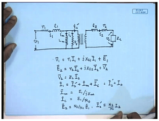
First just put the winding resistance of coil one, then the leakage inductance of coil one and then the coil one of the ideal transformer. In order to take care of the finite magnetization current we connect a magnetization inductance and to care of the core loss we connect a core loss resistance. This is the ideal transformer. The secondary side similarly there will be a leakage inductance l 2 and the winding resistance r 2. The applied voltage in the primary side is v 1, current through the primary is i 1, the magnetization current is i m, the core loss component of the current i c together they are called the no load current i 0.
The current flowing through the ideal transformer is the reflection of the load current i 2 dash, and the current in the load circuit is i 2, load voltage be v 2. This is the complete model of a practical single phase transformer taking into account the non idealities which also incorporates an ideal transformer. In phasor form the equations can be written as v 1 equal to r 1 I 1 plus j x l 1 I 1 plus E 1, and E 2 equal to r 2 I 2 plus j x l 2 I 2 plus v 2. V 2 equal to Z L I 2; I 1 equal to I 2 dash plus I n plus I c equal to I 2 dash plus I 0. I m equal to E 1 by j x m, I c equal to E 1 by R 0; E 2 equal to N 2 by N 1 E 1, and I 2 dash equal to N 2 by N 1 I 2. This set of equation defines the complete steady state model of a practical single phase transformer. Normally the steady state phasor relationships are described by a phasor diagram. Hence it will be interesting to draw the phasor diagram of a single phase transformer which is shown next.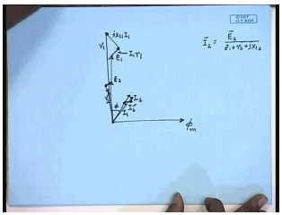
Again we draw the phasor diagram taking the core flux phi m to be the reference phasor. Both E1 and E 2 will lead I n by 90 degree. Then the current I 2 is given by which will lag assume to lag E 2 by an angle phi. The phasor i 2 dash will be in phase with I 2 and will be in fact a scaled version of I 2. The current I 1 can be obtained phasor sum of I 2 dashed with I m which is in phase with phi m and I c which is in phase with E 1 which gives me the phasor I 1. The voltage v 1 can be obtained on the first equation E 1 plus I 1 r 1 plus j x L 1 i 1, this is I 1 r 1. So, this is the phasor v 1; similarly, phasor v 2 can be obtained by from the second equation it is E 2 minus I 2 r 2 minus j x L 2 I 2 which can be used for solving any problem related to single phase transformer.
However, if we take a closer look at the circuit model of the single phase transformer that we have so derived, we will find that this is not very suitable for applying the known circuit analysis techniques since there is an ideal transformer between the two parts. Hence we cannot apply for example a kcl or kvl where the loop current is expected to flow across the ideal transformer. This path we cannot write a loop equation involving a path like this since we do not know the voltage drop across the ideal transformer; therefore, it will be more convenient if we can eliminate this ideal transformer.
This is done by referring the secondary of the ideal transformer to the primary or vice versa; the primary can also be referred to the secondary let us see the first option. By referring we mean we connect an equivalent circuit across the terminals of the ideal transformers so that the current drawn by the equivalent circuit is the same i 2 dust as it is drawn by the ideal transformer. Let us see what should be that circuit.
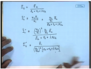
The current I 2 is given by E 2 divided by Z L plus r 2 plus j x l 2 and I 2 dash equal to N 2 I 2 by N 1; therefore, I 2 dash equal to N 2 by N 1 E 2 divided by Z L plus r 2 plus j x l, 2 or I can write I 2 dash to be N 2 by N 1 square into N 1 by N 2 E 2 divided by Z L plus r 2 plus j X l 2, but N 1 by N 2 E 2 is equal to E 1. Therefore I 2 dash equal to E 1 divided by N 1 by N 2 square into Z L plus r 2 plus j X l 2. Now let us have a look at the model circuit model that we have obtained. The voltage across these two terminals is E 1 and the current drawn from these terminals is I 2 dash. Now the same current I 2 dash will flow provided an impendence of this form is connected across this terminals; therefore, we can replace the ideal transformer and the secondary circuit after that by an equivalent impendence given by this formula.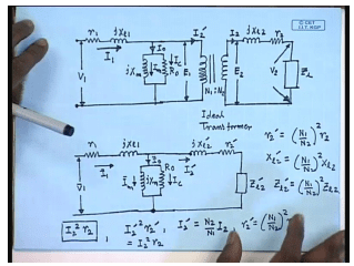
Hence the original circuit model I 0 I 1 I 0 I m I c I 2 dash I 2 and v 2. This was the original circuit model of the practical single phase transformer which incorporated an ideal transformer with primary turns N 1 and secondary turns N 2. This circuit model in argue can be replaced by an equivalent circuit model where up to this point there is no change, but the rest of the circuit is replaced by an equivalent circuit where the elements are given by, so that the current drawn from this branch is I 2 dash as in the case of the original model. The required equivalent impedances are related to the actual impendence’s as follows; r 2 dash equal to N 1 by N 2 whole square r 2 X l 2 dash equal to N 1 by N 2 square X l 2 and Z l 2 dash equal to N 1 by N 2 square Z l 2.
That dashed quantities are called the referred impendence of the secondary side referred to the primary side, and the equivalent circuit thus obtained is called the exact equivalent circuit of a single phase transformer referred to the primary side; that is the side with suffix 1 and number of turns N 1. Now let us see the actual secondary current to us I 2. The power loss in the resistance was I 2 square r 2. This was the actual power loss in the secondary circuit; in the equivalent circuit the power loss is I 2 dash square r 2 dash but i 2 dash itself is equal to N 2 by N 1 I 2, and r 2 dash equal to N 1 by N 2 square r 2. Therefore, I 2 dash square r 2 dash is same as I 2 square r 2; therefore, we see that the power consumed by the secondary resistance is not changed by referring this circuit. So, it preservers the power relations; what will be the referred secondary voltage v 2 dash? We call this v 2 dash.
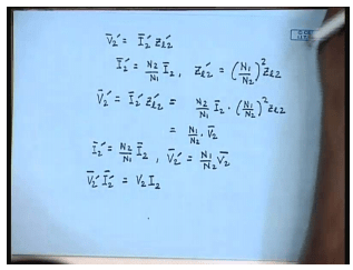
When v 2 dash equal to I 2 dash Z l 2 dash, but I 2 dash equal to N 2 by N 1 I 2, and Z l 2 dash equal to N 1 by N 2 whole square Z l 2. Therefore, v 2 dash equal to I 2 dash Z l 2 dash is equal to N 2 by N 1 I 2 into N 1 by N 2 whole square Z l 2 equal to N 1 by N 2 v 2. So, we have I 2 dash equal to N 2 by N 1 into I 2 and v 2 dash equal to N 1 by N 2 into v 2; therefore, v 2 dash I 2 dash equal to v 2 I 2. So, the kvl consumed by the referred circuit referred load circuit is same as the kvl consumed by the original load circuit. So, you have seen that the load circuit can be referred to the source side by multiplying the load side parameters values that is the impendence’s by the trans ratio square. Similar thing can be done for the source side; that is instead of referring the rest of the circuit across this terminal it is possible to refer the left of the circuit across this terminal; in which case the secondary side impendence’s voltages and current will remain same while the impendence’s of the primary side will change.
Let us see what will be the relations. The actual circuit model which is given by this diagram, we now want to replace with by an equivalent circuit with an equivalent network connected across this two terminal. This circuit which is also an equivalent circuit referred to the primary side was obtained by replacing the right hand side of the circuit after this point by an equivalent impendence, and this circuit was called the exact equivalent circuit of the transformer referred to the primary side since the impendence on the secondary side where referred by the turns ratio. Now we want to derive an equivalent circuit of the transformer referred to the secondary side where the secondary impendence’s will remain as it is; however, the primary source and impendence will be referred to the secondary side. Although it is possible to connect different types of impendence’s we would like to detail the structure or the topology of the circuit on the primary side as far as possible; therefore, we assume the equivalent circuit to be as follows.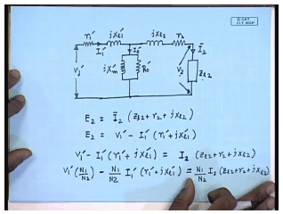
The secondary side does not change. We would like to retain the structure of the primary circuit; therefore, you will have an equivalent impendence in series equivalent inductance in series and call it j X l 1 dash. The shunt branch consisting of a shunt reactor j X m dash and r 0 dash and a series resistance r 1 dash connected to a source v 1 dash. Our objective is to find out an expression of the dashed quantity so that when the dashed quantities are applied to the circuit the secondary current remain I 2, and the secondary voltage becomes v 2 when the load connected is Z l 2. Let this current be I 1 dash, the voltage E 2 equal to I 2 into also E 2 equal to; therefore, multiplying both sides by N 1 by N 2 we can write this.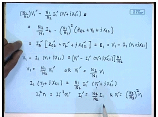
Or it can be written as but N 2 I 2 divided by N 1 equal to I 2 dash and N 1 by N 2 square into this impendence’s are. However from our previous discussion we have seen that this quantity I 2 dash into Z l 2 dash into r 2 dash plus j X l 2 dash this is equal to E 1 and is given by v 1 minus i 1 r 1 plus j X l 1. Therefore, v 1 minus i 1 r 1 plus j X l 1 equal to v 1 dash minus i 1 dash r 1 plus j X l 1 into N 1 by N 2. Equating terms we can say v 1 equal to N 1 by N 2 into v 1 dash or v 1 dash equal to N 2 by N 1 into v 1. Similarly I 1 r 1 plus j X l 1 equal to N 1 by N 2 I 1 dash into r 1 plus dash j X l 1 dash.
If we want the power relations power consumed by the resistance r 1 should be same as the power consumed by the resistance r 1 dash in the equivalent circuit, then we must have I 1 square r 1 equal to I 1 dash square r 1 dash. This will be ensured if we define I 1 dash equal to N 2 by N 1 into I 1 and r 1 dash equal to N 2 by N 1 square into r 1; I 1 dash equal to N 1 by N 2 square into I 1 and r 1 dash square equal to N 2 by N 1 square into r 1.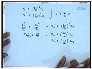
Therefore we will say r 1 dashed will be equal to N 2 by N 1 square into r 1. Similarly X l 1 dash equal to N 2 by N 1 square into X l 1 and we have already obtained v 1 dash equal to N 2 by N 1 into v 1. Regarding the shunt in branches again if we want the impendence’s I mean the power balance to be maintained then I should have E 2 square by R 0 dashed should be equal to E 1 square by R 0, or r 0 dashed should be equal to E 2 by E 1 whole square into R 0, but E 2 by E 1 equal to N 2 by N 1; therefore, R 0 dashed is equal to N 2 by N 1 square R 0. Similarly, X m dashed equal to N 2 by N 1 whole square X m.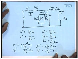
Therefore, the equivalent circuit of the single phase transformer refers to the secondary or the load side will be similar to the previous circuit except the parameter values will now be different; it is given by a similar circuit. Relationships are v 1 dash equal to N 2 by N 1 into v 1. I 1 dashed equal to N 1 by N 2 into I 1. I 0 dash equal to N 1 by N 2 into I 0. I c dash equal to N 1 by N 2 into I c, I m dash equal to N 1 by N 2 into I m. The parameters are r 1 dash equal to N 2 by N 1 square into r 1 X l 1 dash equal to N 2 by N 1 square into X l 1.
X m dash equal to N 2 by N 1 square X m, and r 0 dashed equal to N 2 by N 1 square into R 0. So, this is the equivalent circuit of a practical single phase transformer referred to the secondary or the load side while this was the equivalent circuit of the same single phase transformer referred to the primary or the source side. They are identical as far as the circuit structure are concerned they are identical except that the parameter values of the two circuits are different.
|
19 videos|95 docs|25 tests
|
FAQs on Modeling Of Single Phase Transformers - Electrical Machines - Electrical Engineering (EE)
| 1. What is the purpose of modeling single-phase transformers in electrical engineering? |  |
| 2. What are the main parameters considered in the modeling of single-phase transformers? | |
| 3. How is the turns ratio of a single-phase transformer determined in its modeling? | |
| 4. What is the significance of modeling the resistance in single-phase transformer analysis? | |
| 5. How does modeling the leakage inductance affect the behavior of single-phase transformers? | |


Modeling Of Single Phase Transformers | Electrical Machines - Electrical Engineering (EE)
,Free
,mock tests for examination
,Exam
,ppt
,study material
,past year papers
,Extra Questions
,Modeling Of Single Phase Transformers | Electrical Machines - Electrical Engineering (EE)
,Summary
,MCQs
,video lectures
,Semester Notes
,shortcuts and tricks
,Objective type Questions
,Modeling Of Single Phase Transformers | Electrical Machines - Electrical Engineering (EE)
,Previous Year Questions with Solutions
,Important questions
,practice quizzes
,Viva Questions
,Sample Paper
;


Modeling Of Single Phase Transformers Free PDF Download
Importance of Modeling Of Single Phase Transformers
Modeling Of Single Phase Transformers Notes
Modeling Of Single Phase Transformers Electrical Engineering (EE) Questions
Study Modeling Of Single Phase Transformers on the App
|
© EduRev
|
Education Revolution
|


|


