
Best Study Material for Electrical Engineering (EE) Exam
Electrical Engineering (EE) Exam > Electrical Engineering (EE) Notes > Electrical Machines > Parallel Operation Of Single Phase Transformers
Parallel Operation Of Single Phase Transformers | Electrical Machines - Electrical Engineering (EE) PDF Download
Parallel Operation of Single Phase Transformers
Good morning. Load on a practical transformer such as a distribution transformer it grows over time. As the, as more and more houses are electrified more on the load of each house increases, so does the load on the transformer. So, it may very well happen that within the life time of a distribution transformer or any other transformer, a transformer that was designed to the sufficient for a given load over a period of time; the transformer may reach its rated load and the load may even exceed it. So, there are 2 methods by which such a situation can be handled; 1 is replace the transformer by a larger transformer. However, it has some practical limitations.
For example, the larger transformer should again, should be planned for future expansion; which means, that the transformer rating should be relatively large compared to the present pick load. This also means, particularly for distribution transformer that, the new transformer will be operating at light load for most of the time which is not a very efficient utilization of the transformer.
The other approach is to connect a similarly rated transformer in parallel to the existing transformer; these are certain advantages. For example, even if the new transformer is of the same rating as the old transformer; then at least it allows for a growth of 100 percent in the load before a further replacement becomes necessary. Second thing, this new transformer need not always be connected. When the load is not sufficient only 1 transformer may be connected and it can supply at its rated capacity. Maintenance also becomes easy; because you need to keep only one spare small transformer. So, for these reasons parallel operation of transformers are important. And in this lecture we will find out how to connect 2 single phase transformer in parallel; what are the conditions for that and how to analyze parallel connected transformers.
(Refer Slide Time: 03:33)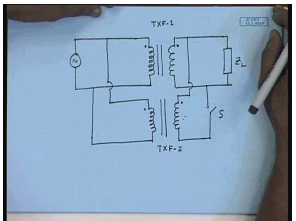
So, let us see. Suppose, we have 1 single phase transformer connected to the load, to the source on the primary side and supplies the load on the secondary side. This is let us say transformer 1. If I want to connect another transformer parallel to this; the primary of the 2 transformer will be connected in parallel to the source side, also the secondary. However, while connecting the secondary in parallel one should be careful about the instantaneous polarity of the voltages.
For example, this is the instantaneous positive terminal of the parallel connected primaries and this is the instantaneous positive terminal of the secondary of the first transformer. Then the instantaneous positive terminal of the second transformer must be connected to the instantaneous positive terminal of the first transformer and the other terminal should be connected like this. If not, then one can easily understand if this polarity is reversed; then even without this load, there will be a once this switch S is closed, there will be a short circuit through the transformer winding and a very large current will flow. So, this should be protected against.
So, before connecting the transformers in parallel, their instantaneous polarities should be checked and connected accordingly. This is the first condition for connecting 2 transformers in parallel, but this is not all. Obviously, one can appreciate that the no load voltages of the transformers should not be very different for the same reason. Because even if we assume that there is no load and the transformer secondary no load voltages are different. Then when you close this switch, there will be a circulating current flowing through the secondary’s, which will be limited only by the series impendence of the transformers which we have shown to be, which we have seen they are small; within typically, within 5 to 10 percent. So, even at no load, a very large current can flow; if the no load voltages of the 2 transformers are very different.
So, the transformers to be connected in parallel, should have instantaneous the correct polarity terminals connected together and then no load voltages should be very close; if not exactly equal. There are few other conditions which are not essential, but desirable and we will derive them. And of course, the total KVA rating of the 2 transformers must be greater than the total KVA demand of the load. It is for that purpose only that we are connecting the transformers in parallel. Now, let us see what other desirable conditions we can find out. For that we will need to analyze this parallel connected transformer and in the beginning, we will assume that the transformers have identical; no load primary and secondary voltages.
(Refer Slide Time: 08:18)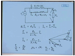
The equivalent circuit of the first transformer with respect to the load side can be shown to be like this; we have derived this before. Let us say this series impendence is Z 1 equal to R 1 plus j X 1. Since, the secondary transformer, the second transformer input are and output are connected to the same source and the same load; effectively the series impendence of the second transformer will come in parallel to the first transformer.
Therefore, the total equivalent circuit of the parallel connected transformers can be represented something like this. So, this is Z 2 equal to R 2 plus j X 2. Let us say the total current drawn by the first transformer is I 1; the current drawn by the second transformer is I 2 and total load current is I L. Then one can easily derive that Z 1 I 1 equal to Z 2 I 2 and I L equal to I 1 plus I 2. Therefore, in terms of I L, I 1 equal to Z 2 divided by Z 1 plus Z 2 into I L and I 2 equal to Z 1 divided by Z 1 plus Z 2 I L.
Now, let us try to see the phasor relationship between these currents and voltages. Let us say this is the load voltage phasor V L and this is the load current phasor I L. The vector sum of phasor sum of I 1 and I 2 is equal to I L. So, let us say this is I 1 and this is I 2. Then from this equivalent circuit we can show, this is V 1 dash. Similarly, this is equal to I 1 Z 1 equal to I 2 Z 2. This is how the phasor diagram will look like. Now, it is obvious from the phasor diagram that the current in the 2 transformers will be minimum when I 1 and I 2 are in same phase; because then I L will be the algebraic sum of I 1 and I 2. Therefore, one thing we can immediately say that one desirable condition for parallel connected transformer is that, when they are connected in parallel the currents drawn by them are in phase. That will happen only if; if I 1 and I 2 are to be in parallel, then I 1 by I 2 is equal to Z 2 by Z 1.
Therefore, if I 1 and I 2 have to be in phase, then the ratio of I 1 by I 2 will be a scalar and that will happen only if angle of Z 2 is equal to angle of Z 1. That is the ratio of R 1 by x 1 is equal to R 2 by x 2. So, this is a desirable condition; although not essential. This will ensure that for a given transformer current rating, the maximum load current can be supplied.
(Refer Slide Time: 15:05)
From the previous circuit diagram we have seen I 1 equal to Z 2 by Z 1 plus Z 2 into I L and I 2 bar equal to Z 1 divided by Z 1 plus Z 2 I L. Now, multiplying both sides of this equation with V L star; we get, where star denotes complex conjugate equal to Z 2 divided by Z 1 plus Z 2 into I L V L star. Now, V L star I 1 is the KVA complex, KVA supplied by transformer 1; while V L star I L is the complex KVA demanded by the load. Therefore, we can write S 1 equal to Z 2 divided by Z 1 plus Z 2 into S L. Similarly, S 2 equal to Z 1 divided by Z 1 plus Z 2 into S L or S 1 bar by S 2 bar equal to Z 2 by Z 1. Hence, if you look at the magnitude alone, S 1 by S 2 equal to mod Z 2 divided by mod Z 1.
Now, it is desirable that under any given load, under any given total load; the transformers share the load in proportion to their individual KVA rating, which means, for a any given load we would want S 1 divided by S 1 rated, should be equal to S 2 divided by S 2 rated. Therefore, this translates to S 1 divided by S 2 equal to S 1 rated divided by S 2 rated. That is, the transformers share the KVA, total load KVA in proportion to their individual KVA rating; but this we have seen to be equal to mod Z 2 divided by mod Z 1.
Hence, for sharing the load in proportion to their KVA, we find that the series impedance of the transformer; the magnitude of the series impendence of the transformers should be inversely proportional to their KVA rating. That is z, mod Z should be inversely proportional to S rated; so that is another desirable condition for connecting transformers in parallel. That is the series impendence of the transformer should be inversely proportional to their KVA rating. This can be stated even in a simpler form.
(Refer Slide Time: 19:15)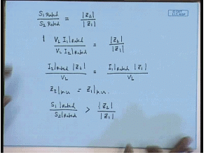
If we note that, the original relation is S 1 rated divided by S 2 rated equal to mod Z 2 rated mod Z 2 divided by mod Z 1 or S 1 rated can be written as V L I 1 rated divided by V L I 2 rated equal to mod Z 2 divided by mod Z 1. Or we can write I 2 rated into mod Z 2 divided by V L equal to I 1 rated mod Z 1 by V L. Now, if both the transformer has a rated secondary voltage of V L, then this is Z 2 per unit; p u is equal to Z 1 p u. Therefore, in simple terms the parallel connected transformer should have equal per unit series impendence on their own base. That will ensure that the transformers will share the total load KVA in proportion to their individual KVA rating. Now, suppose this condition is not satisfied. That is let us say, S 1 rated divided by S 2 rated is greater than mod Z 2 by mod Z 1; then what will happen?
(Refer Slide Time: 22:30)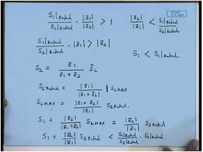
This thing can be written as into mod Z 1 by mod Z 2 larger than 1 or S 1 rated by S 2 rated into Z 1 is greater than Z 2. In which case, it can be easily shown that it is a second transformer which will share more load and reaches rated KVA earlier. Because we have seen, S 2 to be Z 1 divided by Z 1 plus Z 2 into S L.
Now, let us say under certain load condition S 2 has reached its rated KVA, S 2 rated. Therefore, S 2 rated equal to mod Z 1 divided by mod Z 1 plus Z 2 into mod S L; let us say S L max. S L max is the load KVA that is reached when S 2 reaches its rated KVA. In other words S L max is equal to mod Z 1 plus mod plus Z 2 divided by mod Z 1 into S 2 rated. So, what is the load on the first transformer then? S 1. S 1 is given by S 1 equal to mod Z 2 divided by mod Z 1 plus Z 2 into S L. And when S 2 reaches this rated KVA, then the load KVA is S L max; so this should be S L max. So, this can be written as substituting S L max on the previous equation, we get these to be mod Z 2 divided by mod Z 1 into S 2 rated.
But we have seen mod Z 2 from this relation we have seen mod Z 2 by mod Z 1 is less than S 1 rated divided by S 2 rated. Therefore, S 1 equal to mod Z 2 by mod Z 1 S 2 rated will be less than S 1 rated divided by S 2 rated into S 2 rated. Or the conclusion is S 1 in that case will be less than S 1 rated. Therefore, we see that if this relation is not satisfied, then one of the transformer with the lower series impendence reaches its KVA limit first and beyond which it will not be possible to load the parallel combination.
Therefore, the, but the other transformer will still have some capacity left. Therefore, in such a situation we will not be able to utilize the total KVA capacity of the 2 transformers. So, it is desirable that the per unit impendence of the transformers be same on their own base the impendence angle of the 2 transformers also be same; so that the total KVA can be maximized. Now, this was the analysis of parallel connected transformer assuming the 2 transformers have identical no load voltage. But in practical situation this is not always possible; there will be a small difference between the no load voltages of the 2 transformer in which case the question arises, how do we analyze parallel connected transformers?
(Refer Slide Time: 28:24)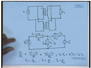
Again, this is the first transformer; the second transformer again is connected parallel to it with appropriate polarity. Now, these 2 transformer primaries are connected to the same source, but their induced voltages are slightly different. That is because their trans ratios are not exactly same. So, if we want to draw a equivalent circuit of this situation; then we must recognize that now this impendence will not exactly be connected in parallel. But for the first transformer we can still draw the equivalent circuit with respect to the load side. So, this will be V 1 1 dash; that is with respect to the secondary of the first transformer. This is the impendence of the first transformer series and this is the load impedance.
Similarly, we can draw the equivalent circuit of the second transformer. Now, since their trans ratio is different, the applied source referred to the secondary side of the second transformer will not be V 1 1 dash, but it will some other voltage V 1 2 dash; but they will be connected on the load side. Again, let us say this current is I 1, this current is I 2 and this is the total load current I L. So, this will be the equivalent circuit of the parallel connected transformer, when their no load voltages are not identical.
The problem is to find out the individual currents I 1 and I 2 contributed by the transformer when the total load current is I L. In order to achieve that, we can write the node voltage equation at this point. Assuming this voltage to be V L, we can write V L divided by Z L equal to V 1 1 dash minus V L by Z 1 plus V 1 2 dash minus V L by Z 2. Or V L Y L equal to V 1 1 dash Y 1 plus V 1 2 dash Y 2 minus V L Y 1 plus Y 2. Where Y L equal to 1 by Z L, Y 1 equal to 1 by Z 1 and Y 2 equal to 1 by Z 2.
(Refer Slide Time: 33:57)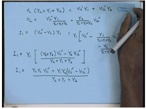
Hence, we can write V L into Y L plus Y 1 plus Y 2 equal to V 1 1 dash Y 1 plus V 1 2 dash Y 2. Or V L equal to V 1 1 dash Y 1 divided by Y L plus Y 1 plus Y 2 plus Y 2 divided by Y L plus Y 1 plus Y 2 V 1 2 dash. Therefore, the current I 1 equal to V 1 1 dash minus V L Y 1; this will be given by Y 1 into V 1 1 dash minus Y 1 divided by Y L plus Y 1 plus Y 2 V 1 1 dash minus Y 2 divided by Y L plus Y 1 plus Y 2 V 1 2 dash. Or I 1 equal to Y 1 into Y 1 plus Y L plus Y 2 into V 1 1 dash divided by minus Y 2 V 1 2 dash divided by Y L plus Y 1 plus Y 2. Or I 1 equal to Y L Y 1 V 1 1 dash plus Y 1 Y 2 V 1 1 dash minus Y 1 divided by Y L plus Y 1 plus Y 2. The value of I 2 can be found in a similar manner and once Y 1, I 1 and I 2 are found out; the KVA supplied by them, can also be determined. Now, let us look at a problem.
(Refer Slide Time: 38:13)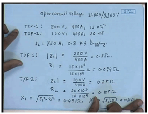
Let us say there are 2 single phase transformers with voltage rating open circuit voltage both of them. That is they have identical no load voltage; 11000 volts by 3.3 k V. Now, on short circuit test with the h V winding shorted the first transformer 1 get the following data. The applied voltage is 200 volts, the circulating current is 400 ampere and the dissipated power is 15 kilo watt. For the transformer 2, again with the h V winding shorted; the test data is applied voltage 100 volt, circulating current 400 ampere and power consumed is 20 kilo watt.
Now, these 2 transformers are connected in parallel and they supply a load current of I L of 750 ampere at a 0.8 p f lagging power factor. We have to find out the KVA supplied by each of these transformers and the load voltage. In order to do this, let us first find out the series impendence of the transformers. So, for transformer 1 mod Z 1 equal to 200 volts by 400 ampere is equal to 0.5 ohm. And R 1 equal to 15 into 10 to the power 3 divided by 16 into 10 to the power 4 ohm; that is equal to 0.094 ohm. For transformer 2 mod Z 2 equal to 100 volts by 400 ampere equal to 0.25 ohm. And R 2 equal to 20 into 10 to the power 3 divided by 16 into 10 to the power 4 equal to 0.125 ohm. Now, x 1 equal to square root Z 1 square minus R 1 square equal to 0.491 ohm; x 2 equal to square root Z 2 square minus R 2 square equal to 0.2165 ohm.
(Refer Slide Time: 42:58)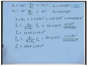
Therefore, we can write the angle theta 1 equal to cos inverse R 1 by Z 1; this comes to 79.1 degree. And theta 2 equal to cos inverse 0 point R 2 divided by Z 2; this comes to 60 degrees. So, Z 1 equal to 0.5 ohm angle 79.1 degrees and Z 2 equal to 0.25 ohm angle 60 degrees. Please note that here the impendence’s do not have the same angle. Nevertheless, we can still proceed in a similar manner. So, what is Z 1 plus Z 2? This comes to 0.7407 ohm angle 72.8 degrees. So, what will be the current I 1? I 1, we have seen to be equal to Z 2 divided by Z 1 plus Z 2 into I L; that is equal to 750 amperes 0.8 lagging power factor; that corresponds to minus 36.8 degree into 25 angle 60 degrees divided by 0.7407 angle 72.8 degrees. This gives you the current I 1 2. So, I 1 equal to 253 amperes angle minus 49.6 degrees.
Similarly, I 2 equal to Z 1 divided by Z 1 plus Z 2 I L equal to 750 angle minus 36.8 degrees into Z 1 is 0.5 angle 79.1 degrees divided by 0.7407 angle 72.8 degrees. This gives you I 2 equal to 506 amperes angle minus 30.5 degree. Please note that the algebra if these 2 currents are not in phase; therefore, their phasor sum instead of being 759 ampere, it is just 750 ampere. So, that is what happens that if the angle impendence angles of the series impendence are not same; the total current that you can supply reduces. Next, let us try to find out what will be the load voltage. For that let us try to draw the phasor diagram.
(Refer Slide Time: 47:12)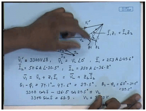
So, let us say this is the load voltage V L, I 1 is at a larger lagging angle of 49.6 degrees, but has smaller magnitude. I 2 have a larger magnitude, but a smaller angle. This is I 1, this is I 2 and this is the total current I L. So, the impedance drops like this and this is the applied voltage V 1 dash; let this angle be delta. Now, we know V 1 dash magnitude is 3.3 k V; because the applied voltage is 11 k V. Now, V 1 dash here equal to 3300 volts at an angle of delta. V L equal to magnitude of the load voltage at an angle at the 0; that is we are assume this to be the reference phasor I 1 equal to 253 amperes angle minus 49.6 degrees, I 2 equal to 506 amperes angle minus 30.5 degrees and I L, their phasor sum equal to 750 amperes angle minus 36.8 degrees. And this phasor is equal to I 1 Z 1 equal to I 2 Z 2.
Now, if this angle is phi 1 and this angle is phi 2; then we can write V 1 dash equal to V L plus Z 1 I 1 equal to V L plus Z 2 I 2. Now, this angle is the impedance angle of Z 1; that is this is theta 1 and this angle is the impendence angle of Z 2; that is theta 2. And this angle is phi 1 and this angle is phi 2. So, theta 1 minus phi 1 equal to 79.1 degrees minus 49.6 degrees equal to 29.5 degrees and theta 2 minus phi 2, that is also equal to 29.5 degrees. So, we can write from this phasor diagram 3300 cos delta minus 126.5 which is 0.5 into this, 0.5 into I 1 Z 1 I 1 cosine of 29.5 degrees. That will give you V L; also 3300 sine delta equal to 62.3. From which we will find out V L to be equal to 3190 volt.
(Refer Slide Time: 53:55)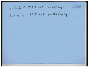
The KVA supplied by transformer 1, will be V L I 1 this comes to 807.5 KVA at a lagging power factor of 0.648 lagging power factor. And S 2 equal to V L I 2 this comes to 1615 KVA at 0.862 lagging power factor.
Thank you.
The document Parallel Operation Of Single Phase Transformers | Electrical Machines - Electrical Engineering (EE) is a part of the Electrical Engineering (EE) Course Electrical Machines.
All you need of Electrical Engineering (EE) at this link: Electrical Engineering (EE)
|
19 videos|95 docs|25 tests
|


FAQs on Parallel Operation Of Single Phase Transformers - Electrical Machines - Electrical Engineering (EE)
| 1. What is parallel operation of single phase transformers? |  |
| 2. How are single phase transformers connected in parallel? | |
Ans. Single phase transformers can be connected in parallel by connecting their primary windings to a common voltage source and their secondary windings to a common load. It is essential to ensure that the transformers have similar voltage ratios, impedance values, and turns ratios to ensure balanced load sharing.
| 3. What precautions should be taken when connecting single phase transformers in parallel? | |
Ans. When connecting single phase transformers in parallel, it is important to consider the following precautions:
- Ensure that the transformers have similar voltage ratios, impedance values, and turns ratios to ensure balanced load sharing.
- Use appropriate protection devices, such as fuses or circuit breakers, to protect each transformer from short circuits or overloads.
- Properly synchronize the transformers to avoid any phase difference or circulating currents.
- Regularly monitor the operation of each transformer to detect any abnormalities or imbalances.
| 4. What are the advantages of parallel operation of single phase transformers? | |
Ans. The advantages of parallel operation of single phase transformers include:
- Increased power capacity: By connecting transformers in parallel, the total power capacity can be increased, allowing for the addition of loads without overloading a single transformer.
- Redundancy: In case of a failure of one transformer, the remaining transformers can continue to supply power, ensuring uninterrupted operation.
- Load sharing: Parallel operation allows for the sharing of load among multiple transformers, preventing overloading of a single transformer.
- Flexibility: It provides flexibility in power distribution systems by allowing for the addition or removal of transformers as per the changing load requirements.
| 5. Can different types of single phase transformers be connected in parallel? | |
Ans. While it is possible to connect different types of single phase transformers in parallel, it is not recommended. Different types of transformers may have variations in their voltage ratios, impedance values, and turns ratios, which can lead to imbalanced load sharing and inefficient operation. It is best to connect transformers that are specifically designed for parallel operation to ensure proper load sharing and compatibility.
Related Exams
About this Document

4.94/5
Rating

Apr 23, 2025
Last updated
Document Description: Parallel Operation Of Single Phase Transformers for Electrical Engineering (EE) 2025 is part of Electrical Machines preparation.
The notes and questions for Parallel Operation Of Single Phase Transformers have been prepared according to the Electrical Engineering (EE) exam syllabus. Information about Parallel Operation Of Single Phase Transformers covers topics
like and Parallel Operation Of Single Phase Transformers Example, for Electrical Engineering (EE) 2025 Exam. Find important definitions, questions, notes, meanings, examples, exercises and tests below for Parallel Operation Of Single Phase Transformers.
Introduction of Parallel Operation Of Single Phase Transformers in English is available as part of our Electrical Machines
for Electrical Engineering (EE) & Parallel Operation Of Single Phase Transformers in Hindi for Electrical Machines course.
Download more important topics related with notes, lectures and mock test series for Electrical Engineering (EE)
Exam by signing up for free. Electrical Engineering (EE): Parallel Operation Of Single Phase Transformers | Electrical Machines - Electrical Engineering (EE)
Description
Full syllabus notes, lecture & questions for Parallel Operation Of Single Phase Transformers | Electrical Machines - Electrical Engineering (EE) - Electrical Engineering (EE) | Plus excerises question with solution to help you revise complete syllabus for Electrical Machines | Best notes, free PDF download
Information about Parallel Operation Of Single Phase Transformers
In this doc you can find the meaning of Parallel Operation Of Single Phase Transformers defined & explained in the simplest way possible. Besides explaining types of
Parallel Operation Of Single Phase Transformers theory, EduRev gives you an ample number of questions to practice Parallel Operation Of Single Phase Transformers tests, examples and also practice Electrical Engineering (EE)
tests

Related Searches
ppt
,Parallel Operation Of Single Phase Transformers | Electrical Machines - Electrical Engineering (EE)
,MCQs
,past year papers
,Summary
,Free
,shortcuts and tricks
,Parallel Operation Of Single Phase Transformers | Electrical Machines - Electrical Engineering (EE)
,Viva Questions
,Extra Questions
,Objective type Questions
,Semester Notes
,study material
,Parallel Operation Of Single Phase Transformers | Electrical Machines - Electrical Engineering (EE)
,Previous Year Questions with Solutions
,Important questions
,mock tests for examination
,practice quizzes
,Sample Paper
,Exam
,video lectures
;


Additional Information about Parallel Operation Of Single Phase Transformers for Electrical Engineering (EE) Preparation
Parallel Operation Of Single Phase Transformers Free PDF Download
The Parallel Operation Of Single Phase Transformers is an invaluable resource that delves deep into the core of the Electrical Engineering (EE) exam.
These study notes are curated by experts and cover all the essential topics and concepts, making your preparation more efficient and effective.
With the help of these notes, you can grasp complex subjects quickly, revise important points easily,
and reinforce your understanding of key concepts. The study notes are presented in a concise and easy-to-understand manner,
allowing you to optimize your learning process. Whether you're looking for best-recommended books, sample papers, study material,
or toppers' notes, this PDF has got you covered. Download the Parallel Operation Of Single Phase Transformers now and kickstart your journey towards success in the Electrical Engineering (EE) exam.
Importance of Parallel Operation Of Single Phase Transformers
The importance of Parallel Operation Of Single Phase Transformers cannot be overstated, especially for Electrical Engineering (EE) aspirants.
This document holds the key to success in the Electrical Engineering (EE) exam.
It offers a detailed understanding of the concept, providing invaluable insights into the topic.
By knowing the concepts well in advance, students can plan their preparation effectively.
Utilize this indispensable guide for a well-rounded preparation and achieve your desired results.
Parallel Operation Of Single Phase Transformers Notes
Parallel Operation Of Single Phase Transformers Notes offer in-depth insights into the specific topic to help you master it with ease.
This comprehensive document covers all aspects related to Parallel Operation Of Single Phase Transformers.
It includes detailed information about the exam syllabus, recommended books, and study materials for a well-rounded preparation.
Practice papers and question papers enable you to assess your progress effectively.
Additionally, the paper analysis provides valuable tips for tackling the exam strategically.
Access to Toppers' notes gives you an edge in understanding complex concepts.
Whether you're a beginner or aiming for advanced proficiency, Parallel Operation Of Single Phase Transformers Notes on EduRev are your ultimate resource for success.
Parallel Operation Of Single Phase Transformers Electrical Engineering (EE) Questions
The "Parallel Operation Of Single Phase Transformers Electrical Engineering (EE) Questions" guide is a valuable resource for all aspiring students preparing for the
Electrical Engineering (EE) exam. It focuses on providing a wide range of practice questions to help students gauge
their understanding of the exam topics. These questions cover the entire syllabus, ensuring comprehensive preparation.
The guide includes previous years' question papers for students to familiarize themselves with the exam's format and difficulty level.
Additionally, it offers subject-specific question banks, allowing students to focus on weak areas and improve their performance.
Study Parallel Operation Of Single Phase Transformers on the App
Students of Electrical Engineering (EE) can study Parallel Operation Of Single Phase Transformers alongwith tests & analysis from the EduRev app,
which will help them while preparing for their exam. Apart from the Parallel Operation Of Single Phase Transformers,
students can also utilize the EduRev App for other study materials such as previous year question papers, syllabus, important questions, etc.
The EduRev App will make your learning easier as you can access it from anywhere you want.
The content of Parallel Operation Of Single Phase Transformers is prepared as per the latest Electrical Engineering (EE) syllabus.
|
© EduRev
|
Education Revolution
|


|


Signup to see your scores
go up within 7 days!
Access 1000+ FREE Docs, Videos and Tests
Takes less than 10 seconds to signup