Introduction to Three-Phase Transformers | Electrical Machines - Electrical Engineering (EE) PDF Download
What is a Three Phase Transformer?
- Three-phase transformers are essential electrical devices used in various industries. Understanding them is vital for electrical engineers to design and maintain systems for a wide range of applications.
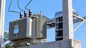 Three Phase Transformer
- The main role of a three-phase transformer in providing electricity is to efficiently and safely adjust voltage levels for the distribution of electrical power. It accomplishes this by converting higher voltage electricity from power plants into lower voltage levels suitable for industrial, commercial, and residential use.
- A three-phase transformer operates with a three-phase power supply, with both primary and secondary windings featuring three sets of windings.
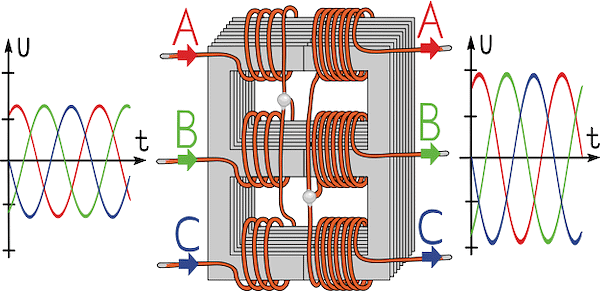 A three-phase transformer having three sets of windings on both primary and secondary sides
- The size, design, volt-ampere rating, and load-handling capacity of a 3- Φ transformer vary based on the specific industry or application.
Let's explore the technical aspects of a three-phase transformer, including its working principles and construction details.
Working Principle of Three Phase Transformer
The working principle of a three-phase transformer is based on Faraday's law of induction, which tells us that the magnitude of the emf induced within a circuit is directly proportional to the rate of change of the magnetic flux cutting across the circuit.
Here's how it works:
- Primary Windings: In a three-phase transformer, you have the primary windings. These are like the starting point. They're usually connected to an AC power source, creating a changing magnetic field, often using electromagnets.
- Secondary Windings: Next, you have the secondary windings. These windings are like the endpoint. As the magnetic field around the primary windings keeps changing, it also changes around the secondary windings. This changing magnetic field induces an electric current in the secondary windings.
- Frequency Match: It's important to note that the frequency of the electricity remains the same in both the primary and secondary windings. This means if you have a 60 Hz AC supply in the primary, you'll get 60 Hz AC electricity in the secondary as well.
Three-Phase Transformer Constitution
- Insulation: This component serves as a protective barrier, separating the windings from the transformer's core.
- Transformer Oil: Transformer oil serves a dual purpose: it acts as both an insulator and a coolant. Its insulating properties prevent electrical short circuits and arcing, while it also functions as a cooling agent, dissipating heat from the core and windings.
- Thermometers: Thermometers are used to monitor the temperature of the transformer oil, ensuring it stays within safe operating limits.
- Pressure Relief Systems: These systems are an integral part of safety measures. They activate in cases of overpressure, particularly when the oil is at risk of flashing due to short circuits, safeguarding the transformer.
- Cooler: The cooling system is responsible for regulating the temperature of the coolant. It accomplishes this by cooling down the hot oil using water or air-cooled tubes. The cooled coolant is then returned to the core and windings.
- Tank: The tank serves a protective function, shielding the transformer windings and core from external environmental conditions. It also contains the coolant.
- Oil Conservator: Installed separately from the tank, the oil conservator plays a role in managing oil volume changes caused by temperature variations within the windings and core.
- Voltage Regulators: Voltage regulators are responsible for adjusting the transformer's output voltage, compensating for any drops that may occur during high-demand periods. They achieve this by modifying the tapping turns through a tap changer.
- Gas-Actuated Relay: Also known as the Buchholz relay, this device detects and collects released gas that might escape from the transformer tank. The presence of this gas signals potential issues with the transformer.
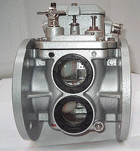 Buchholz Relay
- Breathers: Breathers play a vital role in maintaining the dryness of the transformer oil by removing moisture from the air space above the oil in the conservator.
Construction of Three Phase Transformer
The three-phase transformer construction is of two types:
- Core type
- Shell type
1. Core Type
- In core-type three-phase transformers, the core has three limbs within the same plane.
- Each limb contains primary and secondary windings, and these windings are evenly split among the three limbs. Commonly primary and secondary windings are referred as high voltage (HV) and low voltage (LV) windings respectively.
- As a low voltage winding is easier to insulate, these windings are closer to the core than the higher voltage coils.
- The latter windings wrap around the former, with insulative material between them.
- This construction has the windings magnetically linked with one another, with one winding using the other pair of limbs as return paths for its magnetic flux.
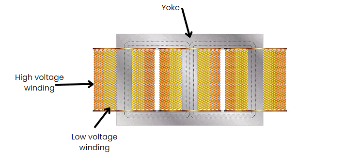 Core Type Transformer
2. Shell Type
- The shell-type 3-phase transformer is similar to three separate 1-phase transformers.
- The three phases of this transformer have their magnetic fields virtually independent, and this transformer's core has five limbs as seen in figure below.
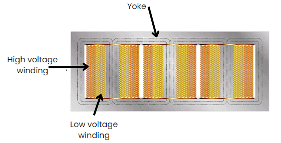 Shell Type Transformer
- The HV and LV windings exist around the three main limbs. Like the core-type 3-phase device, the low voltage coil is nearest the core. The two outermost limbs serve as the flux's return paths.
- Magnetic flux divides in two as the field approaches the yoke. It's common for the outer limbs and the yoke to be half the size of the main limbs.
- We can decrease the transformer's height by reducing the yoke's size.
Winding Diagrams of Three Phase Transformers
In a three-phase transformer, the primary and secondary windings can have different or similar configurations.
There are four main possible combinations:
1. Star-Star (Y-Y)
- Star-star connection is generally used for small, high-voltage transformers. Because of star connection, number of required turns/phase is reduced (as phase voltage in star connection is 1/√3 times of line voltage only). Thus, the amount of insulation required is also reduced.
- The ratio of line voltages on the primary side and the secondary side is equal to the transformation ratio of the transformers.
- Line voltages on both sides are in phase with each other.
- This connection can be used only if the connected load is balanced.
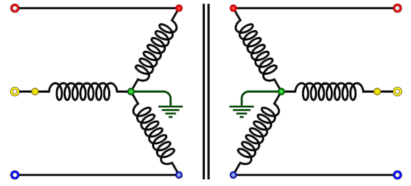 Star-Star Connection
2. Delta-Delta (Δ-Δ)
- This connection is generally used for large, low-voltage transformers. Number of required phase/turns is relatively greater than that for star-star connection.
- The ratio of line voltages on the primary and the secondary side is equal to the transformation ratio of the transformers.
- This connection can be used even for unbalanced loading.
- Another advantage of this type of connection is that even if one transformer is disabled, system can continue to operate in open delta connection but with reduced available capacity.
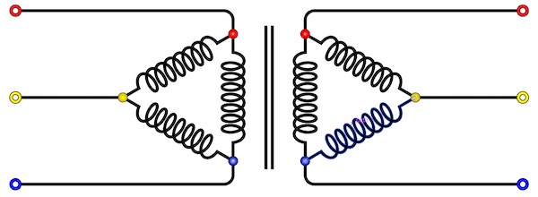 Delta-Delta Connection
 |
Download the notes
Introduction to Three-Phase Transformers
|
Download as PDF |
3. Star-Delta or Wye-Delta (Y-Δ)
- The primary winding is star (Y) connected with grounded neutral and the secondary winding is delta connected.
- This connection is mainly used in step down transformer at the substation end of the transmission line.
- The ratio of secondary to primary line voltage is 1/√3 times the transformation ratio.
- There is 30° shift between the primary and secondary line voltages.
4. Delta-Star or Delta-Wye (Δ-Y)
- The primary winding is connected in delta and the secondary winding is connected in star with neutral grounded. Thus it can be used to provide 3-phase 4-wire service.
- This type of connection is mainly used in step-up transformer at the beginning of transmission line.
- The ratio of secondary to primary line voltage is √3 times the transformation ratio.
- There is 30° shift between the primary and secondary line voltages.
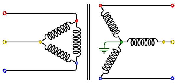 Delta-star Connection
There are two other configurations besides the four main permutations. These others are a product of altering primary delta and star windings. They include:
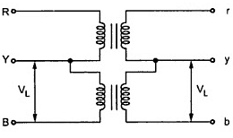
Open Delta (V-V) Connection
- Two transformers are used and primary and secondary connections are made as shown in the figure below.
 Open Delta Connection
- Open delta connection can be used when one of the transformers in Δ-Δ bank is disabled and the service is to be continued until the faulty transformer is repaired or replaced. It can also be used for small three phase loads where installation of full three transformer bank is un-necessary.
- The total load carrying capacity of open delta connection is 57.7% than that would be for delta-delta connection.
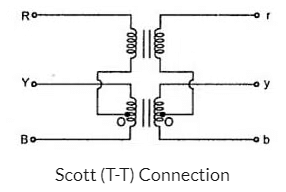
Scott (T-T) Connection
- Two transformers are used in this type of connection.
- One of the transformers has centre taps on both primary and secondary windings (which is called as main transformer).
- The other transormer is called as teaser transformer. Scott connection can also be used for three phase to two phase conversion. The connection is made as shown in the figure below.
PYQs: Competitive Exams
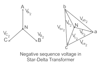
Q: Which three-phase connection can be used in a transformer to introduce a phase difference of 30° between its output and corresponding input line voltages [2005]
(a) Star - Star
(b) Star - Delta
(c) Delta - Delta
(d) Delta-Zigzag
Ans: b
Sol:
There is no phase shift between the star-star and delta-delta 3-phase transformer.
- Most of the transformers are either star-delta or delta-star connected.
- Consider a 3-phase star-delta transformer with primary side Y connected (star connected) and secondary side with delta connected as shown below
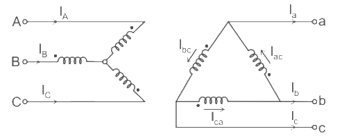
- The polarity markings are indicated on each phase.
- The dots on the winding indicate the terminals which are positive at the same time on the undotted terminals.
- Phase on star side – A, B, C
- Phase on delta side – a, b, c
- The labeling is indicated to the diagram corresponding to +90° connections in which the positive sequences on the delta side are lead by 90° corresponding to the star side.
- Thus the line current flows through the phase and A.
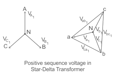
- If we label delta as b → a, c → b, and a → c. There we will get standard Yd1, –30° connection
- If polarities on the delta side are also reversed, we get standard Yd11, 30° connection as shown in the figure given below.
- Thus we can get a phase difference of 30° between input and output of three-phase transformer by using a star-delta connection.
|
19 videos|95 docs|25 tests
|
FAQs on Introduction to Three-Phase Transformers - Electrical Machines - Electrical Engineering (EE)
| 1. What is the purpose of a three-phase transformer? |  |
| 2. How does a three-phase transformer work? |  |
| 3. What is the construction of a three-phase transformer? |  |
| 4. What are the winding diagrams of a three-phase transformer? |  |
| 5. What are the applications of three-phase transformers? |  |


