Auto Transformers
You can recall that we introduced the concept of a 2 angle transformer through a inductive potential divider of this form.
(Refer Slide Time: 00:57)
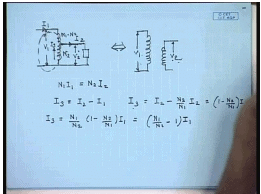
That is, if we give a input voltage of V 1 then we will get a output voltage of V 2, which is different from V 1 and from here we arrived at the concerto of 2 winding transformer showing that these 2 parts can be separated out unlike a resistive potential divider. The reason being the power transform for transfer from input to output, in this case occurs not only by the conductive path like this, but also by magnetic induction, by that we means when we apply a voltage here a flux is produced leaves both part of the coil, and when a load is connected here the current flowing through the load tries to change the flux as a result a reflection current is drawn from the primary side. A part of the power is transferred by the conductive path, but a part is transferred by the inductive part as well.
While therefore, if we say this current is I 1 this current is I 2 then and this current is I 3 then the phasor diagrams of I 1 I 2 I 3 can be drawn as follows, assuming negligible magnetization current, if we say this number of turns of this part is N 2 and this part is N 1 - N 2 then from balance of N m f we can say N 1 I 1 equal to N 2 I 2. So, that the net magnetization current is 0 in ideal transformer. Therefore, what is I 3? I 3 equal to I 2 minus I 1. In other words I 3 equal to I 2 minus N 2 by N 1 into I 2 equal to 1 minus N 2 by N 1 into I 2 is same as or I 3 equal to N 1 by N 2 into 1 - N 2 by N 1 I 1 equal to N 1 by N 2 minus 1 into I 1. From this expression, we can see N 2 by N 1 is larger than 0 therefore, we can see that the current I 3 will be smaller than the current I 2, that s because, the I 3 is the current due to induction, where as the rest of the current follows by conduction.
So, in a auto transformer power transfer takes place both by electrical conduction and magnetic induction, and hence certain advantages result. For example, if the turns ratio N 2 by N 1 is close to 1 then I 3 will be very small compared to I 2 and therefore, the current carrying capacity of this part of the winding will can be designed to be low and hence there is a possibility of considerable saving in the copper, which is a the advantage for this kind of a arrangement this is called a auto transformer. This advantage does not exceed exist in a 2 winding transformer, where the entire power transfer is by inductive method.
(Refer Slide Time: 06:36)
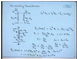
Let us look at a few examples of the advantages of this auto transformer. For example, let is compare the losses in both cases for the 2 winding transformer, let us say this is the 2 winding transformer A 2 A 1 a 2 a 1. Let this current be I a, this current be I b, number of turns here N a, number of turns here N b, resistance of this winding let us say is R a, resistance of this winding is R b therefore, the total copper loss in this 2 winding transformer will be I a square R a plus I b square R b equal to P copper loss in 2 winding. Now, if we join this windings to form a auto transformer we can join this point to this and this point to this that this stepping being the point, where the voltage is same as the voltage between a 2 and a 1 then the operation of the transformer does not change. At the same operating condition, this is now call it A 3 A 1 and a2 say the current is again I b here now, this are there are N b number of turns and these number of turns is N a minus N b.
Let this current be I a, in this case the power loss is P c u auto transformer is equal to I a square into R 1 plus I a, this current is I c, which is I a minus I b square R 2, where R 1 is the resistance of this part of the winding and R 2 is the resistance of this part of the winding. Now, the current on the upper part of the auto transformer and that of the 2 winding transformer are same. Therefore, assuming same current density the conductor cross section in of the 2 winding transformer hv winding and upper part of the auto transformer are same. Hence, the resistances depend on the number of turns therefore, R 1 can be written as N a minus N b divided by Na into Ra let us call it that is 1 minus alpha R a where alpha equal to N b by N a.
To calculate the resistance R2 we note that the number of turns of the l v winding of the 2 winding transformer and the number of turns of the lower part of the auto transformer are same; however, while the current in the l v winding is I b the current in the lower part of the auto transformer is I c, where I c equal to I b minus I a. Now, again if we assume the current densities of this winding and in this part of the winding to be same, then the cross sectional area of the conductors on the l v winding of the auto transformer and the l v winding of the 2 winding transformer of the hv winding lower part of the auto transformer should be inversely proportional to the current carrying capacity. Hence, if we say that the conductor cross section here is A b and the conductor cross section here is A 2 .
Then A b by A 2 will be equal to the inversely proportional equal to I b divided by I b minus I a that is A b divided by I b divided by A b, which is the current density of this winding should be equal to I b minus I a divided by A 2, which is the current density in this part of the winding. Now, R 2 by R b resistance is inversely proportional to the cross sectional area R 2 by R b equal to A b by A 2 that is equal to I b divided by I b minus I a. Hence, the total I square R loss in the auto transformer will be P c u auto equal to 1 minus alpha R a I a square plus R 2 is given by, I b divided by I b minus I a into R b into I b minus I a square equal to 1 minus alpha R a I a square plus I b into I b minus I a R b but, if we neglect the magnetization current.
(Refer Slide Time: 15:10)
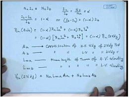
Then N a I a equal to N b I b hence I a by I b equal to N b by N a equal to alpha therefore, I b minus I a by I b equal to 1 minus alpha or I b minus I a equal to 1 minus alpha into I b. Hence, the copper loss in the auto transformer should be equal to 1 minus alpha into R a I a square plus 1 minus alpha R b I b square equal to 1 minus alpha into R a I a square plus R b I b square, which is the power loss in the 2 winding transformer equal to 1 minus alpha into P c u 2 winding. So, we see for the same rating, if the 2 winding transformer and the auto transformer are supplying the same load then the auto transformer will have lower loss not only that you’ll find that the auto transformer will also use lower copper volume.
For that, let us define A a to be the cross section of the of h v winding of the 2 winding transformer and A b cross section of l v winding of the 2 winding transformer. Let L m a be the mean length of turn of H v winding and L m b mean length of turn of L v winding. When the total copper used in the 2 winding transformer V c u 2 winding equal to copper used in the l v winding, which is N a into L m a into A a plus copper used in the l v winding, which is N b L m b A b. So, this is the volume of the copper used in the 2 winding transformer. Let us, now compute the volume of copper used in the auto transformer having the same k v a rating.
(Refer Slide Time: 19:46)
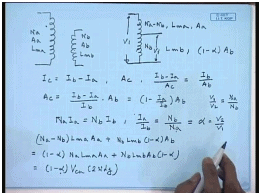
For that, this is the 2 winding transformer, number of turns N a, cross sectional area A a , mean length at turn L m a, number of turns N b, cross sectional area A b, mean length of turn L m b for the other transformer having the same k v a rating and the voltage rating. Number of turns here is N b, number of turns here is N a minus N b, mean length of turn here let us say still L m a and here it is L m b. Now, let us consider the cross sectional area this part of the auto transformer and the h v winding of the 2 winding transformer carrier the same current, if the 2 transformer have same k v a rating. Therefore, their cross sectional areas should also be same. So, this part as a cross sectional area of A a; however, the current carrying capacity of this part of the 2 winding of the auto transformer is I c, which is I b minus I a whereas, for this it is I b therefore, the current carrying capacity of the lower part of the auto transformer is I c equal to I b minus I a.
So, if this part has a cross sectional area of A c the current density is I b minus I a by A c this should be same as the current density of the l v winding of the 2 winding transformers. So, this should be equal to I b minus I b by A b. Therefore, A c equal to I b minus I a by I b into A b 1 minus I a by I b into A b, but we have seen for negligible magnetization current N a I a equal to N b I b hence I a by I b equal to N b by N a equal to alpha. Therefore, the volume of the lower part of the auto transformer will the cross sectional area of the lower part of the auto transformer will be 1 minus alpha into A b. Hence, the volume of the copper in the auto transformer will be N a minus N b into L m a A a plus N b L m b 1 minus alpha A b equal to 1 minus alpha into Na L m a A a plus N b L m b A b into 1 minus alpha hence this is also equal to 1 minus alpha volume of copper in a 2 winding transformer.
Hence, see that for the same k v a rating the auto transformer will give lower losses as well as will use lower copper volume; however, as we have mentioned in the beginning it will not provide electrical isolation between the 2 sites therefore, where the electrical isolation is necessary we cannot use a auto transformer but; however, if the electrical isolation is not very important it is advantageous to use auto transformer particularly when the quantity alpha that is N b by N a which incidentally is also the voltage ratio if this voltage is V1 and this voltage is V 2 then we know V 1 by V 2 equal to N a by N b. So, alpha equal to V 2 by V 1, so if the quantity V 2 by V 1 that is the voltage combustion ratio is close to unity then this quantity 1 minus alpha is almost 0.
Hence, there will be a large saving in copper and also a large saving in losses. Hence, if the requirement of electrical isolation is not very important and the voltage combustion ratio is close to unity then it is advantageous to use a auto transformer rather than a 2 winding transformer. Generally auto transformers are suitable for a value of alpha between 1 to 0.5.
(Refer Slide Time: 26:49)
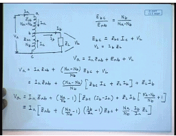
Now, that we know about the advantages of a auto transformer let us pay our attention to analyses of an auto transformer how do I analyse a auto transformer. For that, let us assume that this auto transformer is supplied with a voltage of V a on the h v site draws a current of I a here and the output is taken from here supplies to a load Z L ((Refer Time: 27:27)) load for the time being we will assume with a current of I b this point let us call it a this b this c.
This current is I a this current is I b this current is I c and the load voltage here is V L, the number of turns in this section is N b and in this section is N a minus N b. Therefore, we can write its just to be noted that the coil of a auto transformer is on a magnetic core on hence the both the parts of the winding brings the same magnetization flux therefore, we can write that E b c that is the voltage induced in the part it turns N b divided by E a b is equal to N b divided by N a minus N b and they will also be in phase from k b l we can write the induced voltage E bc equal to the leakage impedance of this part Ebc Zbc into the current I c plus load voltage V L, where V L equal to I b into Z L. Similarly, we can write the applied voltage V a to be equal to the drop across the leakage impedance of the section A b that is I a into Z a b plus the induced voltage in the section A b that is E a b plus the load voltage VL.
Now, substituting from above equations we can write V a equal to I a Z a b plus N a minus N b by N b into E b c that is what E a b is plus V L on further substitution we get equal to I a Z a b plus N a minus N b by N b into Z b c I c plus Z L I b plus Z L I b or V a equal to I a Z a b plus N a minus by N b minus 1 into Z b c I c equal to I b minus I a plus Z L I b into N a minus N b by N b plus 1. This can be written as, I a into Z a b plus N a by N b minus 1 into I b by I a minus 1 into Z b c plus N a by N b into I b by I a Z L.
(Refer Slide Time: 34:11)
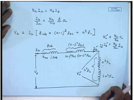
Again, if we neglect the magnetization current of the auto transformer we can write N a I a equal to N b I b or I b by I a equal to N a by N b let us define this quantity to be a, this is also same as the open circuit voltage of the auto transformer. Hence, we can write V a to be equal to I a into Z a b plus a minus 1 square into z b c plus a square into Z L. Hence, the equivalent circuit of the auto transformer can be drawn as this is R a b this is j X a b, where this quantity is Z a b this is a minus 1 square R b c this is a minus 1 square j a minus 1 square X b c hence this part is a minus 1 square Z b c this is a square R L this is j a square X L. Hence this quantity is a square Z L this is the referred load voltage V L dash and this is the referred load current I b dash. What is the relationship between V L dash and I b dash? V L dash equal to multiplies by the turns ratio that is N a by N b into V L and I b dash equal to N b by N a into I b.
So, that V L dashed I b dashed equal to V L I b. This is also same as I a since we have neglected the magnetization current. So, this equivalent circuit is similar to that of a approximate equivalent circuit of a 2 winding transformer except that for the lower part of the auto transformer we will have to use the turns ratio as a minus 1 rather than a. For a 2 winding transformer with the same number of turns it would have been a square into the leakage impedance of this part. Now, that tells that not only a auto transformer we will have lower loss and lower copper volume it will also have much lower leakage inductance or leakage reactance hence the voltage regulation of a auto transformer will also be better compared to a 2 winding transformer. How do you draw a phasor diagram for this auto transformer for that, let us draw the auto transformer again.
(Refer Slide Time: 39:33)
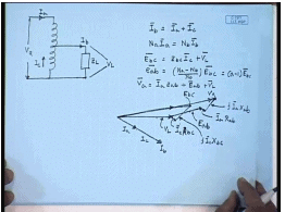
This is the voltage V a current I a and let us say we are drawing load current I b to a load impedance Z L, which we will assume to be inductive and this is the voltage V L. So, let this be the phasor of the load voltage V L and since this is lagging impedance this is a inductive load the current I b will be lagging V L by the power factor angle. So, this is the current I 2 or I b the current I a and I c are in phase with I b; however. So, this is the current I b the current I a is a fraction of I b because for the current relations we are I b equal to I a plus I c and also N a I a equal to N b I b, if you neglect the magnetization current. So, this is the current I a and the rest is the current I c.
Now, from the first equation that is E b c equal to Z b c I c plus V L we can get the phasor E b c, which will be this is the phasor E b c, but we know E a b equal to N a minus N b by N b into E b c equal to a minus 1 to E b c. Since auto transformers are normally used with a less than 2 E a b will be in phase with E b c, but of smaller magnitude. Now, let us use the other equation that is V a equal to I a Z a b plus E a b plus V L this is E b c, a will be in phase with E b , but of smaller magnitude. So, let us assume this is E a b this is V L plus E ab plus I a is in phase with I b I a R a plus j I a X a. Hence, this will be the phasor V a, this is the phasor E b c this is the phasor E a b this is the phasor V L this phasor is I c Z b c R b c this phasor is j I c X b c. Similarly, this phasor is I a R a b and this phasor is j I a X ab. So, this will be the phasor diagram of the auto transformer. Now, let us solve the problem concerning the auto transformer to understand whatever has been taught so far.
(Refer Slide Time: 45:32)
For that, let us take this example you have a 10 k v a 1.1 k v by 440 volt single phase 2 winding transformer. So, this is the 2 winding transformer, this is A2 A1 this is a2 a1 this rated voltage is 1.1 k v, 10 k v a relative voltage here is 440 volt again the k v rating is 10 k v a, if you wish to connect it in terms of an auto transformer what are the different possible connection. Obviously, there are 2 possibilities 1 is this is the part A2 A1 connected in series with the smaller part a2 a1 and we take the output from here. So, what will be the voltage ratio here the maximum voltage that can appear and this site is 440 volt. The maximum voltage that can appear here is 1.1 k v hence, the voltage ratio V 1 by V2 or V2 by V1 here can be 440 divided by 1100 plus 440 equal to 440 divided by 1540 this is the voltage conversion ratio. What will be the current carrying capacity? The current carrying capacity of the section A2 A1 is I A2 A1 equal to 10 k v a 10 into 10 to the power 3 divided by 1.1 k v this comes to 9.091 amperes. The current carrying capacity of the section a2 a1 will be I a2 a1 that part it is again 10 k v a because we have joined these 2 in series. So, their current carrying capacity do not change divided by 440 volt this comes to 22.73 amperes. Therefore, the maximum value of the current output current I 2 I 2 max will be the sum of these 2 this should be equal to 31.82 amperes. Hence, the k v a rating will be V1IA2A1 equal to V2I2 max this comes to about 14 k v a hence when I connect a 2 winding transformer the 2 as an series I get a auto transformer whose k v a rating increases to 14 k v a there’s another connection possible, where the section a2 a1 is connected on the top. (Refer Slide Time: 52:01) And the section capital a2 a1 is connected on the bottom in this that is here a2 a1 and here A2 A1 this part has a, and the output is taking across the high voltage winding. So, this part has a rated voltage of 1.1 k v and this part has a rated voltage of 440 volts. He nce, here the voltage conversion ratio will be here the V2 by V1 equal to 1100 divided by 1540 going by the same logic. Similarly, if the current carrying capacity here I a2 a1 is equal to 22.73 amperes whereas, the current carrying capacity I A2 A1 is 9.091 amperes means I2 max in this case also equal to 31.82 amperes now the k v maximum k v a that is V2 into I2 max comes to about 35 k v a. So, a 10 k v a 2 winding transformer can supply 35 k v a when connected as the auto transformer it is easy to see here the value of alpha was much lower than 1 hence the increase in the k v was not all that great here the value of alphas is equals to 1 hence we get almost 3.5 times increase in the k v a rating of the auto transformer. Thank you.


