Armature Reaction
(Refer Slide Time: 00:29)

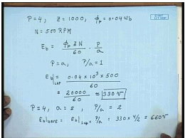
Let us see, an example of how to calculate the induced voltage in a dc machine armature. Let us consider, dc machine with an armature winding which is own for, let say 4 pole equal to 4 and the total number of armature conductor z equal to let us say 1000. The flux per pole phi p equal to 0.04 Weber and the machine is rotating at a speed N equal to 500 R P M. So, what will be the induced voltage? This is the simple application of the formula E b equal to phi p z N by 60 into p by a. Since this is lap connected armature therefore, p equal to a and p by a equal to 1.
Therefore E b equal to phi p is 0.04 into z is 1000 so that is 10 to the power 3 into 500 divided by 60, that is equal to 20000 by 60 approximately equal to 330 volts. Now, if the same armature is beyond as a wave winding, two circuit wave winding in which case the poles will be remain same number that is four, but now for the wave connection, it will be than a equal to 2 therefore, p by a will now be 2 and hence this is for lap connection E b for wave connection will be E b lap multiplied by p by a that is 330 into 4 by 2 that is equal to 660 volts, so the wave connection the machine will generate higher voltage, but if the power increase. Let us see, the same conductors are connected either as wave or else lap. So, due to connection their current carrying capacity does not change.
(Refer Slide Time: 04:17)
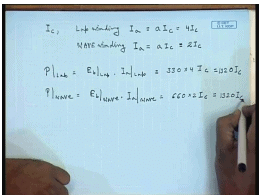
So, let us say, the current carrying capacity is the conductor is I c, then for lap connection armature current I a, maximum armature current I a will be a into I c that is 4 I c, where as for wave winding I a will still be given by a I c, but now a equal to 2 so this is the 2 I c. So, power for the lap is E b lap into I a lap equal to 330 into 4 I c, power wave equal to E b for wave connection into I a wave connection this will be 660 into 2 I c. This is equal to 1320 I c; this is also 1320 I c.
So, we see although the generated voltage at the same speed will be higher for the wave connected machine its armature current will reduce and hence the total power produce as a generator either due to wave connection or due to lap connection will remain same, but depending on the required voltage. We chose the armature connection that is if a higher voltage machine is required higher voltage localized machine is required then wave winding will be preferred if a low voltage high current is required then lap winding will be preferred. So, far we have seen the effect of field pool only on the generated voltage and torque; however, in a practical d c machine both the field winding and the armature winding carries current simultaneously. We have seen that the current flowing in the field winding produces a magnetic flux, the same is to for the armature winding the current flowing to the armature will also produce a flux density wave form and gives to flux density wave form will interact.
So, in a practical d c machine they induce voltage and torque will be due to the resultant flux of these two from these two sources that is a field flux and the armature flux. The armature flux will modify the field flux wave form to some extend and this is called armature reaction.
(Refer Slide Time: 07:43)
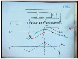
Let us look how this modification takes place. So, again let us consider the developed diagram. This North Pole, this is the South Pole, the brushes at these positions the armature windings are moving in this direction. Let us say this machine is working as a generator in which case we have seen, the induced voltage will be of such a polarity that it will try to oppose the Mary cause which it is due, which means this current will try to produce a flux which will flow from the stature to the rotor therefore, these will be dot whereas, this will be cross. The field flux density wave found we have seen is track is arrow, what about the flux density wave form produced by the armature current. Can be shown that the m m f produced by the armature will be of triangular, this is field flux density wave form. The m m f magneto motive force, which is given in a close path by the current enclosed, will be of triangular open with peaks coinciding with the brush axis.
Natural due to, this is armature m m f at armature, due to this armature m m f there will be a flux which will positive direction which is from stature to the rotor. This flux will have a zero crossing at the pole centers and will have a expected to have a maximum value at the interpolar region, but at the interpolar region the air gap is very large and hence there will be a deep in the interpolar region. And the flux density wave form will actually look somewhat like; this is flux density wave form due to armature winding. So, the resultant flux density wave form will be distorted there will be two prominent effect.
First of all there will be reduction in the flux density wave form on this side of the pole shoe and there will be an increase corresponding increase on the other side. As well as the flux density, wave flux density at the position of the brushes will no longer remain zero, but it will shift by some angle. The resultant flux density wave form will be distorted and will be given by this red line. This distortion of the field flux due to the current flowing into the armature is called armature reaction. Now, what is the effect of, let us see what is the effect of armature reaction in the, what is the effect of armature reaction on the induced voltage and torque and etcetera.
We have seen that the voltage induced in a armature coil depends on the flux per pole. Now, the flux per pole due to the current flowing into the armature is due to the field flux and the armature flux. It is to be noted although the individual armature coils are moving with the armature; however, the pattern of dot and cross currents between the brushes does not change with time. Therefore, the armature m m f and hence the armature flux density wave form are also stationary in space. They do not change, because individual armature passes through the brush, but the pattern between a dot and cross current between two brushes remains always fixed.
So, the armature m m f and the armature flux also remain stationary in space. The armature m m f peak coincides with the brush axis at it 0 is usually at the magnetic axis called the direct axis and therefore, there will be a distortion in the resultant flux. However, if we assume that the magnetic circuit is unsaturated, we see that the net m m f under net armature m m f under one pole is 0. That is the negative m m f at this edge cancels the positive m m f at this edge and hence if the field circuit in linear that is flux density is proportional, flux is proportional to the m m f then there will be no change in the net flux per pole, hence the induce voltage will not change. But in general the machines do not work in the unsaturated region of the magnetization carp. So, if we consider the magnetization, the saturation of the armature and the iron of the d c machine then we arrive at a different picture.
(Refer Slide Time: 21:01)
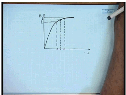
Let us considered the B H curve of the magnetic path of the d c machine, normally for proper utilization of the iron material, the normal operating point due to field flux is already in the saturation zone of the B H characteristics. Now, on which if we apply a positive armature ampere turn under negative ampere turn of same magnitude we find that the change in the flux density are not same. That is increase in the flux density due to increase in the ampere turns is less than the decrease.
Therefore what will happen due to same peak armature ampere turns which is negative on this edge and positive on this edge will not result in same amount of increase and decrease in the flux density wave form. That means, the while on this edge the flux density will reduce by substantial amount which is almost proportional to the A T on the other edge the increase will not be as much. So, the decrease will be more than the increase therefore, there will be in net the magnetization of the field flux that is the flux per pole I p will reduce and hence the induced voltage will also reduced this is one problem.
The other problem is that, we find that, the position of zero crossing of the resultant field wave form, field flux wave form is different from that of the zero crossing position of the field flux alone. The brushes are usually placed at the zero crossing of the field flux, but because of armature reaction the flux, resultant flux density at the position of the brushes is no longer zero, hence the coil that will be connecting to the brushes will not have a zero induce voltage at that time at the moment of commutation. Hence during commutation when we have seen that the coils are shorted the induce voltage will not be zero and there will be circulating current and associated problems, this is one disadvantage of armature reaction.
The other disadvantage is even if this is not the voltage induced in every coil. We have found that discontinuous voltage is proportional to the flux density, because of this increase and decrease in the flux density wave from the instantaneous induced voltage in a coil will be far larger than there average value. Hence what will happen is the adjacent commutated segments will be subjected to a much larger tig voltage which may cause break down of the insulation between the commutated segments therefore, it is necessary to counter the effect of armature reaction in a d c machine. So, for that we need to find out what is the peak of the armature ampere turns. We know there are total e number z number of conductors.
(Refer Slide Time: 27:09)
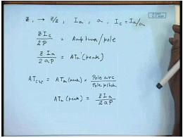
So, z is a total number of conductors in the armature, the total number of turns is z by 2 and if the total armature current is I a and number of parallel paths is a then the I c the conductor equal to I a by a. So, the armature ampere turns can be calculated as z I c and per pole is divided by p. So, this is the armature, this is the, this magnitude that is z I a by 2 a p to armature ampere turns peak. In order to negate the effect of armature reaction, this ampere turns needs to be compensated.
This can be done by putting a, adding another winding to the pole face. And then exciting this winding in series with the armature so that the armature m m f is to some extant canceled by the m m f produced by this incoil. This is called the compensating winding it is a pole face winding which carries a current which is proportional to the armature current. So, how much should be the ampere terns produced by this coil can be easily found out from the formula that ampere turns of the compensating winding should be equal to ampere turns of the peak from the armature into pole arc by pole pitch, where we have seen that, obviously the compensating winding will not be able to completely eliminate the armature reaction m m f, because the pole shoes do not extend over the entire armature surface. In fact this compensating winding will mostly compensate for the flux in the, of the main flux demagnetization effect of the main flux, but it will not be able to compensate all the flux in the interpolar region for that a separate arrangement needs to be used.
(Refer Slide Time: 33:37)
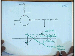
So, the arrangement along with compensating winding can be represented like this, let us, this is the d c machine these are the brushes the compensating winding at to be connected in series with the brush, while the field winding. So, compensating winding is placed on what is called the quadrature of the interpolar axis, q axis of the d c machine while the main flux is on the d axis. Once the compensating winding is in place, it will cancel the armature for mostly the armature m m f flux in the directly under the pole, but it will not compensate completely the m m f at the interpolar region therefore, the armature m m f with compensating winding will look somewhat like this. This was the uncompensated armature ampere turns, this is the extension of the pole arc then ampere turns in this region gets compensated, but not outside this region.
So, the ampere turns produced by the whole face compensating winding would be in opposite direction and we will have a peak value same as this. If this magnitude is A T a peak and the ampere turns produce by the compensating winding will be into pole arc by pole pitch that is. This is pole arc and this is pole pitch therefore, this amount of armature m m f at the interpolar region will still remain uncompensated.
(Refer Slide Time: 39:19)
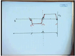
And hence the flux density wave form, so is the flux density wave form due to the field flux. The remaining armature reaction m m f after compensation by the compensating winding will be of this form. Hence there will be small armature m m f flux produced in the interpolar regions and the resultant flux density; I am still show a shift of what you call the magnetic neutral axis that is the flux density. The position where the brushes are normally kept will not be zero, this will give rise to some problem in commutation, which will discuss in more detail in the next class. And we will see how to use interpoles to cancel this remaining ampere turns at the interpolar axis.
If we end this discussion let us look at a practice which is sometimes follow in a d c machine. We have seen that, due to armature reaction the magnetic neutral axis shifts accordingly sometimes the shift is applied to the brushes, that is if we look at the d c machine cross section schematically.
(Refer Slide Time: 43:00)
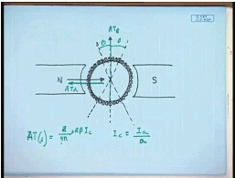
This for simplicity takes only a two pole machine. Originally this is the interpolar axis and brushes are suppose to be in this position; however, if there is a brush shift of beta given then the actual brush position will be this. Now, the current deduction in the armature will change effortingly. This current will be all dot and this will be all cross current.
So, we see that, the armature conductors these are all cross currents these are all dot currents. The field flux from is in this direction; however, the flux produced by the armature conductors in this angle beta is in opposite direction to the field flux this is called the demagnetizing flux due to brush shift. And if there are total z number of conductors that the demagnetizing ampere turns z divided by 4 pi into 2 beta I c that is the A T demagnetizing. So, due to brush shift there will be a demagnetizing ampere turn, that is the total ampere turns, this is the A T demagnetizing and this is the, what is called the cross magnetizing ampere turns.
The rest of the armature conductors will contribute to the cross magnetizing that is the ampere turns that produces a flux align to the quadrature axis while the demagnetizing ampere turns are, ampere turns that produces flux which are align to the direct axis that in the field axis. And are in opposite produces a flux that are in opposite direction to the field flux therefore, if a brush shift is applied then it is necessary that number of filters be modified accordingly in order to counter the effect of demagnetizing ampere turns due to brush shift. And the field number of turns can be the field ampere turns necessary should be equal to the demagnetizing ampere turns produce by brush shift which is given by this formula, where I c equal to I a by ampere the number of parallel paths.
So, in summary we can say that due to the armature reaction is due to the current flowing into the armature winding produces a armature ampere m m f wave form which is triangular in nature. The peak of the triangular wave form is at the quadrature axis where the zero crossing of the ampere turns produce by the armature is the direct axis that is directly under the pole due to this armature reaction m m f. Although the actual armature conductors rotate in space the armature m m f is stationary, because the conduction pattern of current between two brushes does not change with time.
Therefore the armature m m f wave formed and hence the fields produce by the flux density wave form produced by the armature current remains stationary in space. Now, the effect of this armature m m f is that it produces a flux density wave form which has zero crossing under the poles, but its peak are at the interpolar region. But since the interpolar region has larger reluctance, the peak usually occurs somewhat. Before that and hence it tends to strain then the flux density or increase the flux density at one end of the pole shoe while reducing it on the other end. Please note that the end at which the flux density wave form will be increased or reduced will depend on whether the machine is working as a motor or as a generator. And they will be in opposite direction in motoring and generating mode.
Now, if the machine is operating the unsaturated region of the magnetic circuit then the net increase in the flux per pole will not change. And hence there will be no change in the induced e m f; however, most practical machines are not operated in the unsaturated region of the magnetic circuit, because of saturation the decrease in the field flux density will be more than its increase. And hence there will be a net decrease in the flux per pole and due to armature reaction the induced e m f will reduce not only this we have seen that due to armature reaction there will be flux density at the interpolar region. While the flux density due to the field flux alone is 0 at the interpolar axis. And hence the flux density at the geometric neutral axis where the brushes are place will not be 0, this will create problem during commutation.
Hence it is necessary to compensate for the armature reaction flux produce by the armature current. This is normally done by using a compensating winding. A compensating winding is a pole face winding and connected in series with the brushes; however, a compensating winding can compensate for the armature ampere turns which are directly under the pole shoe. But as the pole show does not extant over the entire armature periphery the compensating winding can compensate only a part of the armature reaction flux. The armature reaction m m f directly under the interpolar axis cannot be compensate by the compensating winding for this purpose a interpole is used the effect of the flux density at the interpolar axis. And how to compensate it using interpols will be discuss in the next class.
Thank you.