Free Body Diagram in 2D | Engineering Mechanics for Mechanical Engineering PDF Download

When a body is in equilibrium, the resultant of all forces acting on it is zero. Thus, the resultant force R and the resultant couple M are both zero, and we have the equilibrium equations
R = ΣF = 0 M = ΣM = 0(3/1)
These requirements are both necessary and sufficient conditions for equilibrium.
Free Body diagram:
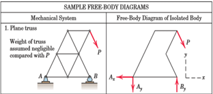
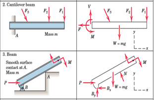
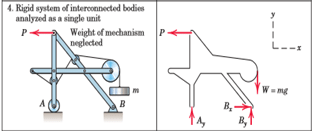
Before we apply Eqs. 3/1, we must define unambiguously the particular body or mechanical system to be analyzed and represent clearly and completely all forces acting on the body. Omission of a force which acts on the body in question, or inclusion of a force which does not act on the body, will give erroneous results. A mechanical system is defined as a body or group of bodies which can be conceptually isolated from all other bodies. A system may be a single body or a combination of connected bodies. The bodies may be rigid or nonrigid. The system may also be an identifiable fluid mass, either liquid or gas, or a combination of fluids and solids. In statics we study primarily forces which act on rigid bodies at rest, although we also study forces acting on fluids in equilibrium. Once we decide which body or combination of bodies to analyze, we then treat this body or combination as a single body isolated from all surrounding bodies. This isolation is accomplished by means of the free-body diagram, which is a diagrammatic representation of the isolated system treated as a single body. The diagram shows all forces applied to the system by mechanical contact with other bodies, which are imagined to be removed. If appreciable body forces are present, such as gravitational or magnetic attraction, then these forces must also be shown on the free-body diagram of the isolated system. Only after such a diagram has been carefully drawn should the equilibrium equations be written. Because of its critical importance, we emphasize here that
Note: The free-body diagram is the most important single step in the solution of problems in mechanics.
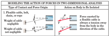
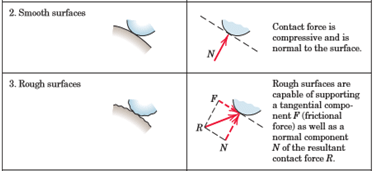
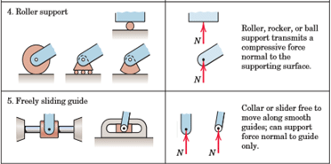
Before attempting to draw a free-body diagram, we must recall the basic characteristics of force. These characteristics were described in Art. 2/2, with primary attention focused on the vector properties of force. Forces can be applied either by direct physical contact or by remote action. Forces can be either internal or external to the system under consideration. Application of force is accompanied by reactive force, and both applied and reactive forces may be either concentrated or distributed. The principle of transmissibility permits the treatment of force as a sliding vector as far as its external effects on a rigid body are concerned. We will now use these force characteristics to develop conceptual models of isolated mechanical systems. These models enable us towrite the appropriate equations of equilibrium, which can then be analyzed.
|
23 videos|86 docs|44 tests
|
FAQs on Free Body Diagram in 2D - Engineering Mechanics for Mechanical Engineering
| 1. What is a free body diagram in 2D? |  |
| 2. How is a free body diagram created in 2D? | |
| 3. Why are free body diagrams important in 2D analysis? | |
| 4. What are the key components of a free body diagram in 2D? | |
| 5. How can free body diagrams in 2D be used to solve problems? | |


Sample Paper
,Exam
,past year papers
,practice quizzes
,Viva Questions
,Previous Year Questions with Solutions
,Free
,Free Body Diagram in 2D | Engineering Mechanics for Mechanical Engineering
,Summary
,Objective type Questions
,Free Body Diagram in 2D | Engineering Mechanics for Mechanical Engineering
,Extra Questions
,video lectures
,Semester Notes
,study material
,shortcuts and tricks
,mock tests for examination
,Free Body Diagram in 2D | Engineering Mechanics for Mechanical Engineering
,ppt
,Important questions
,MCQs
,


Free Body Diagram in 2D Free PDF Download
Importance of Free Body Diagram in 2D
Free Body Diagram in 2D Notes
Free Body Diagram in 2D Mechanical Engineering Questions
Study Free Body Diagram in 2D on the App
|
© EduRev
|
Education Revolution
|


|


