Civil Engineering (CE) Exam > Civil Engineering (CE) Notes > Engineering Mechanics > Resultant of a General Distributed Force System
Resultant of a General Distributed Force System | Engineering Mechanics - Civil Engineering (CE) PDF Download

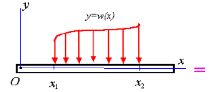
Equivalent force systems: Distributed loads
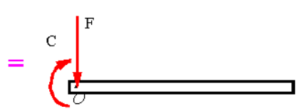
Replacing distributed loads by a resultant load and resultant couple applied at a given point O :
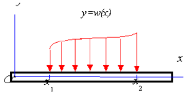
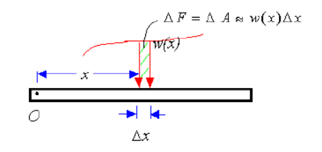
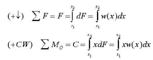
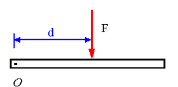
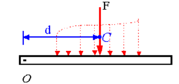
Replacing a distributed load by single resultant load:
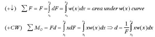
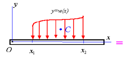
Note: Since the equation for d is the same as that for determining the centroid of the area under the w(x) curve, it follows that F must pass through the centroid of the area under the curve w(x).
The document Resultant of a General Distributed Force System | Engineering Mechanics - Civil Engineering (CE) is a part of the Civil Engineering (CE) Course Engineering Mechanics.
All you need of Civil Engineering (CE) at this link: Civil Engineering (CE)
|
24 videos|69 docs|53 tests
|
FAQs on Resultant of a General Distributed Force System - Engineering Mechanics - Civil Engineering (CE)
| 1. What is a distributed force system? |  |
A distributed force system refers to a collection of forces that act over an area rather than at a single point. These forces are typically spread out or distributed along a surface, resulting in a varying intensity or magnitude across the area.
| 2. How is the resultant of a general distributed force system determined? | |
To determine the resultant of a general distributed force system, the forces need to be integrated over the area they act upon. This integration involves calculating the magnitude and direction of each force at different points on the area and summing them up. The resultant force is then found by considering the combined effect of all the individual forces.
| 3. Can you provide an example of a general distributed force system? | |
Certainly! One example of a general distributed force system is the pressure distribution on the surface of a dam due to water. The pressure varies across the surface, with higher magnitudes near the bottom and lower magnitudes near the top. By integrating the pressure forces over the surface, we can determine the resultant force acting on the dam.
| 4. What are some applications of analyzing general distributed force systems? | |
Analyzing general distributed force systems is crucial in various engineering fields. Some common applications include analyzing the wind loads on buildings, calculating the hydrostatic forces on submerged structures, determining the stress distribution in materials subjected to distributed loads, and evaluating the stability of structures under the influence of distributed forces.
| 5. How does the complexity of a distributed force system affect the analysis? | |
The complexity of a distributed force system can significantly impact the analysis process. As the system becomes more complex, with a larger number of forces and varying magnitudes and directions, the calculations become more intricate. Advanced mathematical techniques, such as integration and vector calculus, are often required to accurately determine the resultant force and its effects on structures or materials.
About this Document

4.75/5
Rating

Oct 14, 2025
Last updated
Related Exams
Document Description: Resultant of a General Distributed Force System for Civil Engineering (CE) 2025 is part of Engineering Mechanics preparation.
The notes and questions for Resultant of a General Distributed Force System have been prepared according to the Civil Engineering (CE) exam syllabus. Information about Resultant of a General Distributed Force System covers topics
like and Resultant of a General Distributed Force System Example, for Civil Engineering (CE) 2025 Exam. Find important definitions, questions, notes, meanings, examples, exercises and tests below for Resultant of a General Distributed Force System.
Introduction of Resultant of a General Distributed Force System in English is available as part of our Engineering Mechanics
for Civil Engineering (CE) & Resultant of a General Distributed Force System in Hindi for Engineering Mechanics course.
Download more important topics related with notes, lectures and mock test series for Civil Engineering (CE)
Exam by signing up for free. Civil Engineering (CE): Resultant of a General Distributed Force System | Engineering Mechanics - Civil Engineering (CE)
Description
Full syllabus notes, lecture & questions for Resultant of a General Distributed Force System | Engineering Mechanics - Civil Engineering (CE) - Civil Engineering (CE) | Plus excerises question with solution to help you revise complete syllabus for Engineering Mechanics | Best notes, free PDF download
Information about Resultant of a General Distributed Force System
In this doc you can find the meaning of Resultant of a General Distributed Force System defined & explained in the simplest way possible. Besides explaining types of
Resultant of a General Distributed Force System theory, EduRev gives you an ample number of questions to practice Resultant of a General Distributed Force System tests, examples and also practice Civil Engineering (CE)
tests

Related Searches
Important questions
,Summary
,Extra Questions
,study material
,Free
,Viva Questions
,ppt
,Sample Paper
,Resultant of a General Distributed Force System | Engineering Mechanics - Civil Engineering (CE)
,video lectures
,Semester Notes
,Exam
,shortcuts and tricks
,Resultant of a General Distributed Force System | Engineering Mechanics - Civil Engineering (CE)
,MCQs
,past year papers
,Resultant of a General Distributed Force System | Engineering Mechanics - Civil Engineering (CE)
,practice quizzes
,Previous Year Questions with Solutions
,Objective type Questions
,mock tests for examination
;


Additional Information about Resultant of a General Distributed Force System for Civil Engineering (CE) Preparation
Resultant of a General Distributed Force System Free PDF Download
The Resultant of a General Distributed Force System is an invaluable resource that delves deep into the core of the Civil Engineering (CE) exam.
These study notes are curated by experts and cover all the essential topics and concepts, making your preparation more efficient and effective.
With the help of these notes, you can grasp complex subjects quickly, revise important points easily,
and reinforce your understanding of key concepts. The study notes are presented in a concise and easy-to-understand manner,
allowing you to optimize your learning process. Whether you're looking for best-recommended books, sample papers, study material,
or toppers' notes, this PDF has got you covered. Download the Resultant of a General Distributed Force System now and kickstart your journey towards success in the Civil Engineering (CE) exam.
Importance of Resultant of a General Distributed Force System
The importance of Resultant of a General Distributed Force System cannot be overstated, especially for Civil Engineering (CE) aspirants.
This document holds the key to success in the Civil Engineering (CE) exam.
It offers a detailed understanding of the concept, providing invaluable insights into the topic.
By knowing the concepts well in advance, students can plan their preparation effectively.
Utilize this indispensable guide for a well-rounded preparation and achieve your desired results.
Resultant of a General Distributed Force System Notes
Resultant of a General Distributed Force System Notes offer in-depth insights into the specific topic to help you master it with ease.
This comprehensive document covers all aspects related to Resultant of a General Distributed Force System.
It includes detailed information about the exam syllabus, recommended books, and study materials for a well-rounded preparation.
Practice papers and question papers enable you to assess your progress effectively.
Additionally, the paper analysis provides valuable tips for tackling the exam strategically.
Access to Toppers' notes gives you an edge in understanding complex concepts.
Whether you're a beginner or aiming for advanced proficiency, Resultant of a General Distributed Force System Notes on EduRev are your ultimate resource for success.
Resultant of a General Distributed Force System Civil Engineering (CE) Questions
The "Resultant of a General Distributed Force System Civil Engineering (CE) Questions" guide is a valuable resource for all aspiring students preparing for the
Civil Engineering (CE) exam. It focuses on providing a wide range of practice questions to help students gauge
their understanding of the exam topics. These questions cover the entire syllabus, ensuring comprehensive preparation.
The guide includes previous years' question papers for students to familiarize themselves with the exam's format and difficulty level.
Additionally, it offers subject-specific question banks, allowing students to focus on weak areas and improve their performance.
Study Resultant of a General Distributed Force System on the App
Students of Civil Engineering (CE) can study Resultant of a General Distributed Force System alongwith tests & analysis from the EduRev app,
which will help them while preparing for their exam. Apart from the Resultant of a General Distributed Force System,
students can also utilize the EduRev App for other study materials such as previous year question papers, syllabus, important questions, etc.
The EduRev App will make your learning easier as you can access it from anywhere you want.
The content of Resultant of a General Distributed Force System is prepared as per the latest Civil Engineering (CE) syllabus.
|
© EduRev
|
Education Revolution
|


|


Signup to see your scores
go up within 7 days!
Access 1000+ FREE Docs, Videos and Tests
Takes less than 10 seconds to signup