Introduction on Synchronous Machines | Electrical Engineering SSC JE (Technical) - Electrical Engineering (EE) PDF Download
| Table of contents |

|
| Construction of Synchronous Machines |

|
| Classification of Synchronous Machines according to the form of Excitation |

|
| Advantages of Stationary Armature |

|
| Frequently Asked Questions (FAQs) |

|
A synchronous machine is an ac rotating machine whose speed under steady state condition is proportional to the frequency of the current in its armature.
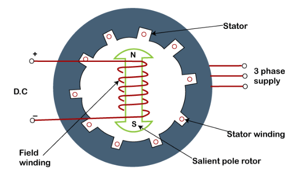 Diagram of Synchronous Machine
- The magnetic field created by the stator currents rotates at the synchronous speed ,and that created by the field current on the rotor is rotating at the synchronous speed also, and a steady torque results. So, these machines are called synchronous machines because they operate at constant speeds and constant frequencies under steady state conditions.
Synchronous machines are commonly used as generators especially for large power systems, such as turbine generators and hydroelectric generators in the grid power supply.
Because the rotor speed is equal to the synchronous speed of stator magnetic field, synchronous motors can be used in situations where constant speed drive is required.
Since the reactive power generated by a synchronous machine can be adjusted by controlling the magnitude of the rotor field current, unloaded synchronous machines are also often installed in power systems for power factor correction or for control of reactive kVA flow. Such machines, known as synchronous condensers, and may be more economical in the large sizes than static capacitors.
The bulk of electric power for everyday use is produced by polyphase synchronous generators (alternators), which are the largest single-unit electric machines in production.
For instance, synchronous generators with power ratings of several hundred megavolt-amperes (MVA) are fairly common, and it is expected that machines of several thousand megavolt- amperes will be in use in the near future.
Like most rotating machines, synchronous machines are capable of operating both as a motor and as a generator. They are used as motors in constant-speed drives, and where a variable-speed drive is required, a synchronous motor is used with an appropriate frequency changer such as an inverter.
As generators, several synchronous machines often operate in parallel, as in a power station. While operating in parallel, the generators share the load with each other; at a given time one of the generators may not carry any load. In such a case, instead of shutting down the generator, it is allowed to "float" on the line as a synchronous motor on no-load.
Construction of Synchronous Machines
The synchronous machine has 3 phase winding on the stator and a d.c. field winding on the rotor.
1. Stator
- Stator is the stationary part of the machine and is built up of sheet-steel laminations having slots on its inner periphery.
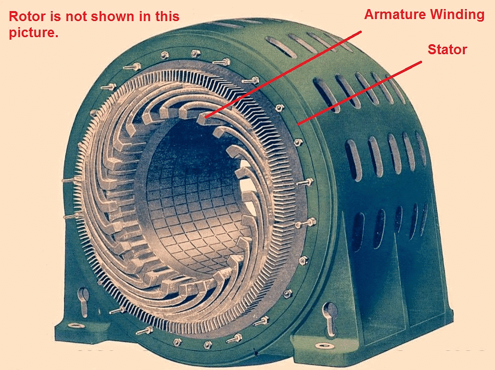 Showing Stator
 - A 3-phase winding is placed in these slots.
- The armature winding is always connected in star and the neutral is connected to ground.
2. Rotor
The rotor carries a field winding which is supplied with direct current through two slip rings by a separate d.c. source.
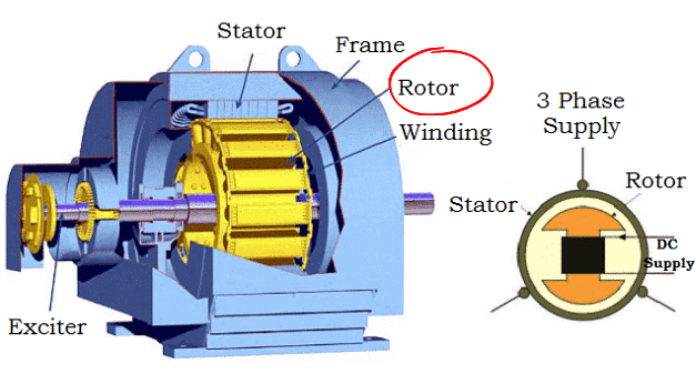
Rotor construction is of two types:
(i) Salient (or projecting) pole type
(ii) Non-salient (or cylindrical) pole type
Salient Pole Type
In this type, salient or projecting poles are mounted on a large circular steel frame which is fixed to the shaft of the alternator as shown in Figure below:
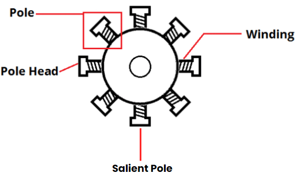 Salient Pole Rotor
- The individual field pole windings are connected in series in such a way that when the field winding is energized by the d.c. exciter, adjacent poles have opposite polarities.
- Low-speed alternators (120 - 400 r.p.m.) such as those driven by water turbines have salient pole .
Type rotors due to the following reasons:
(a) The salient field poles would cause an excessive windage loss if driven at high speed and would tend to produce noise.
(b) Salient-pole construction cannot be made strong enough to withstand the mechanical stresses to which they may be subjected at higher speeds.
- Since a frequency of 50 Hz is required, we must use a large number of poles on the rotor of slow-speed alternators.
- Low-speed rotors always possess a large diameter to provide the necessary space for the poles.
- Consequently, salient-pole type rotors have large diameters and short axial lengths.
(ii) Non-Salient Pole (cylindrical) type
- In this type, the rotor is made of smooth solid forged-steel radial cylinder having a number of slots along the outer periphery.
- The field windings are embedded in these slots and are connected in series to the slip rings through which they are energized by the d.c. exciter.
- The regions forming the poles are usually left unslotted as shown in Figure below.
- It is clear that the poles formed are non-salient i.e., they do not project out from the rotor surface.

High-speed alternators (1500 or 3000 r.p.m.) are driven by steam turbines and use non-salient type rotors due to the following reasons:
(a) This type of construction has mechanical robustness and gives noiseless operation at high speeds.
(b) The flux distribution around the periphery is nearly a sine wave and hence a better e.m.f. waveform is obtained than in the case of salient-pole type.
- Since steam turbines run at high speed and a frequency of 50 Hz is required, we need a small number of poles on the rotor of high-speed alternators (also called turboalternators).
- We can use not less than 2 poles and this fixes the highest possible speed. For a frequency of 50 Hz, it is 3000 r.p.m.
- The next lower speed is 1500 r.p.m. for a 4-pole machine.
- Consequently, turboalternators possess 2 or 4 poles and have small diameters and very long axial lengths.
Classification of Synchronous Machines according to the form of Excitation
1. Brushes Excitation Systems
- The field structure is usually the rotating member of a synchronous machine and is supplied with a dc-excited winding to produce the magnetic flux.
- This dc excitation may be provided by a self-excited dc generator mounted on the same shaft as the rotor of the synchronous machine. This dc generator is known as exciter.
- The direct current generated inside exciter is fed to the synchronous machine field winding.
- In slow-speed machines with large ratings, such as hydroelectric generators, the exciter may not be self-excited. Instead, a pilot exciter, which may be self-excited or may have a permanent magnet, activates the main exciter.
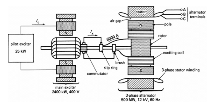 Brushes excitation system for a Synchronous Machine
2. Brushless Systems
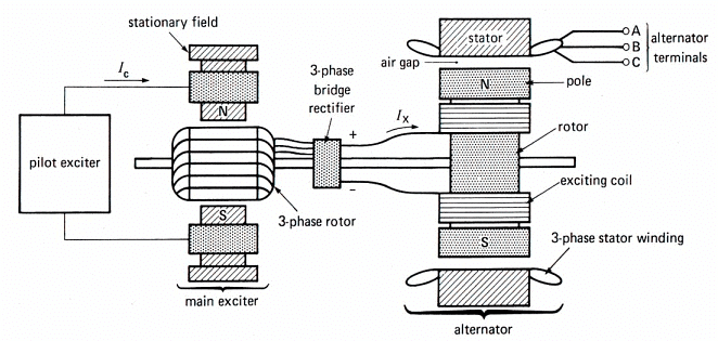 Brushless excitation system for a Synchronous Machine
3. Static Systems
- This type of excitation is widely used in small size alternators, in which portion of the AC from each phase of synchronous generator is fed back to the field winding as a DC excitation through a system of transformer, rectifiers and reactors.
- External source of a DC is necessary for initial excitation of the field windings.
Advantages of Stationary Armature
This arrangement has the following advantages:
(i) It is easier to insulate stationary winding for high voltages , because they are not subjected to centrifugal forces .
(ii) The stationary 3-phase armature can be directly connected to load without going through large, unreliable slip rings and brushes.
(iii) Only two slip rings are required for d.c. supply to the field winding on the rotor. Since the exciting current is small, the slip rings and brush gear required are of light construction.
(iv) Due to simple and robust construction of the rotor, higher speed of rotating d.c. field is possible. This increases the output obtainable from a machine of given dimensions.
Cooling
- Because synchronous machines are often built in extremely large sizes, they are designed to carry very large currents. A typical armature current density may be of the order of 10 A/mm2 in a well-designed machine.
- Also, the magnetic loading of the core is such that it reaches saturation in many regions.
- The severe electric and magnetic loadings in a synchronous machine produce heat that must be appropriately dissipated.
- Thus the manner in which the active parts of a machine are cooled determines its overall physical structures.
- In addition to air, some of the coolants used in synchronous machines include water, hydrogen, and helium.
Damper Bars
- So far we have mentioned only two electrical windings of a synchronous machine:
1. Three-phase armature winding
2. Field winding - We also pointed out that, under steady state, the machine runs at a constant speed, that is, at synchronous speed. However, like other electric machines, a synchronous machine undergoes transients during starting and abnormal conditions.
- During transients, the rotor may undergo mechanical oscillations and its speed deviates from the synchronous speed, which is an undesirable phenomenon.
- To overcome this, an additional set of windings, resembling the cage of an induction motor, is mounted on the rotor.
- When the rotor speed is different from the synchronous speed, currents are induced in the damper windings.
- The damper winding acts like the cage rotor of an induction motor, producing a torque to restore the synchronous speed.
- Also, the damper bars provide a means of starting to the synchronous motors, which is otherwise not selfstarting. Figure given below shows the damper bars on a salient rotors
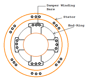 Salient Pole Rotor showing the field winding and damper bars
Differences between three phase induction machines and synchronous machine
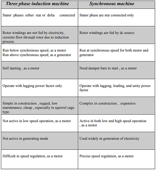
Frequently Asked Questions (FAQs)
Q.1. What is synchronous condenser?
An over-excited synchronous motor under no load ,used for the improvement of power factor is called as synchronous condenser because, like a capacitor it takes a leading current.
Q.2. State the characteristic features of synchronous motor.
- The motor is not inherently self starting.
- The speed of operation is always in synchronous with the supply frequency irrespective of load conditions.
- The motor is capable of operating at any power factor.
Q.3. In what way synchronous motor is different from other motors?
- All dc and ac motors work on the same principle.
- Synchronous motor operates due to magnetic locking taking place between stator and rotor magnetic fields.
Q.4. Why a synchronous motor is a constant speed motor?
Synchronous motor work on the principle of force developed due to the magnetic attraction established between the rotating magnetic field and the main pole feed. Since the speed of rotating magnetic field is directly proportional to frequency the motor operates at constant speed.
Q.5. How the synchronous motor can be used as s synchronous condenser?
Synchronous motor is operated on over excitation so as to draw leading reactive current and power from the supply lines. This compensates the lagging current and power requirement of the load making the system power factor to be come unity. The motor does the job of capacitors and hence called as synchronous condenser.
|
23 videos|94 docs|42 tests
|
FAQs on Introduction on Synchronous Machines - Electrical Engineering SSC JE (Technical) - Electrical Engineering (EE)
| 1. What is the construction of synchronous machines? |  |
| 2. How are synchronous machines classified according to the form of excitation? |  |
| 3. What are the advantages of a stationary armature in synchronous machines? |  |
| 4. How does the excitation of synchronous machines affect their operation? |  |
| 5. What are the main differences between separately excited and self-excited synchronous machines? |  |


