Synchronous Machine Armature Windings - 2 | Electrical Engineering SSC JE (Technical) - Electrical Engineering (EE) PDF Download

Frequency of an A.C. Synchronous Generator
Commercial ac synchronous generators have many poles and may rotate at various speeds, either as alternators or as synchronous or induction motors.Eqn. 13 was derived for a two-pole device in which the generated EMF in the stationary armature winding changes direction every half-revolution of the two-pole rotor. One complete revolution will produce one complete positive and negative pulse each cycle. The frequency in cycles per second (Hz) will, as stated previously, depend directly on the speed or number of revolutions per second (rpm/60) of the rotating field.
If the ac synchronous generator has multiple poles (having, say, two, four, six, or eight poles...), then for a speed of one revolution per second (1 rpm/60), the frequency per revolution will be one, two, three, or four ..., cycles per revolution, respectively. The frequency per revolution, is therefore, equal to the number of pairs of poles. Since the frequency depends directly on the speed (rpm/60) and also on the number of pairs of poles (P/2), we may combine these into a single equation in which
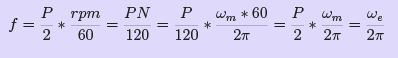 (18)
(18)
where
P is the number of poles
N is the speed in rpm (rev/min)
f is. the frequency in hertz
ωm is the speed in radians per second (rad/s)
ωe is the speed electrical radians per second.
Constructional Details of Rotor
As stated earlier the field windings are provided in the rotor or the rotating member of the synchronous machine. Basically there are two general classifications for large 3 phase synchronous generators ——cylindrical rotor and salient-pole rotor - .
The cylindrical-rotor construction is peculiar to synchronous generators driven by steam turbines and which are also known as turbo alternators or turbine generators. Steam turbines operate at relatively high speeds, 1500 and 3000 rpm being common for 50 Hz, accounting for the cylindrical-rotor construction, which because of its compactness readily withstands the centrifugal forces developed in the large sizes at those speeds. In addition the smoothness of the rotor contour makes for reduced windage losses and for quiet operation.
Salient-pole rotors are used in low-speed synchronous generators such as those driven by water wheels. They are also used in synchronous motors. Because of their low speeds salient-pole generators require a large number of poles as, for example, 60 poles for a 100-rpm 50 Hz generator.
Fig. 14 illustrates two and four pole cylindrical rotors along with a developed view of the field winding for one pair of poles. One pole and its associated field coil of a salient-pole rotor is shown in fig. 14.The stator slots in which the armature winding is embedded are not shown for reasons of simplicity. The approximate path taken by the field flux, not including leakage flux, is indicated by the dashed lines in Fig. 14. The field coils in Fig. 14 are represented by filaments but actually (except for the insulation between turns and between the coil sides and the slot) practically fill the slot more nearly in keeping with fig. 15.
The stepped curve in fig. 15. represents the waveform of the mmf produced by the distributed field winding if the slots are assumed to be completely filled by the copper in the coil sides instead of containing current filaments. The sinusoid indicated by the dashed line in fig. 15 represents approximately the fundamental component of the mmf wave.
The air gap in cylindrical-rotor machines is practically of uniform length except for the slots in the rotor and in the stator, and when the effect of the slots and the tangential component of H, which is quite small for the low ratio of air-gap length to the arc subtended by one pole in conventional machines, are neglected, the stepped mmf wave in fig. 15 produces a flux-density space wave in which the corners of the steps are rounded due to fringing. The flux density wave form is therefore more nearly sinusoidal than the mmf waveform when the effect of the slots is neglected. However, saturation of the iron in the region of maximum mmf tends to flatten the top of the flux-density wave.
Excitation Systems for Synchronous Machines
A number of arrangements for supplying direct current to the fields of synchronous machines have come into use. Adjustments in the field current may be automatic or manual depending upon the complexity and the requirements of the power system to which the generator is connected.
Excitation systems are usually 125 V up to ratings of 50kW with higher voltages for the larger ratings. The usual source of power is a direct-connected exciter, motor- generator
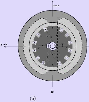
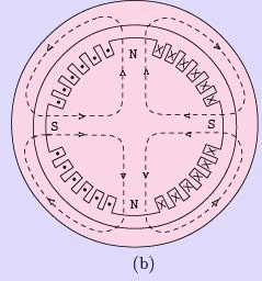
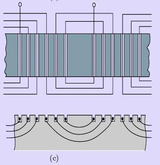
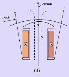
Figure 14: Synchronous machines with stator slots and armature windings omitted (a)Twopole cylindrical rotor, (b) Four-pole cylindrical rotor, (c) Developed view of two pole cylindrical rotor field structure, (d) Salient pole and field coil
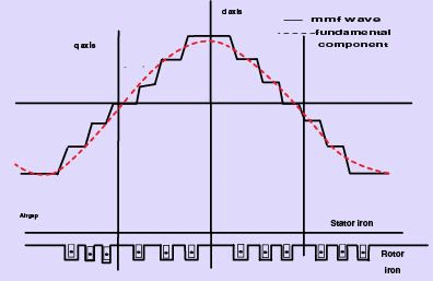
Figure 15: Cylindrical rotor mmf wave and its fundamental of a synchronous machine
set, rectifier, or battery. A common excitation system in which a conventional dc shunt generator mounted on the shaft of the synchronous machine furnishes the field excitation is shown in Fig. 16. The output of the exciter (i.e., the field current of the synchronous machine) is varied by adjusting the exciter field rheostat. A somewhat more complex system that makes use of a pilot exciter—- a compound dc generator—- also mounted on the generator shaft, which in turn excites the field of the main exciter, is shown in Fig. 16. This arrangement makes for greater rapidity of response, a feature that is important in the case of synchronous generators when there are disturbances on the system to which the generator is connected. In some installations a separate motor-driven exciter furnishes the excitation.
An induction motor is used instead of a synchronous motor because in a severe system disturbance a synchronous motor may pullout of synchronism with the system. In addition, a large flywheel is used to carry the exciter through short periods of severely reduced system voltage.
Brushless Excitation System
The brushless excitation system eliminates the usual commutator, collector rings, and brushes. One arrangement in which a permanent magnet pilot exciter, an ac main exciter, and a rotating rectifier are mounted on the same shaft as the field of the ac turbogenerator is shown in Fig. 17. The permanent magnet pilot excitor has a stationary armature and a rotating permanent magnetic field. It feeds 400 Hz, three-phase power to a regulator, which in turn supplies regulated dc power to the stationary field of a rotating-armature ac exciter, The
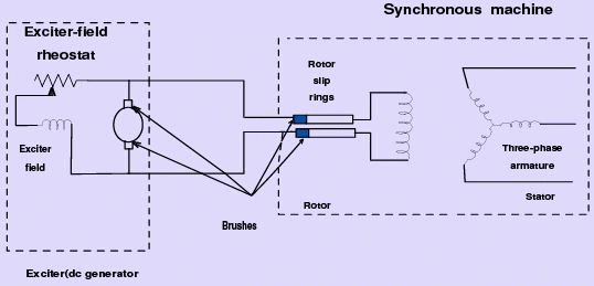
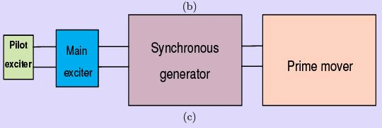
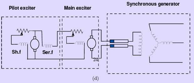

Figure 17: Brushless excitation system
output of the ac exciter is rectified by diodes and delivered to the field of the turbo generator.
Brush less excitation systems have been also used extensively in the much smaller generators employed in aircraft applications where reduced atmospheric pressure intensifies problems of brush deterioration. Because of their mechanical simplicity, such systems lend themselves to military and other applications that involve moderate amounts of power.
The Action of the Synchronous Machine
Just like the DC generator, the behaviour of a Synchronous generator connected to an external load is not the same as at no-load. In order to understand the action of the Synchronous machine when it is loaded, let us take a look at the flux distributions in the machine when the armature also carries a current. Unlike in the DC machine here the current peak and the emf peak will not occur in the same coil due to the effect of the power factor (pf ) of the load. In other words the current and the induced emf will be at their peaks in the same coil only for upf loads. For zero power factor (zpf )(lagging) loads, the current reaches its peak in a coil which falls behind that coil wherein the induced emf is at its peak by nearly 90 electrical degrees or half a pole-pitch. Likewise for zero power factor (zpf )(leading) loads, the current reaches its peak in a coil which is ahead of that coil wherein the induced emf is at its peak by nearly 90 electrical degrees or half a pole-pitch. For simplicity, let us assume the resistance and leakage reactance of the stator windings to be negligible. Let us also assume the magnetic circuit to be linear i.e. the flux in the magnetic circuit is deemed to be proportional to the resultant ampere-turns - in other words we assume that there is no saturation of the magnetic core. Thus the e.m.f. induced is the same as the terminal voltage, and the phase-angle between current and e.m.f. is determined only by the power factor (pf ) of the external load connected to the synchronous generator.
Armature Reaction
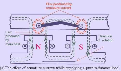
In order to understand more clearly let us consider a sketch of a stretched-out synchronous machine shown in Fig. 18(a) which shows the development of a fixed stator car-
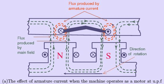
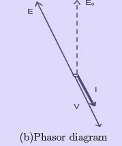
Figure 19: Stretched out synchronous motor
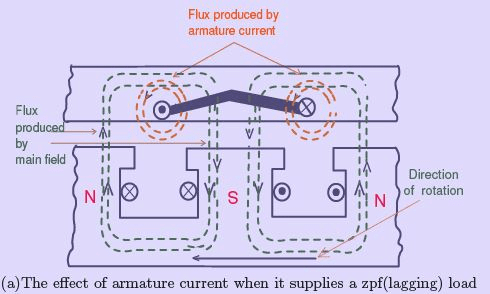
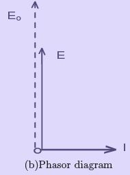
Figure 20: Stretched out synchronous generator
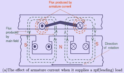
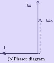
Figure 21: Stretched out synchronous generator
rying armature windings, and a rotor carrying field windings and capable of rotation within it. The directions of the currents and the flux distribution are as shown in Fig. 18(a), when the emf induced in the stator coils is the maximum. The coil links no resultant flux but is in the position of greatest rate of change of flux. The coil position shown is also that for maximum current when the current is in phase with the voltage: i.e for a pure resistive load.
The current in the coil has no effect on the total flux per pole, but causes a strengthening on one side and a weakening on the other side of the pole shoes. Thus the armature conductors find themselves in the circumstances illustrated in Fig. 19, and a torque is produced by the interaction of the main flux φm with the current in the conductors. The torque thus produced is seen to be opposed to the direction of motion of the rotor - the force on the conductors is such as to push them to the left and by reaction to push the rotor to the right (as the armature coils are stationary). The rotor is rotated by a prime mover against this reaction, so that the electrical power, the product E I , is produced by virtue of the supply of a corresponding mechanical power. Thus it is evident from the distortion of the main flux distribution that electrical energy is converted from mechanical energy and the machine operates as a generator. An unidirectional torque is maintained as the stator conductors cut N-Pole and S-Pole fluxes alternately resulting in alternating emfs at a frequency equal to the number of pole-pairs passed per second and the currents also alternate with the emf.
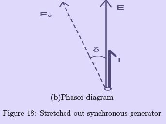
The assumption that the conditions shown in Fig. 18(a) represent co-phasal emf and current is not quite true. The strengthening of the resultant flux on the right of the poles and an equivalent amount of weakening on the left effectively shift the main field flux axis against the direction of rotation, so that the actual e.m.f. E induced in the armature winding is an angle δ behind the position E0 that it would occupy if the flux were undistorted as shown in the adjacent phasor diagram Fig. 18(b) pertaining to this condition of operation. Thus the effect of a resistive (unit power factor (upf )) load connected to a synchronous generator is to shift the main field flux axis due to what is known as cross-magnetization.
The action of a synchronous machine operating as a motor at unit power factor (upf ) is shown in Fig. 19(a). Just like a DC motor, a synchronous motor also requires an externally-applied voltage V in order to circulate in it a current in opposition to the induced e.m.f. E. The coil is shown in the position of maximum induced emf and current, but the current is oppositely directed to that shown in Fig. 18(a). Again the m.m.f. of the coil does not affect the total flux in the common magnetic circuit, but distorts the distribution in such a way as to produce a torque in the same direction as the motion. The machine is a motor by virtue of the electrical input VI causing a torque in the direction of motion.
The flux distortion causes a shift of the flux axis across the poles, so that the actual e.m.f.
E is an angle δ ahead of the position E0 that it would occupy if the flux were undistorted as shown in the adjacent phasor diagram Fig. 19(b), pertaining to this condition of operation.
Next let us consider this generator to be connected to a purely inductive load so that the current I in the coils lags behind the e.m.f. E by 90 electrical degrees i.e. corresponding to a quarter-period, in time scale. Since the coil-position in Fig. 18(a) or Fig. 19(a) represents that for maximum e.m.f., the poles would have moved through half a pole-pitch before the current in the coil has reached a maximum as shown in Fig. 20(a). As seen from this figure it is obvious that the ampere-turns of the stator coils are now in direct opposition to those on the pole, thereby reducing the total flux and e.m.f. Since the stator and rotor ampere-turns act in the same direction, there is no flux-distortion, no torque, and hence no additional mechanical power. This circumstance is in accordance with the fact that there is also no electrical power output as E and I are in phase quadrature, as shown in Fig. 20(b). The phasor Eo represents the e,m.f. with no demagnetizing armature current, emphasizing the reduction in e.m.f. due to the reduced flux.
Likewise, when this generator is connected to a purely capacitive load i.e the current I in the coil leads the emf E by 90 electrical degrees, the conditions are such that the armature AT and the field AT will be assisting each other as shown in Fig. 21.
When the generator supplies a load at any other power factor intermediate between unity and zero, a combination of cross- and direct-magnetization is produced on the magnetic circuit by the armature current. The cross-magnetization is distorting and torque-producing as in Fig. 18; the direct-magnetization decreases (for lagging currents) or increases (for leading currents) the ampere-turns acting on the magnetic circuit as in Fig. 20 and Fig. 21, affecting the main flux and the e.m.f. accordingly.
For a motor the torque is reversed on account of the current reversal, and the directmagnetizing effect is assisting the field ampere-turns for lagging currents. The action of the armature ampere-turns as described above is called armature-reaction. The effect of the armature reaction has a far-reaching influence on the performance of the synchronous motor, particularly as regards the power factor at which it operates and the amount of field excitation that it requires.
Behaviour of a loaded synchronous generator
The simple working of the synchronous machine can be summed up as follows: A synchronous machine driven as a generator produces e.m.f.’s in its armature windings at a frequency f = np. These e.m.f.’s when applied to normal circuits produce currents of the same frequency. Depending on the p.f of the load, field distortion is produced, generating a mechanical torque and demanding an input of mechanical energy to satisfy the electrical output. As the stator currents change direction in the same time as they come from one magnetic polarity to the next, the torque is unidirectional. The torque of individual phases is pulsating just like in a single-phase induction machine - but the torque of a three-phase machine is constant for balanced loads.
For the cylindrical rotor machine the fundamental armature reaction can be more
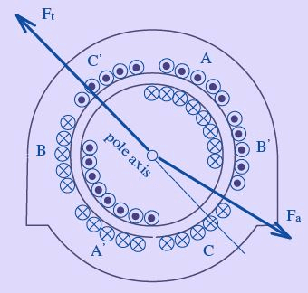
Figure 22: Synchronous generator supplying a lagging pf load
convincingly divided into cross-magnetizing and direct-magnetizing components, since the uniform air-gap permits sinusoidal m.m.f s to produce more or less sinusoidal fluxes. Fig. 22 shows a machine with two poles and the currents in the three-phase armature winding produce a reaction field having a sinusoidally-distributed fundamental component and an axis coincident, for the instant considered, with that of one phase such as A − A′ . The rotor windings, energized by direct current, give also an approximately sinusoidal rotor m.m.f. distribution. The machine is shown in operation as a generator supplying a lagging current.
The relation of the armature reaction m.m.f. Fa to the field m.m.f. Ft is shown in Fig. 23.
The Fa sine wave is resolved into the components Faq corresponding to the cross-component and Fad corresponding to the direct-component, which in this case demagnetizes in accordance with Fig. 20. Fad acts in direct opposition to Ft and reduces the effective m.m.f. acting round the normal magnetic circuit. Faq shifts the axis of the resultant m.m.f. (and flux) backward against the direction of rotation of the field system.
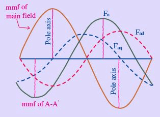
Figure 23: Sinusoidal distribution of the components of armature reaction in a synchronous generator
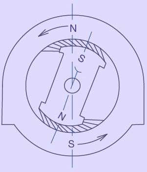
Figure 24: Elementary synchronous motor action - Attraction of the unlike poles keep the rotor locked to the rotating field produced in the stator
Behaviour of a loaded synchronous motor Likewise when a synchronous machine operates as a motor with a mechanical load on its shaft, it draws an alternating current which interacts with the main flux to produce a driving torque. The torque remains unidirectional only if the rotor moves one pole-pitch per half-cycle; i.e. it can run only at the synchronous speed. In a balanced three-phase machine, the armature reaction due to the fundamental component of the current is a steady mmf revolving synchronously with the rotor - its constant cross-component producing a constant torque by interaction with the main flux, while its direct-component affects the amount of the main flux. A very simple way of regarding a synchronous motor is illustrated in Fig. 24. The stator, like that of the induction motor produces a magnetic field rotating at synchronous speed. The poles on the rotor (salient-pole is shown in Fig. 24 only for clarity), excited by direct current in their field windings, undergo magnetic attraction by the stator poles, and are dragged round to align themselves and locked up with with the stator poles (of opposite polarity- obviously). On no load the axes of the stator and rotor poles are practically coincident. When a retarding torque is applied to the shaft, the rotor tends to fall behind. In doing so the attraction of the stator on the rotor becomes tangential to an extent sufficient to develop a counter torque - however the rotor continues to rotate only at synchronous speed.
The angular shift between the stator and rotor magnetic axes represents the torque (or load) angle (as shown later, in the phasor diagram). This angle naturally increases with the mechanical load on the shaft. The maximum possible load is that which retards the rotor so that the tangential attraction is a maximum. (It will be shown later that the maximum possible value for the torque angle is 90 electrical degrees - corresponding to a retardation of the rotor pole by one half of a pole pitch). If the load be increased above this amount, the rotor poles come under the influence of a like pole and the attraction between the stator and rotor poles ceases and the rotor comes to a stop. At this point we say that the synchronous motor pulled out of step. This situation arises much above the rated loads in any practical machine.
It is to be noted that the magnetic field shown in Fig. 24 is only diagrammatic and for better understanding of the action of the synchronous machine - the flux lines may be considered as elastic bands which will be stretched by application of the mechanical load on the shaft. Actually the flux lines will enter or leave the stator and rotor surfaces nearly normally, on account of the high permeability of these members. In a salient-pole machine the torque is developed chiefly on the sides of the poles and on the sides of the teeth in a non-salient-pole machine.
Concept of Synchronous Reactance
The operation of the synchronous machine can be reduced to comparatively simple expression by the convenient concept of synchronous reactance. The resultant linkage of flux with any phase of the armature of a synchronous machine is due, as has been seen, to the combined action of the field and armature currents. For a simple treatment it is convenient to separate the resultant flux into components: (a) the field flux due to the field current alone; and (b) the armature flux due to the armature current alone. This separation does not affect qualitative matters, but its quantitative validity rests on the assumption that the magnetic circuit has a constant permeability. In brief the simplifying assumptions are: 1. The permeability of all parts of the magnetic circuit of the synchronous machine is constant - in other words the field and armature fluxes can be treated separately as proportional to their respective currents so that their effects can be superposed. 2. The air gap is uniform, so that the armature flux is not affected by its position relative to the poles - in other words we assume the rotor to be cylindrical 3. The distribution of the field flux in the air gap is sinusoidal. 4. The armature winding is uniformly distributed and carries balanced sinusoidal currents.
In other words, the harmonics are neglected so that the armature flux is directly proportional to the fundamental component of the armature reaction mmf implying that the armature reaction mmf is distributed sinusoidally and rotates at synchronous speed with constant magnitude.
Assumption (1) is roughly fulfilled when the machine works at low saturation; (2) and (3) are obviously inaccurate with salient-pole machines and assumption (4) is commonly made and introduces negligible error in most cases. The behaviour of an “ideal” synchronous machine can be indicated qualitatively when the above assumptions (1) to (4) are made.
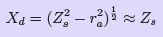
The phasor diagrams Fig. 25 for the several conditions contain the phasors of two emfs viz. Eo and E . The latter is the e.m.f actually existing, while the former is that which would be induced under no-load conditions, i.e. with no armature current (or armature reaction).
Thus Eo is the e.m.f. corresponding to the flux produced by the field winding only, while E is that actually produced by the resultant flux due to the combined effect of stator and rotor ampere-turns. The actual e.m.f. E can be considered as Eo plus a fictitious e.m.f. proportional to the armature current.
Fig. 25 is drawn in this manner with Er such that the following phasor relationship is satisfied:
E = Eo + Er (19)
It can be seen from Fig. 25, that Er , is always in phase-quadrature with armature current and proportional to it (as per the four assumptions (1) to (4) above). The emf Er is thus similar to an emf induced in an inductive reactance, so that the effect of armature reaction is exactly the same as if the armature windings had a reactance xa = Er /Ia . This fictitious reactance xa can added to the armature leakage reactance xl and the combined reactance ( xa + xl ) is known as the synchronous reactance xs. The armature winding apart from these reactance effects, presents a resistive behaviour also. Synchronous impedance is a tern used to denote the net impedance presented by each phase of the alternator winding, consisting of both resistive and reactive components. The behavior of a synchronous machine can be easily predicted from the equivalent circuit developed using this synchronous reactance xs, as explained in the following section.
Approximation of the Saturated Synchronous Reactance
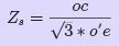
Economical size requires the magnetic circuit to be somewhat saturated under normal operating conditions. However, the machine is unsaturated in the short-circuit test, and the synchronous reactance based on short-circuits and open-circuit test data is only an approximation at best. Nevertheless, there are many studies in which a value based on rated open-circuit voltage and the short circuit current suffices. Hence, in Fig. 29, if oc is rated voltage, ob is the required no-load field current, which also produces the armature current o′e on short circuit. The synchronous impedance assuming the armature winding is star-connected is, accordingly,
 20)
20)
Except in very small machines, the synchronous reactance is much greater than the resistance (ra ) of the armature and the saturated value as well as the unsaturated value of the synchronous reactance and therefore is considered equal to the magnitude of the synchronous impedance
 (21)
(21)
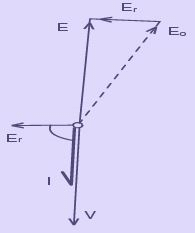
(b)Motor unity power factor
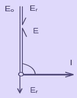
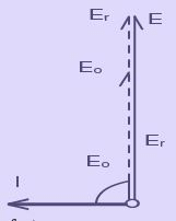
(c) Generator (d)Generator zero power factor
Figure 25: Phasor diagrams for different operating conditions
The line of in Fig. 29 is more nearly representative of the saturated machine than is the air-gap line. On the basis of this line, an estimate of the field current can be obtained for a given terminal voltage, load current, and power factor. This is done by calculating Eaf and making use of the saturated synchronous reactance as follows.
Eaf = V + ZsI (22)
The field current is that required to produce Eaf on the line of.
Open-circuit and Short-circuit Tests
The effect of saturation on the performance of synchronous machines is taken into account by means of the magnetization curve and other data obtained by tests on an existing machine. Only some basic test methods are considered. The unsaturated synchronous impedance and approximate value of the saturated synchronous impedance can be obtained form the open-circuit and short-circuit tests.
In the case of a constant voltage source having constant impedance, the impedance can be found by dividing the open-circuit terminal voltage by the short circuit current.
However, when the impedance is a function of the open-circuit voltage, as it is when the machine is saturated, the open-circuit characteristic or magnetization curve in addition to the short-circuit characteristic is required.
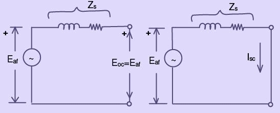
Figure 26: Synchronous generator(a) Open circuit (b) Short circuit
The unsaturated synchronous reactance is constant because the reluctance of the unsaturated iron is negligible. The equivalent circuit of one phase of a polyphase synchronous machine is shown in Fig. 26 for the open-circuit condition and for the short circuit condition. Now Eaf is the same in both cases when the impedance Zs. Where Eaf is the open-circuit volts per phase and Isc is the short-circuit current per phase.
Open-circuit Characteristic
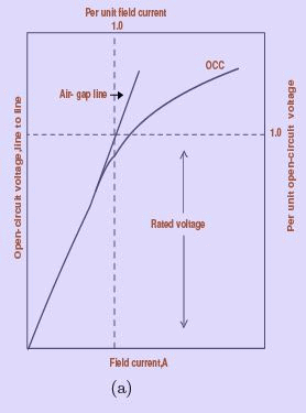
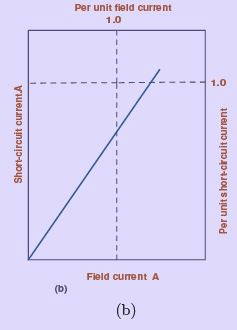
Figure 27: (a) Open circuit characteristic and (b) Short-circuit characteristic
To obtain the open-circuit characteristic the machine is driven at its rated speed without load. Readings of line-to-line voltage are taken for various values of field current. The voltage except in very low-voltage machines is stepped down by means of instrument potential transformers. Fig. 27 shows the open-circuit characteristic or no-load saturation curve. Two sets of scales are shown; one, line to-line volts versus field current in amperes and the other per-unit open-circuit voltage versus per-unit field current. If it were not for the magnetic saturation of the iron, the open-circuit characteristic would be linear as represented by the air-gap line in Fig. 27. It is important to note that 1.0 per unit field current corresponds to the value of the field current that would produce rated voltage if there were no saturation. On the basis of this convention, the per-unit representation is such as to make the air-gap lines of all synchronous machines identical.
Short circuit Test
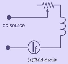
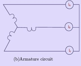
Figure 28: Connections for short-circuit test
The three terminals of the armature are short -circuited each through a currentmeasuring circuit, which except for small machines is an instrument current transformer with an ammeter in its secondary. A diagram of connections in which the current transformers are omitted is shown in Fig. 28.
The machine is driven at approximately synchronous (rated) speed and measurements of armature short-circuit current are made for various values of field current, usually up to and somewhat above rated armature current. The short-circuit characteristic (i.e. armature short circuit current versus field current) is shown in Fig. 27. In conventional synchronous machines the short-circuit characteristic is practically linear because the iron is unsaturated up to rated armature current and somewhat beyond, because the magnetic axes of the armature and the field practically coincide (if the armature had zero resistance the magnetic axes would be in exact alignment), and the field and armature mmfs oppose each other.
Unsaturated Synchronous Impedance
The open circuit and short-circuit characteristics are represented on the same graph in Fig. 29. The field current oa produces a line-to line voltage oc on the air- gap line, which

Figure 29: Open-circuit and short circuit characteristic
would be the open-circuit voltage if there were no saturation. The same value of field current produces the armature current o’d and the unsaturated synchronous reactance is given by:
 phase, for a star connected armature (23)
When the open-circuit characteristic, air-gap line, and the short-circuit characteristic are plotted in per-unit, then the per unit value of unsaturated synchronous reactance equals the per-unit voltage on the air-gap line which results from the same value of field current as that which produces rated short-circuit (one-per unit) armature current. In Fig. 29 this would be the per-unit value on the air gap line corresponding to the field current og.
|
23 videos|98 docs|42 tests
|
FAQs on Synchronous Machine Armature Windings - 2 - Electrical Engineering SSC JE (Technical) - Electrical Engineering (EE)
| 1. What are armature windings in a synchronous machine? |  |
| 2. How are armature windings connected in a synchronous machine? | |
| 3. What is the purpose of armature windings in a synchronous machine? | |
| 4. How are armature windings designed in a synchronous machine? | |
| 5. What are some common types of armature windings used in synchronous machines? | |


Synchronous Machine Armature Windings - 2 | Electrical Engineering SSC JE (Technical) - Electrical Engineering (EE)
,past year papers
,Synchronous Machine Armature Windings - 2 | Electrical Engineering SSC JE (Technical) - Electrical Engineering (EE)
,Extra Questions
,Exam
,Free
,Important questions
,Semester Notes
,mock tests for examination
,ppt
,Objective type Questions
,Summary
,Sample Paper
,Viva Questions
,study material
,MCQs
,practice quizzes
,Previous Year Questions with Solutions
,shortcuts and tricks
,video lectures
,Synchronous Machine Armature Windings - 2 | Electrical Engineering SSC JE (Technical) - Electrical Engineering (EE)
;


Synchronous Machine Armature Windings - 2 Free PDF Download
Importance of Synchronous Machine Armature Windings - 2
Synchronous Machine Armature Windings - 2 Notes
Synchronous Machine Armature Windings - 2 Electrical Engineering (EE) Questions
Study Synchronous Machine Armature Windings - 2 on the App
|
© EduRev
|
Education Revolution
|


|


