Synchronous Generator Operation - 2 | Electrical Engineering SSC JE (Technical) - Electrical Engineering (EE) PDF Download

Salient Pole Rotor Machine
As discussed earlier in Sec. 3.1 the behaviour of a synchronous machine on load can be determined by the use of synchronous reactance xs which is nothing but the sum of xa and xl , where xa is a fictitious reactance representing the effect of armature reaction while xl is the leakage reactance. It was also mentioned that this method of representing the effect of armature reaction by a fictitious reactance xa was applicable more aptly only for a cylindrical rotor (non-salient pole) machine. This was so as the procedure followed therein was valid only when both the armature and main field m.m.f.’s act upon the same magnetic circuit and saturation effects are absent.
Theory of Salient-pole machines (Blondel’s Two-reaction Theory)
It was shown in Sec. ?? that the effect of armature reaction in the case of a salient pole synchronous machine can be taken as two components - one acting along the direct axis (coinciding with the main field pole axis) and the other acting along the quadrature axis (inter-polar region or magnetic neutral axis) - and as such the mmf components of armature-reaction in a salient-pole machine cannot be considered as acting on the same magnetic circuit. Hence the effect of the armature reaction cannot be taken into account by considering only the synchronous reactance, in the case of a salient pole synchronous machine.
In fact, the direct-axis component Fad acts over a magnetic circuit identical with that of the main field system and produces a comparable effect while the quadrature-axis component Faq acts along the interpolar space, resulting in an altogether smaller effect and, in addition, a flux distribution totally different from that of Fad or the main field m.m.f.
This explains why the application of cylindrical-rotor theory to salient-pole machines for predicting the performance gives results not conforming to the performance obtained from an actual test.
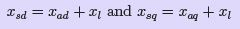
Blondel’s two-reaction theory considers the effects of the quadrature and direct-axis components of the armature reaction separately. Neglecting saturation, their different effects are considered by assigning to each an appropriate value of armature-reaction “reactance,” respectively xad and xaq . The effects of armature resistance and true leakage reactance ( xl ) may be treated separately, or may be added to the armature reaction coefficients on the assumption that they are the same, for either the direct-axis or quadrature-axis components of the armature current (which is almost true). Thus the combined reactance values can be expressed as :
 (36)
(36)
for the direct- and cross-reaction axes respectively. These values can be determined experimentally as described in Sec. 3.2.3
In a salient-pole machine, xaq , the cross- or quadrature-axis reactance is smaller than xad , the direct-axis reactance, since the flux produced by a given current component in that axis is smaller as the reluctance of the magnetic path consists mostly of the interpolar spaces.
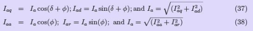
It is essential to clearly note the difference between the quadrature- and direct-axis components Iaq , and Iad of the armature current Ia, and the reactive and active components Iaa and Iar . Although both pairs are represented by phasors in phase quadrature, the former are related to the induced emf Et while the latter are referred to the terminal voltage V .
These phasors are clearly indicated with reference to the phasor diagram of a (salient pole) synchronous generator supplying a lagging power factor (pf ) load, shown in Fig. ??(a). We
where σ = torque or power angle and φ = the p.f. angle of the load.
The phasor diagram Fig. 34 shows the two reactance voltage components Iaq ∗ xsq and Iad ∗ xsd which are in quadrature with their respective components of the armature current.
The resistance drop Ia ∗ Ra is added in phase with Ia although we could take it as Iaq ∗ Ra and Iad ∗ Ra separately, which is unnecessary as
Ia = Iad + j Iaq
Actually it is not possible to straight-away draw this phasor diagram as the power angle σ is unknown until the two reactance voltage components Iaq ∗ xsq and Iad ∗ xsd are known. However this difficulty can be easily overcome by following the simple geometrical construction shown in Fig. 34(d), assuming that the values for terminal voltage V , the load power factor (pf ) angle φ and the two synchronous reactances xsd and xsq are known to us.
The resistance drop Ia ∗ Ra (length AB) is added to the tip of the voltage phasor (OA) in phase with the current phasor (i.e. in a direction parallel to OQ ). Then we draw
line BC ( of length equal to Ia ∗ xsq ) and extend it to D such that BD will be (of length equal to Ia ∗ xsd ) at the extremity B of Ia ∗ Ra and at right-angles to Ia . Draw OC and extend it (to F ). From D draw the perpendicular DF on OC extended. Then OF represents the induced voltage Et. The proof for this can be given as follows:. If DF is extended to G such that this line is perpendicular to BG drawn parallel to OF, we have :

Power relations in a Salient Pole Synchronous Machine:
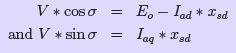
Neglecting the armature winding resistance, the power output of the generator is given by:
P = V ∗ Ia ∗ cos φ (41)
This can be expressed in terms of σ, by noting from Fig. 34 that :
 (42)
(42)
Substituting these in the expression for power, we have.

It is clear from the above expression that the power is a little more than that for a cylindrical rotor synchronous machine, as the first term alone represents the power for a cylindrical rotor synchronous machine. A term in (sin 2σ) is added into the power - angle characteristic of a non-salient pole synchronous machine. This also shows that it is possible to generate an emf even if the excitation E0 is zero. However this magnitude is quite less compared with that obtained with a finite E0. Likewise we can show that the machine develops a torque - called the reluctance torque - as this torque is developed due to the variation of the reluctance in the magnetic circuit even if the excitation E0 is zero.
Experimental Determination of xd and xq
The unsaturated values of xd and xq of a 3-Phase synchronous machine can be easily determined experimentally by conducting the following test known as slip test. The rotor of
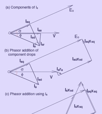
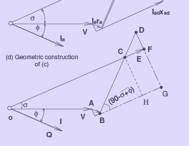
Figure 34: Phasor diagram of a generator-Two reaction theory
the synchronous machine is driven by means of a prime mover (usually a DC motor in the laboratory) at a speed close to the synchronous speed in the proper direction but not equal to it. The armature is supplied with a low voltage 3-Phase balanced supply through a variac, while the field circuit is kept open. The armature current varies between two limits since it moves through, since the synchronously rotating armature mmf acts through the varying magnetic reluctance paths as it goes from inter-polar axis to pole axis region. The values of xsd and xsq are determined based on the applied voltage and the armature current values.
The ratio of applied voltage to the minimum value of the armature current gives the direct axis synchronous reactance xsd which is usually the same as the synchronous reactance xs that we usually determine from normal no-load and short-circuit tests as explained in Sec. ?? The ratio of applied voltage to the maximum value of the armature current gives the the quadrature-axis reactance xsq . For more accurate determination of these values the oscillogram of the armature current and voltage can be recorded.
Losses and Efficiency
To calculate the efficiency of a synchronous generator, a procedure is to be followed for establishing the total losses when operating under load. For generators these losses are,
1. Rotational losses such as friction and windage.
2. Eddy current and hysteresis losses in the magnetic circuit
3. Copper losses in the armature winding and in the field coils
4. Load loss due to armature leakage flux causing eddy current and hysteresis losses in the armature-surrounding iron.
With regard to the losses, the following comments may be made,
1. The rotational losses, which include friction and windage losses, are constant, since the speed of a synchronous generator is constant. It may be determined from a no-load test.
2. The core loss includes eddy current and hysteresis losses as a result of normal flux density changes. It can be determined by measuring the power input to an auxiliary motor used to drive the generator at no load, with and without the field excited. The difference in power measured constitutes this loss.
3. The armature and field copper losses are obtained as Ia2Ra and Vf If Since per phase quantities are dealt with, the armature copper loss for the generator must be multiplied by the number of phases. The field winding loss is as a result of the excitation current flowing through the resistance of the field winding.
4. Load loss or stray losses result from eddy currents in the armature conductors and increased core losses due to distorted magnetic fields. Although it is possible to separate this loss by tests, in calculating the efficiency, it may be accounted for by taking the effective armature resistance rather than the dc resistance.
After all the foregoing losses have been determined, the efficiency η is calculated as,
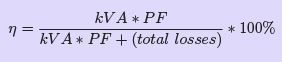 (44)
(44)
where η = efficiency,
kvA = load on the generator (output) PF = power factor of the load
The quantity (kVA*PF) is, of course, the real power delivered to the load (in kW) by the synchronous generator. Thus, it could in general be stated as
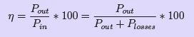 (45)
(45)
The input power Pin = Pout + Plosses is the power required from the prime mover to drive the loaded generator.
|
23 videos|94 docs|42 tests
|
Additional FAQs on Synchronous Generator Operation - 2 - Electrical Engineering SSC JE (Technical) - Electrical Engineering (EE)
| 1. What is a synchronous generator? |  |
| 2. How does a synchronous generator operate? | |
| 3. What is the significance of synchronizing a generator with the electrical grid? | |
| 4. What are the advantages of using a synchronous generator? | |
| 5. How is the reactive power controlled in a synchronous generator? | |


Summary
,Synchronous Generator Operation - 2 | Electrical Engineering SSC JE (Technical) - Electrical Engineering (EE)
,study material
,shortcuts and tricks
,past year papers
,Semester Notes
,Synchronous Generator Operation - 2 | Electrical Engineering SSC JE (Technical) - Electrical Engineering (EE)
,video lectures
,Exam
,Important questions
,mock tests for examination
,ppt
,Objective type Questions
,MCQs
,Extra Questions
,Synchronous Generator Operation - 2 | Electrical Engineering SSC JE (Technical) - Electrical Engineering (EE)
,practice quizzes
,Viva Questions
,Sample Paper
,Free
,Previous Year Questions with Solutions
;


Synchronous Generator Operation - 2 Free PDF Download
Importance of Synchronous Generator Operation - 2
Synchronous Generator Operation - 2 Notes
Synchronous Generator Operation - 2 Electrical Engineering (EE) Questions
Study Synchronous Generator Operation - 2 on the App
|
© EduRev
|
Education Revolution
|


|


